The throttle valve is one of the key components that is responsible for the operation of a car engine. It is part of the intake system, and its proper operation determines the amount of air that enters the combustion chamber, where it detonates after mixing with gasoline.
In order for the detonation process to be as efficient as possible, the vehicle's electronic control unit must control the timing of the throttle valve opening, thereby allowing in as much air as is required to create the ideal mixture at a particular moment in time. The corresponding sensor is responsible for information about what position the throttle valve is in. If it fails, the driver will face troubles that can lead to damage to engine parts.
DPDZ area of responsibility
In this article we will look at the features of this part and provide detailed instructions for its repair, adjustment and replacement. But before moving directly to the practical part, you should pay a little attention to theory and consider what the throttle valve and its sensor are, what functions they perform and where they are located. So, the damper itself is a structural component of the engine intake system. Its functions include adjusting the amount of incoming air, i.e. it is responsible for the quality of the fuel-air mixture.
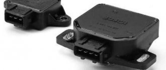
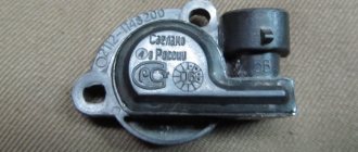
The throttle position sensor provides information to the manifold about the state of the bypass valve. This is obvious from its name. The sensor can be film or non-contact (magnetic). Its design is similar to an air valve, and when it is open, the pressure in the system is equal to atmospheric pressure. But as soon as the element moves to the closed position, the value of the above characteristic immediately decreases to a vacuum state.
Throttle position sensor
The throttle sensor consists of constant and variable resistors, the resistance of which reaches 8 ohms. The voltage at its output, depending on the position of the damper itself, constantly changes. The entire process is monitored by a controller, and the amount of fuel is adjusted depending on the data received. If the TPS does not work correctly and produces distorted data, then not enough fuel will enter the system or there will be an excess of it, which will lead to disruption of the engine and even sometimes its failure. In addition, the correct operation of the gearbox and ignition timing depend on this device. We will not calculate how much it will cost to repair these mechanisms.
To diagnose any unit or part, you need to know its location. The throttle position sensor is located in the engine compartment. You can get to it after you find the throttle pipe, on which the TPS is fixed.
This is interesting: How to set the ignition of YaMZ 238 - fuel injection pump adjustment
What does the throttle position sensor read?
When the driver presses the gas pedal, a special damper that regulates the volume of air entering the cylinders opens. Accordingly, the amount of gasoline in the mixture should increase. On a carburetor engine, more fuel simply flows through the jets under the influence of air flow. But on an “injection” car, the injection is strictly dosed. The supply of gasoline is increased by adjusting the opening time of the injectors. And the ECU learns about changes in the situation from two main devices:
- Throttle position sensor.
- Mass air flow sensor.
It is the TPS that tells the computer how much the damper has opened.
How the TPS works and works
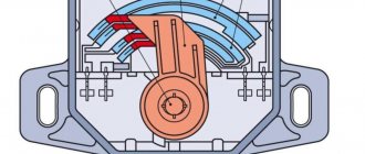
This sensor is based on an ordinary rheostat. The process occurs in this way: when the driver presses the gas pedal, the cable pulls the throttle valve drive. The shaft on which it is mounted rotates. The sensor core also rotates accordingly, moving the closing contact analogous to the rheostat winding. It receives voltage from the controller. The output signal is returned to the ECU. By changing the resistance in the circuit, the computer determines by what percentage the damper is open. And accordingly changes the opening time of the injectors. That is, in fact, the TPS conditionally consists of the following parts:
- Frame.
- Core with contact.
- Rheostat (analog).
Symptoms of a problem
So, what happens if this sensor fails. Well, firstly, since this device belongs to the ECM, the “Check Anger” warning light on the “Priora” dashboard will light up. Secondly, there will be tangible changes in the operation of the machine. “Dips” will begin when you gain speed, and small jerks when moving. And spontaneous “swimming” of speed at idle.
In general, with this breakdown, the decrease in driving comfort is very noticeable.
Why might we need to repair the sensor?
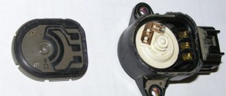
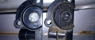
Nothing eternal has yet been invented, and this element is also breaking. Let's consider what reasons can provoke its failure and how this can be noticed. Throttle position sensor malfunctions are mainly caused by normal wear and tear. Thus, the sprayed base layer along which the slide moves wears out. As a result, the device gives incorrect readings. Another reason for incorrect operation may be the failure of the movable core. And if one of the tips is damaged, then a number of scratches will appear on the substrate, which will lead to breakage of the remaining elements. This will cause deterioration of contact between the resistive layer and the slider, and in some cases, its absence.
Worn throttle position sensor
You can understand that it’s time to contact a service center or carry out independent diagnostics and, if necessary, repairs, based on the following signs. First of all, listen to your car while idling; if the speed “floats”, then do not hesitate to check the device. Another warning sign should be the engine stopping when the pedal is suddenly released. And when accelerating, it may seem that fuel is not getting into the system, the car twitches and jerks appear.
Sometimes the revolutions seem to hang in one range (1.5–3 thousand) and do not change their position even when switching to neutral gear. In addition, the dynamics deteriorate. In general, the slightest disturbance in engine operation should alert you. By the way, pay attention to the dashboard, the “Check engine” warning light should light up on it. If this happens, then your car automatically goes into emergency mode, and after doing computer diagnostics, you will see that the reason lies precisely in the sensor.
What is a throttle position sensor
Each of the sensors in the engine control system is a simple detector that is designed to perform one specific task. In our case, the position sensor determines the angle of movement of the throttle valve, which in turn repeats the movement of the accelerator pedal. For all its apparent simplicity, the sensor is not so simple, since it may have a simple contact design, or it may have a more complex and precise operating mechanism. More specifically, the sensors can be
- Contactless.
- Film resistive.
Resistive sensors are much simpler in design, cheaper, but also fail more often. They are almost an ordinary variable resistor with three contacts.
Methods for diagnosing TPD
The most common test of the sensor is to measure resistance or voltage at various throttle positions (closed, half-open, and fully open). We will perform testing using the voltage measurement function.
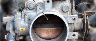
- Open the hood and remove the air filter assembly where it connects to the throttle body.
- Inspect the throttle plate and the throttle body walls around it.
* If you see carbon deposits on the walls or under the choke plate, clean this assembly using carburetor cleaner (carb cleaner) and a clean rag. The surface must be completely clean. Carbon deposits and dirt can prevent the throttle valve from closing and moving freely.
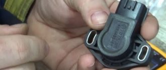
- Locate the TPS mounted on the side of the throttle body. The sensor is made in the form of a small plastic block with a three-wire connector.
Is your TPS connected to ground?
- Carefully disconnect the electrical connector from the throttle position sensor.
- Check the connector and terminal for dirt or damage.
- Set the multimeter to a suitable mode, for example, 20V on the DC voltage (DCV) scale.
- Turn the ignition key to the ON position, but do not start the engine.
- Connect the red multimeter probe to the positive terminal of the battery, indicated by the “+” symbol.
- Touch the black probe of the multimeter to each of the three electrical contacts of the wiring connector that connects to the TPS.
* One of the contacts, when touched, a voltage of about 12 volts appears on the multimeter screen, is the ground contact. Pay attention to the color of this wire.
*If none of the terminals indicate 12 volts, this is a sign of a defect in the wiring that goes to the throttle position sensor. The sensor is not grounded, so it cannot work properly. In such a situation, you need to solve the wiring problem.
- Turn off the ignition.
Is the TPS connected to the reference voltage source?
- Now connect the black probe of the multimeter to the ground pin on the TPS connector you just identified.
- Turn the ignition key to the ON position, but do not start the engine.
- Connect the red multimeter probe to each of the other two pins of the connector.
- The voltage at one of the contacts should be about 5 volts. This contact transmits the reference voltage to the TPS. Pay attention to the color of the wire connected to this pin. The third wire is the signal wire.
*If there is no 5 volts on either of the two pins of the connector, there is a problem in the wiring that needs to be corrected. Check the electrical circuit for loose connections or damaged wires.
- Turn off the ignition.
- Insert the electrical connector into the TPS.
Is the throttle position sensor giving the correct signal?
- To perform this test, you need to use a pair of pins or paper clips.
- Connect the red probe of the tester to the signal wire of the sensor, and the black one to the ground wire.
- Turn on the ignition, but do not start the engine.
- Make sure the throttle valve is completely closed.
- Your multimeter should read between 0.2-1.5 volts or so, depending on your specific vehicle. If you see zero on the screen, make sure you have selected the correct device mode - usually 10 or 20 volts is optimal. If the screen still shows zero, continue checking.
- Open the throttle gradually until it is fully open (or have a helper gradually push the gas pedal all the way down).
*When the throttle is wide open, the multimeter should read about 5 volts.
* Make sure the voltage gradually increases when you open the throttle slowly.
*If you notice that there are voltage spikes at certain damper positions or that it is stuck at the same level, your TPS is not working correctly and will need to be replaced.
* If the throttle position sensor does not reach 5 volts or so (3.5 volts on some vehicles) when the throttle is wide open, it needs to be replaced.
- Turn off the ignition and remove the pins (clips).
If your vehicle has an adjustable throttle position sensor (found on older models) and the readings are not correct, try adjusting it first. The sensor is adjustable if you can loosen its mounting bolts and turn the element to the left or right.
Adjusting the throttle position sensor
This method is suitable for setting up an external sensor. The following tips will give you a general idea of the TPS adjustment procedure.
- Loosen the sensor mounting bolts until you can rotate it by lightly tapping it with the handle of a screwdriver.
- Pull back the sensor to check the voltage using a multimeter.
- Turn the ignition key to the ON position, but do not start the engine.
- Hold the throttle valve in the closed position (or as specified in your vehicle's repair or service manual).
- Make sure the voltage is as specified in the manual. If not, turn the sensor left or right until you get the specified voltage.
- Hold the TPS in this position and tighten the mounting screws.
If the sensor cannot be adjusted and does not reach the required voltage, replace it.
Knowing how to test your throttle sensor can save you time and help you avoid unnecessary component replacements. With a simple test you can get your car back on the road faster. This check can be easily completed in just a few minutes.
The principle of operation of TPS with a potentiometer
The TPS sends information to the controller about idle speed, deceleration, acceleration rate and wide open throttle (WOT) status.
The TPS is a three-wire potentiometer. The first wire supplies a voltage of + 5 V to the resistive layer of the sensor, the second wire is ground. The third wire is connected to the potentiometer slider, which changes the resistance and therefore the voltage of the signal returned to the ECU.
Based on the received voltage, the control unit can calculate idle speed (below 0.7 V), full load (about 4.5 V) and throttle opening speed.
At full load, the ECU ensures that the fuel mixture is enriched. In deceleration mode (closed throttle and engine speed above certain rpm), the controller disables fuel injection. Fuel delivery is resumed when the engine speed reaches its idle speed or when the throttle valve opens. On some vehicles these values can be adjusted.
Adjustment in your garage
Even a novice car enthusiast can adjust the throttle position sensors; the main thing is to strictly follow the instructions given below. Moreover, this operation does not depend on the operating principle of the TPS – non-contact or not. So, first we carry out the preparatory work. We disconnect the corrugated tube through which air passes and thoroughly rinse it with alcohol, gasoline or another strong solvent. But one liquid is not always enough; to achieve a better effect, you should also wipe the tube with a soft cloth. We carry out the same operation with the damper itself and with the intake manifold. In addition, do not forget to carry out visual inspection, especially for the damper.
Operating principle of TPS
So, no mechanical damage was detected? Then we proceed directly to adjusting the throttle position sensor. First, take the key and loosen the screws. Then we raise the damper and sharply lower it all the way, keep in mind that you should hear a blow, otherwise repeat the operation again. Loosen the screws until the part stops “biting.” And only then can the position of the fasteners be secured with nuts. Next, unscrew the bolted connections of the TPS and rotate the device body. Next, we set the throttle position sensor so that the voltage changes only when the valve opens. The setup is complete, all that remains is to return everything to its place, tighten the bolts and enjoy driving your favorite car.
Checking in lamps
The throttle must be checked if one of the above-described phenomena is observed when the fluorescent lamp is operating, as well as if a characteristic smell of burning insulation is noticed, sounds that are not typical for the operation of the device are observed, and also if the lamp does not turn on.
Before checking the lamp choke, the lamp itself and the starter are checked.
A malfunction of the inductor may consist of a break or burnout of the coil wire or an interturn short circuit caused by breakdown or burning of the insulation.
Both malfunctions can occur either due to a long period of use of the device, or as a result of any mechanical impact. It is possible for the coil wire to burn out as a result of supplying it with a current greater than the maximum for which the inductor is designed.
In the event of a wire break or burnout, you can identify the fault with a conventional tester or multimeter. Due to the fact that the inductor passes direct current, closing the tester circuit through the coil, you can understand by the glow of the control lamp or its absence whether there is a break or not.
If, when measured with a multimeter, the resistance is infinite, the coil wire has broken.
Replacement and selection of sensor - non-contact or film?
If the element fails, then its complete replacement will most likely save the situation. One of the important points of this stage is the correct choice of a new device. Of course, if you do not want to carry out all the operations again in a short period of time, then you should give preference only to high-quality products, and even more so avoid cheap Chinese counterfeits. In addition, do not stop your choice on film-resistive models. They are short-lived, and such savings can cost you a pretty penny. But contactless throttle position sensors are more reliable. They only cost a few dollars.
Non-contact TPS
The film model has resistive tracks, while the non-contact model works on the principle of the magnetic effect. Its components are a stator, a rotor and a magnet. On the first, the magnetic field has a huge impact. The material of the second one is chosen such that the magnet does not have any influence on it. The distance between the TPS elements does not change and is selected at the assembly stage. Needless to say, the contactless sensor cannot be repaired.
The replacement itself will take you much less time than choosing a device. But despite the fact that the process is quite simple, let’s consider it in detail. We prepare a Phillips screwdriver, an O-ring for the throttle pipe and, of course, the part itself. The replacement begins by turning off the ignition if the car has been started. Open the hood and do not forget to disconnect the battery. To do this, remove the negative terminal.
Installation of TPS
Now we find the sensor on the throttle pipe and remove the block with wires from it; most likely you will have to press out the special plastic latch. Then unscrew the mounting bolts and dismantle the device. There is a foam ring between the TPS and the pipe, and it definitely needs to be replaced. And only after this can the sensor itself be installed. Fix the device firmly with bolts, otherwise the vibration will not do it any good and will cause failure. Reconnect the block with all the wires. Sometimes people forget to disconnect the battery; in this case, it is necessary to de-energize it for at least five minutes after installing the new device and connecting the plug to it.
You can check whether the element is working correctly as follows. Open the damper and pull the throttle cables to turn the TPS drive sector. If the position of the sector does not change, then the sensor should be installed again. At the same time, we rotate it 90 degrees relative to the damper axis. And finally, check the voltage with a tester; if its values coincide with those indicated above, then the device is working.
This is interesting: How to check the oil level in an automatic transmission (automatic transmission)
Replacing a spare part
DPDZ ZMZ 406 is located on the side of the throttle pipe. When replacing, remove the contact connector of the ECU cable. Use a Phillips screwdriver to unscrew the mounting bolts and remove the device. The new sensor is installed in the reverse order.
You should only purchase a new sensor from trusted suppliers. It is risky to buy cheap devices, as this can result in unexpected troubles on the road when you have to barely trudge along the highway in search of the nearest service station.
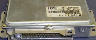
Mikas is a comprehensive car engine control system. Similar to the January system. The system includes: a set of sensors (input periphery), an electronic control unit (ECU), a set of actuators (output periphery) and a wiring harness with connectors (performs the functions of a simple interface)*. The system can use components of both domestic production and Bosch. There are 5 main modifications in total: 5.4, 7.1, 10.3, 11 and 12.3 versions.
Car engine diagnostics begins with reading error codes from the controller's RAM. Checking the wiring is quite simple if you have a Mikas pinout (pin assignment) of the controller connector and a multimeter. As a last resort, you can use a control llama, but this is not entirely convenient. Next comes the pinout of the connectors of this ECU of various modifications:
The control unit is installed on GAZ vehicles in the passenger compartment on the front panel on the passenger side. The unit is connected to the wiring harness using a 55-pin socket with a latch. When connecting the harness socket to the unit, you must be careful and do not apply much force so as not to “crumple” the pins of the control unit plug. After installing (replacing) the unit, it is recommended to perform a CO adjustment at idle speed.
Types and versions of MIKAS-5.4 blocks
- 201.3763—for GAZ-3129, GAZ-3110 cars and for GAZ minibuses with a ZMZ-4062.10 engine with a synchrodisc.
- 207.3763—for GAZ-3129, GAZ-3110 cars and for GAZ minibuses with a ZMZ-4062.10 engine with a synchronization flywheel.
- 209.3763—for GAZelle cars and GAZ minibuses with ZMZ-4063.10 and ZMZ-4061.10 engines with a synchrodisc.
- 2012.3763—for GAZelle cars and GAZ minibuses with ZMZ-4063.10 and ZMZ-4061.10 engines with a synchronization flywheel.
Illusory repair possibilities
It should be said right away that repairing throttle position sensors is extremely rare. Firstly, the part itself, even the most expensive one, costs only a few dollars, and it makes sense to spend the money. Secondly, in most cases it is simply impossible to make repairs, for example, to restore a worn-out base layer. However, in some models you can slightly shift the resistive tracks relative to the slider and thereby extend the life of the device.
Throttle Position Sensor Repair
So, there is a special screw on the sensors. With its help, the position of the tracks is fixed. If they are already worn out, then you should loosen this same screw, this will change the location of the slider a little, and you can be a little patient with replacing the device. But don't count on long-term respite. Naturally, we remember that the contactless sensor cannot be repaired. This completes the adjustment, repair and replacement of the throttle position sensor, now you can operate the car for several more years and not even think about such issues.
Home →
Maintenance and Repair →
Repair →
Mikas 10.3 ECU connector pinout
Designations of components and circuits in the diagram
A1—engine control controller (unit); A2—electric fuel pump module with level sensor; A3—instrument combination or panel; A4—immobilizer (automobile anti-theft system APS); A5—trip computer; A6—accelerator pedal module (E-gas); A7—throttle device with electric drive; B1—throttle position sensor; B2—mass air flow sensor; B3—coolant temperature sensor; B4—air temperature sensor; B5—knock sensor; B6—oxygen sensor No. 1; B7—oxygen sensor No. 2; B8—rough road sensor; B9—fuel temperature sensor; B10—sensor for the presence of water in the fuel coarse filter; B11—sensor for the presence of water in the fine fuel filter; B12—sensor for clogging of the fine fuel filter; BP1—inlet air absolute pressure sensor; BP2—emergency oil pressure alarm sensor; BP3—air conditioner refrigerant pressure indicator sensor; BP4—fuel pressure sensor (diesel); BR1—synchronization sensor (crankshaft position); BR2—phase sensor (camshaft position); BV1—vehicle speed sensor; E1…E4—glow plugs (diesel); F1.F4—spark spark plugs for cylinders 1.4; FU1.FU6—fuse; HL1—MIL lamp for engine diagnostics; HL2—IMMO lamp for immobilizer status (ALS unit); HL3—EOBD diagnostic indicator (lamp); HL4—indicator (lamp) of the presence of water in the fuel; HL5—indicator (lamp) of clogging of the fine fuel filter; GB1—rechargeable battery; KA1—main relay; KA2—electric fuel pump relay; KA3, KA4—relay for electric fans No. 1 and No. 2 for engine cooling; KA5—air conditioning compressor clutch relay; KA6—glow plug relay (diesel); KA7— main relay No. 2 (additional); KA8—cooling fan electric coupling relay; KA9—fuel heater relay in the filter; L1—immobilizer transceiver antenna; M1—electric fuel pump; M2, M3—electric fans EVO-1 and EVO-2; PF1—tachometer; PS1—coolant temperature indicator; TV1, TV2—two-terminal ignition coil; TV3—ignition module with two-terminal coils; TV4 ignition individual; TV8—four-terminal ignition coil; W1.W4—high-voltage ignition wires; SA1—ignition switch; SA2—mass switch; SA3—air conditioner switch; SA4—two-channel brake pedal switch; SA5—clutch pedal switch; XS1—diagnostic connector; XS2—nozzle connector; Y1.Y4—fuel injection nozzles (petrol or diesel); Y5—additional air (idle) regulator; Y6—adsorber purge valve; Y7—electric coupling of the air conditioning compressor; Y8—exhaust gas recirculation valve; Y9—electric coupling for turning on the cooling fan; *—the component can be installed as an additional package.
Electrical circuits
“15”—circuit from the ignition switch; “30”—battery power circuit; “Um”—power circuit from the main relay of the system; “Ue”—power circuit from the electric fuel pump relay; GNP—power “ground” of the controller output stages; GNI—“ground” for power ignition channels; GND—“ground” for logical and digital circuits of the controller; GNA—“ground” for signal (analog) circuits of the controller; The remaining circuits are named controller pins.
Description of contacts of ECU Mikas 10.3
Types of TPS
In total, there are 2 options for the sensor device, one with a mechanical drive and the other with an electric drive. Mechanical modification can be found on inexpensive versions of cars. TPS is a separate block, it consists of the following components:
- Frame.
- Idle speed regulator.
- Sensor.
- Damper.
The damper body is also connected to the vehicle's cooling system. Additional pipes are also installed in this part; they are necessary for the fuel vapor compression system, as well as for crankcase cooling.
Throttle valve
The idle speed regulator, with the throttle closed, always maintains the crankshaft rotation period at the same level. This is done when the engine warms up, or when starting other vehicle equipment. The IAC consists of a stepped electric motor and a valve; together these two elements are capable of fully adjusting the air supply at the intake.
In recent years, TPS with electric drive have become increasingly popular. The fact is that experts of this modification note that with such a sensor it is possible to achieve the greatest torque. This is achieved by using an electronic computer for control. If the car has just such a modification, then the torque will remain constantly high at different speed ranges. It is also noted that in this case, fuel consumption is significantly lower, and exhaust gases are considered less toxic.
How to check?
You can check the serviceability of the sensor using 3 devices:
- diagnostic scanner;
- motor tester;
- multimeter.
Checking with a diagnostic scanner
We connect the scanner to the car and find the parameters in the program. In the parameters we find the throttle sensor readings. The scanner can display data from the sensor, both in volts and as a percentage. If in volts, then we look at the values within 5 V.
IMPORTANT! The scanner will display values from 0.3 to 4.7. This is done so that the control unit understands that the sensor is working. If there is “0” volts, then an error will appear - “sensor break”. If “5” volts, the damper is completely open or there is a short circuit.
If in percentage, then we look at the percentage of the damper opening from 0 to 100%. If everything is in order, then on the scanner when the damper is opened we will see percentages: 0%, 2%, 3%, etc.
If we see the values: 0%, 20%, 0%, 15%, 3%, 4%, 20%, etc. - this indicates wear of the resistive layer.
Checking the throttle sensor using the Launch scanner as a percentage. On the left are digital values, on the left in graphical form.
Motortester
To check the throttle sensor with a motor tester, you need to connect to the signal wire of the sensor and to the negative wire. Then we begin to open the damper. What should we see? If everything is good, then we will see the following waveform:
Oscillogram of a working sensor
If the resistive track is worn out, then the oscillogram will look like this:
Oscillogram of a faulty sensor
Noise at the beginning of the resistive trace is the first sign of wear.
Multimeter
When checking the throttle sensor with a multimeter, check the voltage between the positive and negative wires. The engine must be running at the same time. The measurement values should be about 5 volts.
The next step is to measure the resistance between the sensor signal wire and the negative wire. In this case, the ignition is turned off completely, and the multimeter is set to measure resistance.
In the closed position of the throttle valve, the multimeter should display values from 0.8 to 1.2 kOhm, and in the open position from 2.3 to 2.7 kOhm.
In lamps
In luminaires designed for the use of fluorescent lamps, in addition to the lamps themselves, components such as a starter and a choke are used.
The starter, as the name suggests, starts the glow process in the lamp and does not participate further in the process. The choke functions as a current and voltage stabilizer during the entire period of the lamp's glow.
If the choke is faulty, the lamp does not light or does not burn steadily, its glow is not uniform along its entire length, and areas with a brighter glow may appear inside, moving from one electrode of the lamp to another. Sometimes you can notice the flickering effect of the light.
If the throttle is faulty, the lamp may not light up the first time, and the starter will turn on repeatedly until the lighting process finally starts. As a result, dark spots will appear on the lamp bulb where the spirals are installed. This is due to the fact that the coils operate for a longer time than is set for normal starting.
Common causes of malfunction
Having talked a little about the device, you can understand that the main and most common breakdown of the sensor is wear of the resistive layer. Over time, the coating of the layer wears off, and then problems with the sensor appear.
Moreover, wear most often occurs at the beginning of the resistive track, since frequent movement of contacts occurs there (the car begins to move).
Wear of the resistive layer of the sensor track
Dirt on the working surface of the sensor can also cause a malfunction.
Less often you can stumble upon breakdowns in the operation of the sensor itself. This is a failure of the mechanical part of the moving unit, and a malfunction of the electronic magnetic signal converter.
Sensor device
This is a potentiometric type sensor - a potential meter. Such sensors are used where it is necessary to measure the spatial position of a component (fuel level sensor, for example).
Everyone will remember how at school they showed a rheostat, in which, by moving the slider along the resistive layer of the rheostat, we changed the voltage up or down.
Using this principle, we can find out in what position a particular unit is located.
This principle was used on Soviet equipment when adjusting the volume. By increasing the voltage, we increased the volume and vice versa.
Additional check of TPS
Next, it is worth testing the breaking of contacts XX. According to the standard, on many cars they are located on the sensor connectors at the bottom. Connect one end of the multimeter to the contact, and with the other we will move the throttle valve. If the voltage changes when cranking the throttle, then everything is fine and the sensor is working correctly. If the readings do not change at all, then try swapping the contacts of the measuring device. A constant value indicates a malfunction of the TPS; most likely the variable resistor has failed. If you are a good specialist and understand radio engineering, you can replace the resistor yourself. This is far from being considered correct, so we advise you to replace the entire module.
Variable resistor
This resistor is considered an integral part of the module design. The resistance on the resistor changes with different positions of the damper, and in this way its exact position is determined. In order to understand whether it is working correctly, you need to connect the remaining wire to the multimeter. The ignition is turned on, and then the throttle moves slowly. The voltage should gradually increase, remember that there should be no sudden jumps. If you notice them, then most likely you have engine problems. To diagnose them, you will need engine diagnostics; this will be done for you at the nearest car service center.
What is TPS: location and types
The location of the sensor is determined by its functional purpose. Structurally, to take readings, the sensor must be mounted on the throttle body. As a rule, it stands on the side opposite to the throttle valve drive and has a rigid mechanical connection with its axis.
There are several types of VAZ TPS:
- film-resistive throttle sensor VAZ (structurally simple potentiometers, they “run” up to 50-60 thousand kilometers);
- non-contact TPS (magnetoresistive). They work on the principle based on the Hall effect, service life is from 100 thousand km or more;