What are the symptoms of a P0120 code?
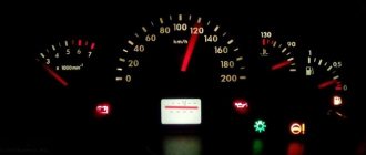
- When this error appears, the Check Engine light will light up on the vehicle's dashboard. The ECM will put the engine into limp mode and stop current flowing to the throttle actuator. In this case, the opening angle of the throttle valve will be no more than 6 degrees.
- Problems may arise with the control of fuel injection and ignition timing.
- Engine power may be reduced due to slow throttle response to changes in the accelerator pedal position.
- The engine may idle at higher speeds, but the vehicle will not accelerate as expected.
Note : Symptoms of this error may vary depending on the make and model of your vehicle.
Technical description and interpretation of error P0120
This diagnostic trouble code (DTC) is a generic powertrain code. The P0120 code is considered a common code because it applies to all makes and models of vehicles. Although the specific repair steps may vary slightly depending on the model.
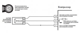
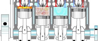
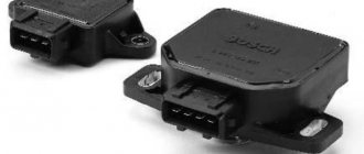
The throttle position sensor (TPS) responds to movement of the accelerator pedal. It is a type of potentiometer. Which converts the throttle position into a voltage output and supplies a voltage signal to the Engine Control Module (ECM). It also detects the opening and closing speed of the throttle valve and provides a voltage signal to the ECM.
Code P0120 means that the vehicle's computer has detected a TPS (throttle position sensor "A" voltage) that is outside the normal operating range. When the throttle is closed, the signal is about 0.45 volts, and the lower limit when open is 0.17 - 0.20 volts.
Simply put, the throttle position sensor is used to determine what position the throttle valve is in. If the signal value is very different from the reference value, then this code is set.
How does a mechanic diagnose a P0120 code?
When diagnosing this error, the mechanic will do the following:
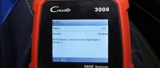
- Reads all stored data and error codes using an OBD-II scanner to find out when and under what circumstances the P0120 error occurred
- Clear error codes from the computer's memory and test drive the vehicle to see if P0120 appears again
- Visually inspect the electrical wires and connectors related to the throttle position sensor “A” for looseness or damage.
- Compare the readings of throttle position sensors “A” and “B” using a scanner and, if necessary, replace the faulty sensor
Error Conditions
The VTA1 circuit constantly transmits a signal to the ECU. Error p0120 will occur when the voltage in the circuit, with the throttle valve open, goes outside the standard range (0 to 5 volts) within a certain time interval.
The system is configured in such a way that only one error is recorded per trip.
The voltage and time interval readings for each car model, for example, Renault Logan and Mitsubishi Lancer 9, may differ, but not by much.
Let’s take, for example, a Toyota Corolla whose sensor produces a standard voltage of 0 to 5 Volts.
If the accelerator pedal is completely released, it is 0.5-1.1 V, if it is fully depressed - 3.3-4.9 V. We are talking about the VTA1 circuit.
If the voltage is below 0 or more than 5 volts for 2 or more seconds, the system will generate error p0120.
Very often, this error occurs when driving on mountain roads, when the car is overloaded, the gas pedal is pressed hard and the engine runs for a long time at high speeds.
Common mistakes when diagnosing code P0120
- Failure to visually inspect the throttle position sensor “A”, as well as the associated electrical wires and connector
- Neglecting to check for an error code using a scanner, clearing the code from the computer's memory, and rechecking the system before performing any repair work
- Hasty replacement of throttle position sensor “A”
- Neglecting to check the readings and performance characteristics of the throttle position sensors “A” and “B” before starting repair work and after its completion
Reasons for the error
Causes of error p0120:
- Broken wires going directly from the sensor to the ECU.
- Oxidation of contacts in connectors.
- Damage to the sensor itself. Short circuit, break in the electrical circuit of the device.
- Damage and deformation of the throttle body. Since the sensor is internal, this may affect its operation.
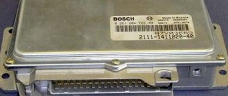
- ECU malfunction. A software or electronics failure can cause a false signal to be output to the instrument panel.
- Malfunction of the ECM engine control module.
- PCM malfunction. A combined control module consisting of an engine control unit (ECU) and a transmission control module (TCM).
- The valve is dirty or a foreign object has entered it.
- The battery is low.
There are other possible causes that are rare and can only be diagnosed by experienced specialists.
Additional comments for troubleshooting P0120
- Along with the P0120 code, there may also be other error codes related to the throttle position sensor that need to be investigated and resolved.
- The most common cause of P0120 is a faulty throttle position sensor that is not properly detecting the throttle angle.
- As a rule, when errors related to the throttle position sensor appear, emergency mode is activated, and the symptoms of such errors are almost the same.
Symptoms of malfunction
The main driver symptom of P0120 is the MIL (Malfunction Indicator Light) illumination. It is also called Check engine or simply “check light”.
They can also appear as:
- The “Check engine” warning light on the control panel will light up.
- Jerking/misfire at idle or under load.
- The engine stalls or has trouble starting.
- The engine cannot be accelerated and the throttle response is unresponsive.
- Poor speed gain.
- Loss of engine power due to slow throttle response.
Other symptoms may also be present.
Diagnostics and troubleshooting
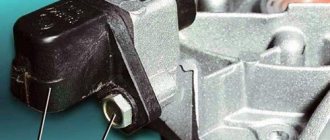
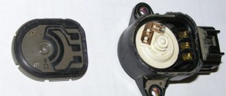
Despite the fact that the throttle position sensor is a simple device in its design, it is located directly in the throttle assembly, which complicates its diagnosis and makes it impossible to remove it as a separate element and replace it.
If your car has a throttle body (RC) with mechanical control via a cable, then you can remove and replace the sensor without replacing the entire remote control.
Inspection of the throttle valve assembly
Deposits and contaminants built up on and around the throttle valve, as well as foreign objects, can cause the P0120 code. All this can be revealed by visual inspection.
To remove contaminants, use a regular carburetor cleaner. This is not a difficult task even for an inexperienced driver.
It would also be a good idea to remove the intake air manifold and check the condition of the gaskets and O-rings. If necessary, replace them and seal them with sealant.
If after removing all contamination, error p0120 does not disappear, further diagnostics must be carried out. In rare cases, it all ends with a complete replacement of the throttle assembly.
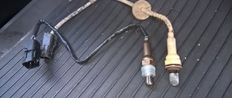
What is a throttle position sensor?
To understand the P0120 error, you first need to figure out what malfunction it indicates. The throttle position sensor (TPS or TP) is located directly on the throttle body and is responsible for fixing the throttle angle. This device is quite simple, which ensures its reliable operation for many years.
Please note: Many vehicles are capable of driving more than 300 thousand kilometers without problems with the throttle position sensor.
The throttle position sensor has two circuits, one of which is necessary to analyze information about the throttle position at a specific point in time, and the second is required to control the first. The voltage that is transmitted from the sensor to the electronic control unit changes depending on how much the damper is opened or closed. When the damper is closed, the voltage is 0 V (sometimes there is a different value - up to 0.5 V). When the damper is fully open, the voltage is 5 V. At different angles, the voltage increases and decreases within the specified limits.
Based on the information received from the throttle position sensor, the ECU makes decisions about increasing/decreasing fuel supply, increasing/decreasing speed, and other decisions that are important for stable movement and response to the driver’s pedals.
How to resolve P0120?
If you have access to a scan tool, with KOEO (key on engine) observe the TPS voltage.
With the choke closed, the voltage should be around . 45 volts. It should gradually sweep up to about 4.5 to 5 volts as you press the throttle. Sometimes only an area can capture an intermittent failure in the TPS signal voltage. If you notice an abnormality in the TPS sweep voltage, replace the TPS. Note: Some TPS sensors require fine tuning. If you are not comfortable using a DVOM (Digital Volt-Ohm Meter) to adjust your new TPS, then your best bet is to take the car to a shop. If there is no voltage. 45 volts (+ or -. 3 volts or so) with the choke closed or if the reading is inserted then unplug the TPS connector. With KOEO, check for a reference voltage of 5 volts present at the connector and a good ground. You can test the signal circuit for continuity by jumping a fused wire between the TPS connector ground loop and the signal loop. If the TPS reading on the scan tool now reads zero, then replace the TPS. However, if this does not change the reading to zero, then check for an open or short on the signal wire, and if none is found, suspect a bad PCM. If manipulation of the TPS wiring harness causes any change in idle speed, then suspect a bad TPS. Other TPS sensor and circuit related DTCs: P0121, P0122, P0123, P0124 Machine translation is used in this article.
SFI SYSTEM, Diagnostic DTC:P0120, P0121, P0122, P0123, P0220, P0222, P0223, P2135
DESCRIPTION
Technical Tips
These DTCs are related to the throttle position sensor.
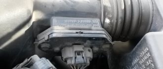
The throttle position sensor is mounted on the throttle body/motor assembly and detects the angle of rotation of the throttle body. This sensor is non-contact. In order to obtain accurate signals even under extreme driving conditions, such as very high and very low speeds, this sensor is designed using the Hall effect.
The throttle position sensor has 2 circuits, VTA1 and VTA2, each of which transmits signals. VTA1 is used to detect the throttle angle, and VTA2 is used to detect errors in VTA1. The sensor signal voltage supplied to pins VTA1 and VTA2 of the ECM varies from 0 to 5 V in proportion to the throttle valve angle.
As the damper closes, the sensor output voltage decreases, and as it opens, it increases. The ECM calculates the throttle angle based on these signals and controls the throttle actuator motor according to the commands. These signals are also used in calculations such as air-fuel ratio correction, power increase correction, and fuel cut control.
| DTC No. | Malfunction | DTC Detection Condition | Faulty area | MIL | Memory |
| P0120 | Throttle/Pedal Position Sensor/Switch "A" Circuit | The output voltage of VTA1 quickly goes beyond the lower and upper fault thresholds for 2 s or more (1-trip detection logic). |
| Lights up | DTC is stored |
| P0121 | Throttle/Pedal Position Sensor/Switch "A" Circuit Range/Performance | The output voltage difference between VTA1 and VTA2 is less than 0.8 V or more than 1.6 V for 2 seconds or more (1-trip detection logic). |
| Lights up | DTC is stored |
| P0122 | Pedal/Throttle Position Sensor “A” Circuit Input Low | The output voltage of VTA1 is no more than 0.2 V for 2 seconds or more (1-trip detection logic). |
| Lights up | DTC is stored |
| P0123 | Pedal/Throttle Position Sensor "A" Circuit Input High | The output voltage of VTA1 is at least 4.535 V for 2 seconds or more (1-trip detection logic). |
| Lights up | DTC is stored |
| P0220 | Pedal/Throttle Position Sensor "B" Circuit | The output voltage of VTA2 quickly goes beyond the lower and upper fault thresholds for 2 s or more (1-trip detection logic). |
| Lights up | DTC is stored |
| P0222 | Pedal/Throttle Position Sensor "B" Circuit Input Low | The output voltage of VTA2 is 1.75 V or less for 2 seconds or more (1-trip detection logic). |
| Lights up | DTC is stored |
| P0223 | Pedal/Throttle Position Sensor "B" Circuit Input High | The output voltage of VTA2 is at least 4.8 V, and the output voltage of VTA1 fluctuates between 0.2 and 2.02 V for 2 seconds or more (1-trip detection logic). |
| Lights up | DTC is stored |
| P2135 | Pedal/Throttle Position Sensor Voltage Correlation “A”/”B” | One of the following conditions is met (diagnosis logic for 1 trip): (a) The difference between the output voltage value of VTA1 and VTA2 is less than 0.02 V for more than 0.5 s. (b) The output voltage of VTA1 is less than 0.2 V and VTA2 is less than 1.75 V for more than 0.4 s. |
| Lights up | DTC is stored |
Technical Tips
- If one of these DTCs is set, check the throttle angle using the GTS. Enter the following menus: Powertrain / Engine and ECT / Data List / All Data / Throttle Position No.1 and Throttle Position No.2.
- The Throttle Position No.1 value represents the magnitude of the VTA1 signal, and the Throttle Position No.2 value represents the magnitude of the VTA2 signal.
For reference (normal condition): 0.5 - 1.1 V 3.2 - 4.8 V Throttle Position No.2 2.1 - 3.1 V 4.6 - 4.98 V
Main indicators and the reason for their occurrence
This list contains the main codes that most often appear on Nissan Almera Classic, G15 and H16 cars. Each error code indicates the occurrence of a particular malfunction:
- P0335: Indicates that the vehicle's crankshaft is not positioned correctly. The information comes from a special sensor;
- P0340: occurs when the vehicle’s camshaft position is incorrect;
- P0120: errors related to the throttle position;
- P1610: occurs due to problems with the electrical supply of the car’s starting system;
- P1612: erroneous function that occurs when the vehicle is blocked;
- P1111: short circuit of the electrical circuits responsible for the valve designed to adjust the intake camshaft;
- U0426: immobilizer lock;
- P1122: Inability to operate the throttle valve device. Most often associated with a short circuit in the electrical circuit;
- P0550: the power steering pressure sensor indicates a pressure level that is higher than normal;
- U1000: indicates that the connection between the vehicle’s on-board computer and the gearbox with the power unit is lost;
- P0051: oxygen sensor failure. The error code indicates a clogged catalyst, however, if there are no other signs of this malfunction, then the problem is in the sensor;
- P1614: erroneous function that occurs when the vehicle's movement is blocked.
The above are the most common errors that occur on the Almera N16, Classic and G15 models. Often the codes indicate a malfunction of the sensor itself, for example, P0335 indicates an error in the vehicle's crankshaft position sensor. If a P0335 reading occurs, replace the faulty sensor and perform a reset. Error P1111 can also occur due to malfunctioning sensor.
Error codes for Nissan Almera H16, G15 and Classic may appear even after the breakdown has been repaired. In this case, you need to be able to reset sensor errors.