As in all other Zhiguli models, the electrical wiring of the penny is made according to a single-wire circuit. Power is supplied to all electrical devices through one wire, and the negative wire is the car body.
Electrical equipment VAZ 2101
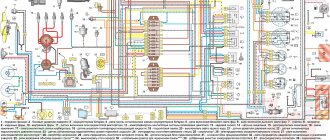
Scheme of a penny in parts:
1 – headlights 2101; 2 – front direction indicators; 3 – side direction indicators; 4 – battery; 5 – battery charge warning lamp relay; 6 – relay for turning on low beam headlights; 7 – relay for turning on the high beam headlights; 8 – generator; 9 – starter; 10 – engine compartment lamp; 11 – spark plugs; 12 – oil pressure warning lamp sensor; 13 – coolant temperature indicator sensor; 14 – sound signals; 15 – ignition distributor; 16 – windshield wiper gear motor; 17 – brake fluid level warning lamp sensor; 18 – ignition coil; 19 – electric motor for windshield washer; 20 – voltage regulator; 21 – heater electric motor; 22 – glove box lighting lamp; 23 – additional resistor of the heater electric motor; 24 – plug socket for a portable lamp; 25 – parking brake warning lamp switch; 26 – brake signal switch; 27 – relay-interrupter of direction indicators; 28 – reverse light switch; 29 – fuse block; 30 – relay-interrupter for the parking brake warning lamp; 31 – windshield wiper relay; 32 – heater motor switch; 33 – cigarette lighter; 34 – lamp switches located in the rear door pillars; 35 – lamp switches located in the front door pillars; 36 – lampshades of VAZ-2101; 37 – ignition switch; 38 – instrument cluster; 39 – coolant temperature indicator; 40 – control lamp for high beam headlights; 41 – indicator lamp for external lighting; 42 – turn signal indicator lamp; 43 – battery charge indicator lamp; 44 – oil pressure warning lamp; 45 – control lamp for parking brake and brake fluid level; 46 – fuel level indicator; 47 – fuel reserve warning lamp; 48 – instrument cluster lighting lamp; 49 – headlight switch; 50 – direction indicator switch; 51 – sound signal switch; 52 – windshield washer switch; 53 – wiper switch; 54 – external lighting switch; 55 – instrument lighting switch; 56 – sensor for level indicator and fuel reserve; 57 – trunk lighting lamp; 58 – rear lights; 59 – license plate light; 60 – reversing lamp
Full size wiring diagram (for printing):
Prevention measures
In order for the VAZ 2101 wiring diagram to always work without failures, it is necessary to follow certain preventive measures:
- First of all, use only fuses that match the rating. If the socket is designed for 10 amperes, you cannot install 15A or 20A fuses in it, this will lead to their accelerated failure. There is also no need to install less powerful fuses, unless as an exception, in order to get to the store and buy the necessary part.
- When installing certain devices, as well as repairing wiring, make sure that the wires are laid correctly and do not come into contact with moving parts. Otherwise, this may lead to their rubbing and, accordingly, further damage.
- Do not use the cigarette lighter splitter by connecting many different gadgets to it. The cigarette lighter itself is designed for a certain power, and if you use a splitter with 2 or more sockets, the load on the device increases significantly. Well, if the fuse ends up blowing, you'll need to replace it, but the result could also be a short in the wiring, which could lead to a fire.
Another version of the VAZ-2101 scheme
Outdoor Lighting
1 – Headlights 2101 2 – engine compartment lamp; 3 – battery; 4 – generator; 5 – reverse light switch; 6 – fuse block; 7 – indicator lamp for external lighting in the instrument cluster; 8 – glove box lighting lamp; 9 – instrument cluster lighting lamp; 10 – plug socket for a portable lamp; 11 – instrument lighting switch; 12 – external lighting switch; 13 – brake light switch; 14 – ignition switch; 15 – lamp switches located in the front door pillars; 16 – lamp switches located in the rear door pillars; 17 – lampshades; 18 – trunk lighting lamp; 19 – rear lights; 20 – license plate light; 21 – reversing lamp
Turning on the headlights 2101
1 – headlights VAZ 2101; 2 – battery; 3 – generator; 4 – fuse block; 5 – headlight switch; 6 – external lighting switch; 7 – ignition switch; 8 – indicator lamp for high beam headlights in the instrument cluster
Direction indicators
1 – sidelights VAZ 2101; 2 – side direction indicators; 3 – battery; 4 – generator; 5 – ignition switch; 6 – fuse block; 7 – relay-interrupter of direction indicators; 8 – indicator lamp for direction indicators; 9 – direction indicator switch; 10 – rear lights
Sound signals 2101
1 – sound signals; 2 – battery; 3 – fuse block; 4 – sound signal switch; 5 – generator VAZ 2101.
Wiper circuit
1 – generator VAZ 2101; 2 – battery; 3 – ignition switch; 4 – windshield wiper switch; 5 – windshield wiper relay; 6 – windshield wiper gearmotor; 7 – thermobimetallic fuse; 8 – windshield wiper switch located in the glass washer pump; 9 – fuse block.
Useful: Pinout of mounting blocks for VAZ cars
Heater fan Zhiguli
1 – generator VAZ 2101; 2 – battery; 3 – ignition switch; 4 – fuse block; 5 – heater switch; 6 – additional resistor; 7 – heater fan electric motor.
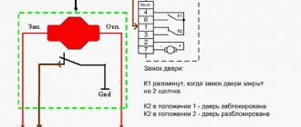
Ignition block diagram
The lock is attached to the steering shaft. Some of the power circuits, which are protected by fuses, are connected directly to the battery, regardless of the position of the key:
- interior lamp;
- sound signal;
- cigarette lighter;
- stop signal.
To adjust the voltage generated by the generator, a relay regulator is provided in the circuit. Its responsibilities include monitoring the voltage at the output of the generator, and when the readings drop, the relay sends a signal to the control lamp located on the instrument panel. If the charging voltage is low, the battery may discharge prematurely and not have time to recharge, which can damage it. If the charging voltage is too high, the electrolyte in the battery may boil, which will also not lead to anything good.
| Key position | Contact under e.g. | Switched circuits |
| "Parking" | "30"-"INT" | Exterior lighting, windshield wiper, heater |
| «30/1» | — | |
| "Turned off" | «30», «30/1» | — |
| "Ignition" | "30"-"INT" | — |
| «30/1″-«15» | Exterior lighting, windshield wiper, heater | |
| "Starter" | «30″-«50» | Starter |
| «30″-«16» |
What is included in the electrical circuit?
First, let's look at the main elements of the electrical circuit and their description for the VAZ 21011 or VAZ 21013.
Important components of the electrical wiring system:
- a rechargeable battery designed to power electrical equipment when the engine is turned off;
- starter unit;
- a generator device, the purpose of which is to power equipment and electrical appliances of a car, as well as charge the battery while driving;
- a block with safety devices that allow you to protect the elements of the VAZ electrical circuit;
- ignition switch.
General wiring diagram for a penny
These are only the main elements of the electrical circuit; the general circuit for a VAZ includes many systems:
- ignition system;
- starter unit connection system;
- activation system for optics, side lights, light alarms and turn signals;
- windshield wiper;
- sound signals;
- heating unit electric motor;
- dashboard.
Scheme of the “penny” brake system
1 – front brake protective housing; 2, 18 – pipelines connecting two cylinders of the front brake caliper; 3 – caliper; 4 – hydraulic drive reservoir; 5 – brake light switch; 6 – parking brake lever; 7 – adjusting eccentrics of the right rear brake; 8 – fitting for bleeding the hydraulic drive of the rear brakes; 9 – pressure regulator; 10 – stop signal; 11 – rear brake wheel cylinder; 12 – lever for manual drive of the pads and expansion bar; 13 – adjusting eccentric of the left rear brake; 14 – brake pad; 15 – rear cable guide; 16 – guide roller; 17 – brake pedal; 19 – fitting for bleeding the hydraulic drive of the front brakes; 20 – brake disc; 21 – main cylinder
The 2101 brake system has two circuits that provide independent drive of the front and rear wheel brakes. Both circuits are driven by a single pedal, which is attached to the front panel of the body using a bracket along with the clutch pedal.
Historical excursion
The first-born of the Volga Automobile Plant, the VAZ 2101, first appeared on domestic roads in 1970. Then, from April to December, more than 21,000 cars were assembled, and in 1974, the annual production amounted to more than 370 thousand cars.
The automaker constantly improved the model, and as a result, the VAZ 21011 was born, for which:
- A more powerful engine with a volume of 1.3 liters was installed (for the VAZ 2101 it was 1.1 liters);
- The interior ventilation grilles were placed on the rear pillars;
- Turn signal repeaters and brake lights with special reflectors were installed.
For reference: the wiring diagram of the VAZ 21011 differed from the “donor” one due to changes in the instrument panel and the addition of a reversing light in the rear of the body.
In addition to the mentioned modification of the VAZ 21011, the automaker released the VAZ 21013 model, and the main difference was:
- 1.2 liter engine;
- suspended gas pedal;
- control of the windshield washer using a foot drive.
For reference: the state advertised the new product in every possible way. This is evidenced by the fact that in videos and films of those years, cars of the VAZ family were seen much more often.
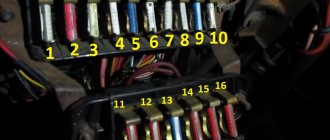
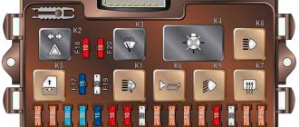
Fuse and relay block VAZ 2101
If short circuits occur in the circuit during vehicle operation, the current strength in the damaged area increases. If the damaged circuit is not disconnected from the network, it can very quickly drain the battery, the wires can overheat, which will cause a greater likelihood of a fire, melting the wires and the upholstery of the car. In order to avoid this, the entire electrical wiring diagram is divided into ten zones, the state of which is controlled by a specific fuse.
Only electromagnetic relays were installed on the penny, and most of them were located under the hood of the car. Only the turn signal relay was installed under the instrument panel.
- Fuse No. 1 (16A) protected the horn, emergency carry socket, interior lamps, cigarette lighter and brake lights;
- Fuse No. 2 (8A) served the electrical circuit of the relay and windshield wiper motor, and the electric motor of the interior heater;
- Fuse No. 3 (8A) – high beam indicator lamp and left headlight (high beam);
- Fuse No. 4 (8A) – right headlight (high beam);
- Fuse No. 5 (8A) – low beam left headlight 2101;
- Fuse No. 6 (8A) – low beam of the right headlight 2101;
- Fuse No. 7 (8A) – side light indicator lamp, left sidelight lamp, right rear side lamp side light, trunk light, rear license plate light, instrument cluster illumination lamp;
- Fuse No. 8 (8A) – side light of the right side headlight, cigarette lighter light, side light of the left rear light, engine compartment lighting lamp;
- Fuse No. 9 (8A) protected the warning lamps on the dashboard: oil pressure lamp, coolant temperature lamp, fuel level and brake fluid level warning lamp, turn indicators and low battery charge lamp;
- Fuse No. 10 (8A) protected the generator excitation winding circuit and the voltage regulator.
Common faults
If there are malfunctions in the electrical circuit, the machine may behave differently:
- The car does not drive or start. Of course, there can be many reasons for such a breakdown, from the battery to the engine. Therefore, you should first diagnose the battery, distributor, and starter unit. In practice, most often car owners are faced with a discharged battery, much less often the generator breaks down, but it also needs to be checked.
- The vehicle is driving, but one or more network components are not functioning correctly. For example, the headlights, dashboard lights, wipers, and rear window heating system do not work. In this case, the unit with safety devices is first diagnosed to detect burnt elements. If all fuses are intact, then you need to check the wiring. Consumers - optics or dashboard bulbs, glass heating systems, windshield wiper motors, etc. - fail much less frequently.
If the car does not start at all, then you need to proceed as follows:
- As stated above, first of all, the battery is diagnosed - maybe the battery is simply discharged.
- Next, you need to check the section of the circuit that goes from the ignition coil to the generator. If there are breaks in this area, the wires will need to be replaced; if the contacts are oxidized, then they are simply cleaned; for this you can use a construction iron brush. Contacts need to be changed if they begin to crumble.
- You also need to check the spark plugs to see if a spark passes through them or not. To do this, you need to pull out one high-voltage wire and bring it to ground - the car body or the cylinder head. When the engine starter is turned with the key, a spark should appear between the wire and ground.
- If there is no spark, then the problem must be looked for either in the coil or in the spark plugs. To check the coil, you will need to diagnose the voltage at its terminals. As for the candles, there should be no signs of damage or soot on them. You can learn in detail about the reasons for the appearance of carbon deposits and cleaning spark plugs in this article (the author of the video is Denis Khafizov).
Functions of electrical wiring of "six" models
Electrical wiring elements, like any other element that is responsible for the functioning of the car, fully have their own characteristics, and the wiring diagram, in turn:
- activates electrical circuits by using the VAZ 2106 ignition switch;
- connects to the battery through a fuse block;
- conducts electric current to key components.
Based on all of the above, you need to start looking for all faults with the ignition switch, because most of the responsibility lies with it. The key unit itself is not only responsible for controlling the entire ignition system in the car, but also performs a security function. It also allows the car to be towed.
Wires for connecting electrical appliances
| Connection type | Section, mm2 | Insulation color |
| Negative terminal of the battery - vehicle ground (body, engine) | 16 | Black |
| Starter positive terminal - battery | 16 | Red |
| Positive contact of the generator - plus battery | 6 | Black |
| Generator - black connector | 6 | Black |
| Terminal on the generator “30” – white MB block | 4 | Pink |
| Starter connector “50” – starter relay | 4 | Red |
| Starter Start Relay - Black Connector | 4 | Brown |
| Ignition switch relay - black connector | 4 | Blue |
| Ignition switch output “50” – blue connector | 4 | Red |
| Ignition switch connector “30” – green connector | 4 | Pink |
| Right headlight plug - ground | 2,5 | Black |
| Left headlight plug - blue connector | 2,5 | Green, gray |
| Generator output “15” – yellow connector | 2,5 | Orange |
| Right headlight connector - ground | 2,5 | Black |
| Left headlight connector - white connector | 2,5 | Green |
| Radiator fan - ground | 2,5 | Black |
| Radiator Fan - Red Connector | 2,5 | Blue |
| Ignition switch output “30/1” – ignition switch relay | 2,5 | Brown |
| Ignition switch contact “15” – single-pin connector | 2,5 | Blue |
| Right headlight - black connector | 2,5 | Grey |
| Ignition switch connector “INT” – black connector | 2,5 | Black |
| Six-pin block of the steering column switch - “ground” | 2,5 | Black |
| Two-pin block of the steering column switch - glove box illumination lamp | 1,5 | Black |
| Glove compartment light - cigarette lighter | 1,5 | Black |
| Cigarette lighter - blue block connector | 1,5 | Blue, red |
| Rear window defroster - white connector | 1,5 | Grey |
How to read electrical diagrams. types of electrical circuits. part 2
Video - Selecting a new battery
Welcome! Battery charge lamp relay - this relay works on the following principle, from the generator, namely from the diode bridge that is located in it, a current of 12 volts is supplied to the relay, the strength of this current is enough to open the two contacts that are located inside the relay, that is, to coil that is located in the relay from the generator (When the car is started), current flows and a core is still installed inside this coil, so this core attracts the plate to itself and thereby the contacts open and the lamp that indicates that the battery charge is low does not light up after that , but if the contacts for some reason do not open, then the lamp that indicates that the battery charge is low will be on constantly, so take this into account and charge the battery first, and then turn your attention to the relay.
Note! In order to replace this relay, you only need one screwdriver!
- Replacing the battery lamp relay
- Additional video clip
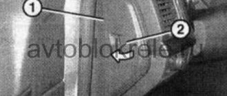
Where is the battery charge lamp relay located? It is located on the right side of the car if you look in the direction of its movement, this relay is actually very easy to find, the main thing is not to confuse it because there are several more relays installed next to it, in general, open the hood of the car and this is attached to the right front part of the body the very relay that bears the index “RS-702” (It is indicated by a red arrow), above this relay there is a cutout in the body, a blue arrow is also directed towards this cutout, so we figured out the location in a few more words, let’s say, we clarified about the index specifically because it is known what inscriptions will remain on the relays that are installed on old cars, you may not actually have them at all, but if you have a relay installed with some other inscriptions (Other markings) and you have driven it for quite a long time and it will has not failed yet (always showed when there is not enough battery charge), then install exactly the same relay and not any other.
When do you need to change the battery charge lamp relay? Regarding the lamp, we would like to talk to you more, there are people who do not know about all the devices that are present in the car, over time a person begins to understand after he studies his car, but at the beginning a lot is not clear, so below is the example of the instrument panel car VAZ 2106, we pointed with an arrow to the very lamp that notifies at the moment when the battery does not have enough charge and needs to be recharged, first of all, charge accordingly, then check the relay (There are some people who never look at the relay and fuses, but they go to a car store and immediately buy a new battery, there is no need to do this, especially if your battery is relatively new), if all the instruments on your panel have gone out, then look at the corresponding fuse, if it is blown, then replace it on new.
Note! When this relay fails, as you already understood, the main malfunction is that the battery charge lamp will light up, which will be indicated by an arrow in the photo above, and it will light up because the contacts will be connected to each other and cannot be disconnected, or some wiring may be connected to the relay jumped you, check them too!
Repair of contact distributor
It is better to repair the distributor-distributor or diagnose it after first removing the device from the engine. Firstly, it will be much more convenient, and secondly, you will have the opportunity to assess the general condition of the distributor.
Dismantling the VAZ 2101 breaker-distributor
To remove the distributor from the engine, you will need two wrenches: 7 and 13 mm. The order of dismantling work is as follows:
- Disconnect the negative terminal from the battery.
- We find a distributor. It is located on the left side of the power plant cylinder block.
- Using your hand, carefully remove the high-voltage wires from the contacts of the cover.
- Disconnect the rubber tube from the vacuum regulator reservoir.
- Using a 7 mm wrench, unscrew the nut that secures the low-voltage wire terminal.
- Using a 13 mm wrench, loosen the nut holding the breaker-distributor.
- We remove the distributor from its mounting hole along with the sealing ring that acts as an oil seal.
- We wipe the lower part of the shaft with a clean rag, removing traces of oil from it.
Disassembly of the distributor, troubleshooting and replacement of failed components
At this stage we will need the following tools and materials:
- hammer;
- thin punch or awl;
- 7mm wrench;
- slotted screwdriver;
- fine sandpaper;
- multimeter;
- medical syringe for 20 cc (optional);
- anti-rust liquid (WD-40 or equivalent);
- pencil and sheet of paper (to make a list of parts that will need to be replaced).
The procedure for disassembling and repairing the distributor is as follows:
Disconnect the device cover from the body. To do this, you need to bend the two metal latches by hand or using a screwdriver. We inspect the cover outside and inside. There should be no cracks or chips on it.
We pay special attention to the condition of the electrodes. If minor traces of burning are found, remove them with sandpaper.
If the contacts are severely burnt, or the cover has mechanical damage, we add it to the list of replacement parts.
We evaluate the condition of the runner. If it shows signs of wear, we add it to the list as well. Otherwise, clean the slider with sandpaper. Turn on the multimeter and switch it to ohmmeter mode (up to 20 kOhm). We measure the resistance value of the slider resistor. If it goes beyond 4–6 kOhm, we add the resistor to the list of future purchases.
Using a screwdriver, unscrew the two screws securing the slider. Let's take it off.
We inspect the weights of the centrifugal regulator mechanism. We check the condition of the springs by moving the weights in different directions. Under no circumstances should the springs be stretched or dangling. If they are hanging out, we make a corresponding entry in our list.
Using a hammer and a thin drift (you can use an awl), we knock out the pin that secures the shaft coupling. We remove the coupling.
We inspect the splines of the distributor shaft. If signs of wear or mechanical damage are detected, the shaft definitely needs to be replaced, so we “take a pencil” to that too. Using a 7 mm wrench, loosen the nut securing the condenser wire. Disconnect the wire. Unscrew the screw that secures the capacitor. Let's take it off.
We carry out diagnostics of the vacuum regulator UOZ. To do this, disconnect the second end of the hose that comes from the “vacuum manifold” from the carburetor fitting. We again put one of the ends of the hose on the fitting of the vacuum regulator reservoir. We place the other end on the tip of the syringe and, by pulling out its piston, we create a vacuum in the hose and reservoir. If you don’t have a syringe at hand, you can create a vacuum with your mouth, after first clearing the end of the hose of dirt. When creating a vacuum, the movable plate of the distributor must rotate. If this does not happen, most likely the membrane in the reservoir has failed. In this case, we add the tank to our list.
Remove the thrust lock washer from the axle. Disconnect the rod.
Unscrew the tank mounting screws (2 pcs.) with a flat screwdriver.
Disconnect the tank.
Unscrew the nuts (2 pcs.) securing the breaker contacts. To do this, we use a 7 mm wrench and a screwdriver, which we use to hold the screws on the back side. We dismantle the contacts. We inspect them and assess their condition. If they are badly burnt, we add the contacts to the list.
Using a slotted screwdriver, unscrew the screws that secure the plate. Let's take it off.
We remove the movable plate assembly with the bearing from the housing.
We check the bearing for play and jamming by shaking and turning the inner ring. If these defects are identified, we prepare it for replacement. We purchase parts according to our list. We assemble the distributor in the reverse order, replacing the failed elements with new ones. There is no need to install the cover and slider yet, since we will still have to set the gap between the contacts.