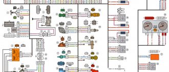
Electrical circuit diagram (1988-2001)
Content
- Front lights;
- Side direction indicators;
- Accumulator battery;
- Battery charge indicator lamp relay;
- Relay for low beam headlights;
- Headlight high beam relay;
- Starter;
- Generator;
- Exterior lights;
- Interior lights;
- Fan motor activation sensor;
- Engine cooling fan electric motor;
- Sound signal;
- Ignition coil;
- Distributor;
- Spark plug;
- Carburetor solenoid valve;
- Coolant temperature indicator sensor;
- Engine compartment lamp;
- Reversing light switch;
- Oil pressure indicator sensor;
- Low oil pressure indicator sensor;
- Insufficient brake fluid level indicator sensor;
- Windshield wiper motor;
- Switch*;
- Windshield washer motor;
- Fan motor activation relay**;
- Voltage regulator;
- Windshield wiper relay;
- Additional fuse box;
- Main fuse box;
- Relay-breaker for hazard warning lights and direction indicators;
- Relay for turning on the heated rear window***;
- Brake light switch;
- Socket for portable lamp****;
- Additional resistor for heater motor;
- Heater motor;
- Heater motor switch;
- Watch;
- Glove compartment lamp;
- Cigarette lighter;
- Hazard switch;
- Instrument lighting regulator;
- Brake fluid level indicator lamp;
- Three-lever switch;
- Ignition switch;
- Rear window heating switch***;
- Rear fog lamp switch;
- External lighting switch;
- Lamp switches located in the front door pillars;
- Motor reducers for electric windows of front doors***;
- Lamp switches located in the rear door pillars;
- Parking brake warning lamp switch;
- Interior lighting lamps;
- Fuel level indicator with reserve indicator;
- Coolant temperature gauge;
- Oil pressure gauge with low pressure indicator;
- Tachometer;
- Parking brake warning lamp;
- Battery charge indicator lamp;
- Carburetor air damper indicator lamp;
- Side light indicator lamp;
- Turn signal lamp;
- Headlight high beam indicator lamp;
- Speedometer;
- Carburetor choke warning switch;
- Left front door power window switch***;
- Front door power window activation relay***;
- Right front door power window switch***;
- Tail lights;
- License plate lights;
- Level indicator and fuel reserve sensor;
- Pads connected to the rear window heating element***;
- Trunk light;
- Rear fog lamp.
The order of conditional numbering of plugs in blocks:
A
- Switch;
b
— Ignition distributor sensor;
V
— Windshield wiper and windshield wiper breaker relay;
G
— Hazard warning and direction indicator breaker relay;
d
— Three-lever switch.* Installed if a vehicle uses a contactless ignition system. In this case, an ignition distributor sensor of type 38.3706 and an ignition coil of type 27.3705 or 027.3705 must be installed.
** Since 2000, the electric motor 12 has not been installed and is switched on directly by sensor-switch 11. In this case, instead of the previously used temperature sensor 11 of type TM-108, sensor-switch 661.3710 is used.
*** Installed on car parts.
**** Not installed since 2000.
Device
If we consider the device, there are two types of temperature sensors.
The first is a thermistor. This is a thermal resistor whose resistance changes as the temperature increases or decreases. The thermistor is located inside a threaded metal housing. There is a plastic tail part on the body. Contacts are installed at the rear. There is one contact (positive) on the tail section. It goes to the dashboard. The role of the second contact is performed by the housing - it is connected to the total mass. The second type of sensor is a special contactor with a bimetallic strip inside. The latter, depending on the heating of the antifreeze, closes or opens.
The first temperature sensor of the VAZ-2106 is used only to display data on the heating of antifreeze in the cooling system. As the temperature rises, the resistance of the sensor changes. A certain voltage is applied to the instrument scale. The device is installed in the engine cylinder block in the channels of the cooling system.
The second temperature sensor is designed a little differently. It also reacts to the temperature of antifreeze or antifreeze, but is designed to turn on the electric fan on the radiator. This sensor is installed on the radiator.
Electrical diagram (1977-1987)
- Front lights;
- Side direction indicators;
- Accumulator battery;
- Battery charge indicator relay;
- Relay for low beam headlights;
- Headlight high beam relay;
- Starter;
- Generator;
- Exterior lights;
- Interior lights;
- Sound signals;
- Engine cooling fan electric motor;
- Fan motor activation sensor;
- Ignition coil;
- Distributor;
- Spark plug;
- Carburetor solenoid valve;
- Coolant temperature indicator sensor;
- Engine compartment lamp;
- Reversing light switch;
- Oil pressure indicator sensor;
- Low oil pressure indicator sensor;
- Insufficient brake fluid level indicator sensor;
- Windshield wiper motor;
- Windshield washer motor;
- Relay for turning on sound signals;
- Fan motor relay;
- Voltage regulator;
- Windshield wiper relay;
- Additional fuse box;
- Main fuse box;
- Relay-breaker for hazard warning lights and direction indicators;
- Brake light switch;
- Plug socket for portable lamp;
- Heater motor;
- Additional resistor for heater motor;
- Watch;
- Heater motor switch;
- Glove compartment lamp;
- Cigarette lighter;
- Hazard switch;
- Instrument lighting switch;
- Indicator lamp for insufficient brake fluid level;
- Three-lever switch;
- Ignition switch;
- Rear fog light switch*;
- External lighting switch;
- Lamp switches located in the front door pillars;
- Front door open alarm lamp switches;
- Front door open warning lamps;
- Lamp switches located in the rear door pillars;
- Parking brake warning switch;
- Interior lighting lamps;
- Fuel level indicator with reserve indicator;
- Coolant temperature gauge;
- Oil pressure gauge with low pressure indicator;
- Tachometer;
- Parking brake warning lamp;
- Battery charge indicator lamp;
- Carburetor air damper indicator lamp;
- Side light warning lamp;
- Turn signal lamp;
- Headlight high beam indicator lamp;
- Speedometer;
- Carburetor choke warning switch; 66 - p
- Parking brake warning relay;
- Tail lights;
- License plate lights;
- Level indicator and fuel reserve sensor;
- Trunk light;
- Rear fog lamp*. The order of conditional numbering of plugs in blocks:
a — Windshield wiper and windshield wiper breaker relay;b — Hazard warning and turn signal breaker relay;
c — Three-lever switch.
* Installed on parts of manufactured cars.
Installing a new unit
Colored electrical diagram gas 2410, 24 and 21: wiring description and electrical diagram
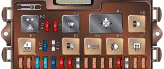
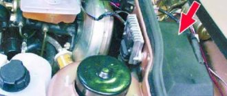
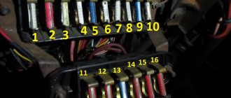
To use fuses of the new type on the VAZ-2106, you need to install a new block instead of the old one. This is not difficult to do, just follow the tips.
Disconnect the negative cable from the battery. Carefully unscrew the old block with a 10mm wrench
Do not allow wires to become disconnected. Pull the block down. Install wires and jumpers according to the diagram. Please note that jumpers are installed only on those wires that come from the engine compartment with voltage. Jumpers are installed between terminals: 3 and 4, 5 and 6, 7 and 8, 9 and 10, 11 and 12, 12 and 13. After this, remove the wires from the old unit one by one and install them on the new one. Check that all connections are correct. Be sure to ensure that the fuses are protecting the circuits they are supposed to.
For example, when you remove F5, the left headlight (low beam) should stop lighting. If the connection is incorrect, check the connections and jumpers
Be sure to make sure that the fuses are protecting the circuits they are supposed to. For example, when you remove F5, the left headlight (low beam) should stop lighting. If the connection is incorrect, check the connections and jumpers.
VAZ 2106 fuse box - replacement
As a rule, replacing fuses on a VAZ 2106 is carried out at the most unexpected moment. After all, they can fail at any moment. For this purpose, the driver should always have a set of new fuses with him, so that if they fail, they can be quickly replaced. But it also happens that repairing fuses alone cannot solve the problem. And then only replacing the fuse box in the VAZ 2106 helps. The old mounting block becomes unusable and thus, only replacing the fuse box in the VAZ 2106 is the only correct solution. Needless to say, after replacing the fuse box on a VAZ 2106, the driver will not be distracted for a long time by troubleshooting problems related to electrical components.
Engine fan diagram
- Electric motor activation sensor;
- Fan motor;
- Motor start relay;
- Main fuse box;
- Ignition switch;
- Additional fuse box;
- Generator;
- Accumulator battery.
Since 2000, a relay for turning on the cooling fan motor has not been installed, and the wires connected to the relay have been removed from the wiring harness. In addition, since 2000, the electric motor has been switched on by sensor type 661.3710. The temperature of closing the sensor contacts is (92±2.5) °C, and the opening temperature is (87±3) °C.
Features of electrical equipment maintenance and replacement of wiring VAZ 2106
Correctly laid wiring around the perimeter of the cabin and under the hood does not require special attention and maintenance. But, after repair work, the cable may be pinched, its insulation may be damaged, which will lead to a short circuit. Poor contact will lead to heating of the cable and melting of the insulation. A similar result will occur if instruments and sensors are installed incorrectly.
A long period of vehicle operation affects the condition of the wire insulation, which becomes hard and brittle, especially under the influence of significant heat in the engine compartment. Damage caused by damaged wires is not easy to find. If the damage is in the public domain without braiding, repairs are carried out without dismantling the wires.
When replacing one wire, you should label the ends of the wires located in the blocks, making a connection drawing if necessary.
Main stages of wiring replacement:
- new wiring harness for the VAZ 2106 model;
- disconnected battery from the vehicle network;
- disassembly of the instrument panel;
- torpedo disassembly;
- removing seats;
- removal of the noise-insulating coating for convenient access to the wiring harness;
- clean out corrosion that may cause poor contact;
- It is not recommended to leave exposed wires at the end of the work.
The wiring replacement procedure should not be carried out without an electrical diagram for connecting the devices to avoid confusion during installation work.
When replacing a single wire, a new one should be of the same color and size. After replacement, you should test the corrected wire with a tester connected to the nearest connectors on both sides.
Precautionary measures
Before performing work, you should disconnect the battery and insulate the sharp edges of the technological holes in the car body in places where the wires will pass to prevent a short circuit.
Low/high beam circuit
- Headlights;
- Fuse box;
- Speedometer with high beam headlight indicator;
- Relay for low beam headlights;
- Headlight switch;
- Headlight high beam relay;
- Generator;
- External lighting switch;
- Accumulator battery;
- Ignition switch.
Diagram of brake lights, reverse lights, side lights, license plate lighting
- Front lights with side light lamps;
- Accumulator battery;
- Generator;
- Engine compartment lamp;
- Fuse box;
- Brake light switch;
- Plug socket for portable lamp;
- Reversing light switch;
- Ignition switch;
- External lighting switch;
- Speedometer with side light indicator;
- Trunk light;
- Rear lights with parking lights, brake lights and reversing lights;
- License plate lights.
Hazard and turn signal diagram (1977-1985)
- Headlights with direction indicator lamps;
- Accumulator battery;
- Generator;
- Side direction indicators;
- Main fuse box;
- Additional fuse box;
- Ignition switch;
- Hazard switch;
- Turn signal switch;
- Relay-breaker for alarm and direction indicators (23.3747);
- Speedometer with turn signal indicator;
- Rear lights.
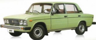
General information about the brand
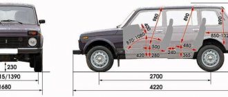
Domestic cars of the 2106 brand were manufactured for the purpose of operating on roads equipped with improved surfaces, regardless of weather conditions. The cars are equipped with a four-door all-metal sedan body.
Cars are equipped with carburetor gasoline engines, four-speed or five-speed gearboxes. There is an independent spring front suspension; The rear suspension is dependent spring. The car's braking system is dual-circuit; there are disc brakes on the front wheels.
The rear ones are equipped with drums. Cars of the VAZ 2106 family were equipped with radial tubeless tires. The steering column has an anti-theft device that is built into the ignition switch.
The modification range of the VAZ 2106 family includes:
- VAZ 2106, 21065-00 - equipped with a model 2106 engine;
- 21061, 21065-01 – equipped with a model 2103 motor;
- 21063 – there was an engine from 21011.
- Car brand 21065 is the luxury version of this family. It has the following differences from the 2106 model: it is equipped with a five-speed gearbox and a final drive with a gear ratio of 3.9. Some cars were equipped with a Solex-type carburetor and a contactless ignition system. The car's electrical equipment is complemented by an electrically heated rear window, halogen headlights and a rear fog lamp. The body has been modified: the upholstery and seat headrests have been updated; The car is supplemented with bumpers of the 2105 model. Spare parts for the presented vehicles are available everywhere. In addition, the electric power steering is a kind of “novelty”, so to speak, the trends of the 21st century are making themselves felt. Thanks to this, car maintenance and repairs are not a big problem.
Hazard and turn signal diagram (1985-2001)
- Sidelights;
- Side direction indicators;
- Accumulator battery;
- Generator;
- Ignition switch;
- Main fuse box;
- Additional fuse box;
- Relay-breaker for hazard warning lights and direction indicators (231.3747);
- Turn signal warning light in the speedometer;
- Hazard switch;
- Tail lights;
- Turn signal switch in a three-lever switch.
How to prevent wiring malfunctions?
What you need to consider to avoid problems with electrical circuits:
- The procedure for replacing wires must be performed with electrical appliances and the battery turned off.
- Disconnecting and connecting battery contacts is only allowed with the ignition off.
- When checking the wiring, a short circuit must not be allowed; this can lead to damage to electrical appliances.
- Do not use metal tools to remove safety devices.
- Do not disconnect the battery while the engine is running. As a result, the car owner may face the problem of failure of the voltage regulator and other components of the circuit.
- If the functionality of the diode bridge of a generator set is being checked, the use of a megohmmeter powered from a network with a voltage of more than 12 volts is not allowed.
- When welding the body, the battery and generator must be disconnected. It is also necessary to disconnect the ECU, if present, from the power supply.
- It is not allowed to carry out repairs or replace wiring when the engine is turned off.
- Periodically recharge the battery and clean its terminals.
Loading …
Windshield wiper and washer diagram
- Washer motor;
- Windshield wiper and washer switch;
- Windshield wiper relay;
- Wiper motor;
- Fuse box;
- Ignition switch;
- Generator;
- Accumulator battery.
Since 1985, a reusable thermobimetallic fuse has been installed in the wiper motor. It is designed to protect the electric motor from overloads.
How to check?
Since the VAZ-2106 coolant temperature sensor is extremely simple, the methods for diagnosing it are extremely simple. But before diagnosing the element, you should inspect the wiring and its integrity. You can also check whether voltage is coming to the sensor.
The most accurate way to check functionality is to measure the resistance using a multimeter. But during the measurement process, the element will have to be boiled in water. As the temperature changes, the resistance of the sensor will change. But since in the VAZ-2106 the DTOZH does not affect anything, it is easier to simply replace the faulty element. Moreover, its price is not higher than two hundred rubles.
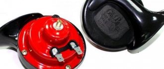
Sound signal circuit
- Sound signals;
- Relay for turning on sound signals;
- Sound switch;
- Fuse box;
- Generator;
- Accumulator battery.
Since 1993, one sound signal of type 20.2721-01 has been installed on cars, and it is turned on without an auxiliary relay “2”. There are two wires leading to the signal: red from plug “A” of the fuse box and gray with a black stripe from the horn switch.
Reasons for repairing the ignition switch
Care and maintenance of a VAZ 2106 with an injection engine
The ignition switch of the “six” has 4 modes with different functionality:
- Mode “0” allows you to power only wires 30 and 30/1. Other functions are disabled.
- Mode “I” makes it possible to operate the running lights, fog lights, wiper drive, and heater motor.
- Mode “II” - in this case, the electrical wiring on the VAZ 2106 activates the turn signals, instrument panel and ignition system.
- The “III” position of the key provides power to terminals 30/1 and 30-INT. The car starter is working.
Underhood electrics of the VAZ six
Replacing the ignition switch with your own hands may be necessary for several reasons:
- Firstly, this is possible in case of loss of keys.
- Secondly, over time, the ignition switch cylinder wears out, and this affects engine starting.
- In addition, there may be problems with the contact wire group, which can lead to a short circuit.
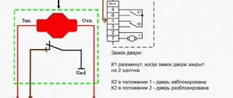
On cars of the “classic” family, the location of the lock is below and to the left of the steering wheel. Also see the article about the restoration of domestic classics.
And it consists of the following elements and parts:
- lock body;
- contact disk;
- locking rod;
- roller and contact sleeve;
- block.
Checking the operation of the distributor
Window lifters
- Main fuse box;
- Power window relay;
- Left door power window switch;
- Right door power window switch;
- Right door electric window motor reducer;
- Left door electric window motor reducer;
- Additional fuse box;
- Ignition switch;
A - to terminal -30- of the generator;B - to the instrument lighting switch; B - conventional numbering of plugs in the gear motor block.