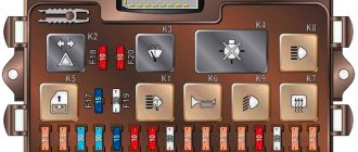
Relay block
In the cabin, under the panel, near the driver’s left foot, a relay block is mounted on the wall. Depending on the configuration and year of manufacture, different arrangements of elements are possible.
p, blockquote 11,0,0,0,0 —>
p, blockquote 12,0,0,0,0 —>
I can find it here:
p, blockquote 13,0,0,0,0 —>
- rear window defroster relay
- headlight high beam relay
- low beam headlight relay
- wiper relay
- heater motor relay
- horn relay
- fog light relay
- turn signal relay.
GAZ 3110 Volga sedan (GMOD SMR SCARS) by DigitalExplorations on DeviantArt
Ported from one of the larger GMOD Russian SCARS packages that exist. The original source is unknown, but variations of this model can be found on many free 3D model sites on the Internet. As with many GMOD SCARS models, you can change the color or texture of the body by simply replacing the "skin" texture.
The GAZ 3110 Volga turned out to be the most successful of the second generation of Russian sedans of the GAZ 31 series and the first truly popular car in the GAZ 31 line. It was still borrowed from the time-tested GAZ 24, like the entire GAZ 31 series, from which it inherited name Volga, but it was improved as much as its old but reliable frame and design could be. With a completely new modern body design, a truly comfortable interior (which was new for Russian cars at the time, as they will tell you), a decent transmission and modern suspension, and at a price that is affordable for most working Russians, in fact
itself (especially the low-end budget version, only for base models), it turned out to be much better than expected. It was seen as an inexpensive alternative to expensive imports from Europe and America, and even performed well on the resale market. It was also available in both petrol (petrol) and diesel models straight off the production line. Its only shortcomings were those that affected all Russian-built cars in the 1990s: poor assembly, faulty electronics and poor service from the manufacturer. However, the time for change was approaching the classic Volga family, and it was clear that the basic design had almost reached the limits of possibility of modification. There would be another attempt to make a modern Volga (GAZ 31105), but that was all. The GAZ 3110 sedan ceased production in 2004, although a station wagon or station wagon version will remain in production until 2010.
To download, click the "Download" button in the upper right corner.
.
Read also
Military options and equipment on the UAZ-469 vehicle
Military options and equipment on the UAZ-469 car With the start of serial production, the UAZ-469 immediately became the main light multi-purpose vehicle of the Soviet Army and the armed forces of all fraternal and allied countries. In the 1970s, it was exported to 70 countries. These cars were
External glass and porcelain insulation of electrical equipment and switchgear
External glass and porcelain insulation of electrical equipment and outdoor switchgear Question. How should the specific effective creepage distance of external porcelain insulation, as well as insulators of flexible and rigid external open conductors, be selected? Answer. Must be selected based on data
Placement and installation of electrical equipment
Placement and installation of electrical equipment Question. What electrical equipment and devices can be installed in EMF? Answer. Can be installed: electric machines; electric machine converting units; starting and control devices for
Placement of electrical equipment
Placement of electrical equipment Question. What conditions must the placement of electrical equipment of adjustable electric drives satisfy? Answer. Must satisfy the general requirements set out in chapters 4.3, 5.1, 5.3 of these Rules, as well as the technical specifications for
Classification and marking of explosion-proof electrical equipment according to GOST 12.2.020-76
Classification and marking of explosion-proof electrical equipment according to GOST 12.2.020-76 Question. What are the established explosion protection levels for electrical equipment? Answer. The following levels have been established: electrical equipment of increased reliability against explosion - explosion-proof
4.3.1. General overview of motivational processes in quality management
4.3.1. General overview of motivational processes in quality management The concept of “motive” is often used to denote such psychological phenomena as aspiration, desire, intention, fear, etc., which are reflected in a person in the form of readiness for activities leading to
Electrical faults
Malfunctions of electrical equipment The battery requires attention The battery discharges slowly during operation. The starter cranks the engine at a low speed. Current leakage through damaged insulation of any wire or device - from here
13.2.3. General overview of the state of nanoparticle production
13.2.3. General overview of the state of nanoparticle production The commercial use of any method must be economically justified. In laboratory conditions, scientists have been able to develop many interesting and beautiful methods for synthesizing nanopowders, but many of them
Phosphates and total phosphorus
Phosphates and total phosphorus Phosphorus is an essential element for life, but its excess leads to accelerated eutrophication of water bodies. Large amounts of phosphorus can enter water bodies as a result of natural and anthropogenic processes - surface erosion
General diagram of electrical equipment
General diagram of electrical equipment Electrical equipment of cars is a complex system of interconnected electrical alarms, ignition, fuses, instrumentation, and connecting wires. Rice.
GAZ 3110 | Possible starter malfunctions and ways to eliminate them
| Possible starter malfunctions and ways to eliminate them | |
| Cause of malfunction | Remedy |
| The starter and traction relay do not turn on | |
| Battery is very low | Replace the battery or charge it |
| Battery terminals have oxidized | Clear pins |
| The ignition and starter switch is faulty | Connect a test lamp to terminal <50> of the ignition switch and the housing. If the lamp does not light up when turning the key to the <start> position, replace the switch |
| Additional relay faulty | Use a test lamp to check the presence of voltage at terminal <30> of the additional relay |
| Broken wire from the additional relay to the starter traction relay | Reconnect the test lamp to pin <87> and the housing. If the lamp does not light up when turning 1 key to the <start> position, replace the additional relay |
| Unreliable contact with the housing of the holding winding of the traction relay | Use a test lamp to check the serviceability of the wire; if necessary, repair it. Replace the relay |
| The traction relay turns on, but the armature does not rotate | |
| Battery is very low | Replace battery or charge |
| Battery terminals have oxidized | Clear pins |
| Burning of the starter switch valves in the traction relay | Remove the switch cover and clean the contacts |
| Starter brushes stuck or worn out | Remove the protective cap, eliminate the hang-up or replace the brushes |
| Jamming of the starter armature as a result of separation of its windings | Turn on the driver's lamp, turn on the starter. If the light of the lampshade decreases greatly (with a working battery and wiring), this indicates separation of the armature winding or the armature touching the poles. The starter needs to be repaired |
| The traction relay turns on and off quickly (knocking) | |
| Battery is very low | Replace the battery or charge it |
| Battery terminals have oxidized | Clear pins |
| Unreliable contact with the housing of the holding winding of the traction relay | Replace relay |
| Misadjustment of additional relay | Check and, if necessary, adjust the additional relay |
| The starter turns on, but the engine does not turn over | |
| Freewheel slipping | Replace coupling |
| The starter turns on, but the gear does not engage | |
| Incorrect adjustment | Make adjustments |
| The teeth of the drive gear ring are clogged | Refill the teeth or replace the drive |
| The buffer spring on the starter drive is weak | Replace spring |
| The starter rotates the engine at low speed and abnormal noise. | |
| The armature catching on the poles as a result of bearing wear | Replace bearings |
| The starter does not turn on after starting the engine | |
| Drive jamming on the splined part of the shaft | Clean the shaft from dirt and remove yellow deposits from bearing wear. Lubricate the shaft |
| Sintering of additional relay contacts or starter switch contacts in the traction relay | Immediately turn off the ignition, disconnect the battery and repair the fault. |
Replacing wiring
Wiring for a Gazelle 406 engine with pinout of ECU connector terminals.
Changing all the electrical wiring of a Gazelle when replacing an engine from 402 to 406 is of course not impractical.
The fact is that on newer versions of Gazelles, the connection diagram of certain devices also changed:
- Gazelle 406 wiring is integrated into the standard electrical system in the engine compartment;
- electronic components and control devices are connected using terminals;
- The voltage and correct connection are checked using testers.
After assembling the wiring into a single whole, its functionality is checked. Subsequently, the operation of the power unit is adjusted.
Conclusions: Replacing the power unit inevitably affects the change in the standard electrical wiring of the car
That is why it is important to have a visual aid at hand when carrying out such an operation, and the Gazelle’s factory wiring diagram will allow you to avoid mistakes
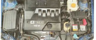
Features of electrical equipment
The GAZ electrical equipment diagram includes the following subsystems:
- engine starting system;
- ignition, which includes a distributor, spark plugs, coil, etc.;
- external car lighting, including fog optics, light alarms and turn signals;
- dashboard;
- interior lighting, as well as all devices installed in it;
- heating system - stove;
- windshield wiper unit;
- headlight adjustment device;
- microprocessor-based engine control system;
- mounting block of safety devices.
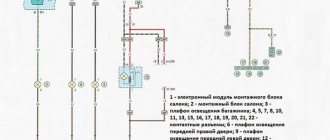
Photo gallery “Subsystem connection diagrams”
Gas fuel pump fuse 31105
Gas 31105 cars with Chrysler engines plus restyling were considered.
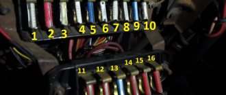
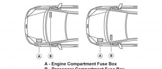
fuse box in the cabin.
In cars manufactured before May 2007, the fuse box is located above the glove compartment behind a plastic cover. To access the fuses, you need to slide the cover with the word “Volga” to the right, then insert your finger into the opened hole and pull the cover towards you to remove it.
diagram of the location of fuses in the cabin block (until May 2007)
Left block fuses
Heater electric motor (air conditioning)
High beam right headlight
Main beam of the left headlight, indicator lamp for turning on the main beam of headlights
low beam right headlight
Low beam left headlight
Rear fog light
Cigarette lighter, horns, horn relay
Fuel pump, exhaust oxygen concentration sensor
Engine management system
Turn signals, turn signal relays, turn signal warning lamps
Engine compartment lamp, glove box and interior lamps
The engine control unit
Right block fuses
Heating (air conditioning) and ventilation control unit, rear window heating relay, rear window heating (1 mode)
Reversing light, speed sensor, instrument cluster, cooling motor relay
Left side lights, side light warning lamp, fog light relay
Heated rear window (mode 2) and mirrors
Anti-lock brake system (ABS)
Electric drives and heated exterior mirrors
Electric locking drives
Right side lights, headlight washer relay, trunk light, license plate lights, instrument lights, cigarette lighter, switches. Electric headlight corrector
In Gas 31105 (Chrysler) cars produced after May 2007, the fuse box is located under the instrument panel behind the cover.
To access the fuses, remove the decorative cover.
diagram of the location of fuses in the block.
Upper block fuses
Heater (air conditioning) electric motor
High beam right headlight
High beam of the left headlight, indicator lamp for turning on the high beam of the headlights
Low beam right headlight
Low beam of the left headlight, indicator lamp for turning on the low beam of headlights
Rear fog light
Cigarette lighter, horns, horn relay, instrument cluster clock
System, engine control, diagnostic connector
Turn signals, turn signal relays, turn signal warning lamps
Engine compartment lamp, glove box and interior lamps
The engine control unit
Lower block fuses
Heating (air conditioning) and ventilation control unit, heater valve, central light switch, front lamp, interior temperature sensor, fog lamp relay
Reversing light, speed sensor, instrument cluster
Left side lights, control pump for turning on side lights
Heated rear window and mirrors
Anti-lock brake system (ABS)
Electric exterior mirrors
Electric locking drives
Right side lights, trunk light, license plate lights, instrument lighting pumps, cigarette lighter switches Electric headlight corrector
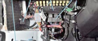
Relay unit in the passenger compartment Gas 31105 (Chrysler).
located on the left behind the facing.
- starter relay;
- relay for turning on fog lights;
- rear fog light relay;
- windshield wiper relay;
- relay for low beam headlights;
- headlight high beam relay;
- relay for turning on sound signals;
- relay for switching on electric heating of rear window glass
Turn signal relay.
located on the turn switch.
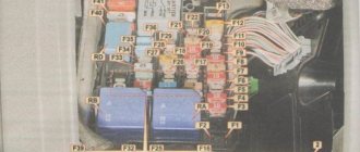
Fuse box in the engine compartment Gas 31105 (Chrysler).
where it is located - on the left mudguard under the hood.
diagram of the location of fuses in the block.
#1 60 A protects the anti-lock brake system (ABS) circuit;
No. 2 at 60 A - almost all power supply circuits for vehicle consumers, except for the starter circuit and those protected by the rest of the fuses in the unit; fuse
No. 3 at 40 A - power supply circuits for vehicle lighting and light signaling;
No. 4 at 90 A - circuits of the battery, generator, electric headlight washer (if equipped) and the power circuit of the electric radiator fan of the engine cooling system.
On vehicles not equipped with anti-lock brakes and manufactured before July 2006, fuse No. 1 was not used.
Since July 2006, through this fuse, terminal “A29” of the engine control unit has been connected to the generator, through which the function of controlling the excitation current of the generator is carried out (voltage adjustment in the vehicle’s on-board network).
Fuel pump relay and main relay of the engine management system.
located under the hood on the cooling system tank mounting bracket.
1- engine control system relay
2 - fuel pump relay
The relays on the left are located on the left mudguard.
- radiator electric fan relay for the engine cooling system,
- fuel injection system relay,
- air conditioning fan relay,
- The air conditioning compressor clutch relay is located on the left mudguard of the engine compartment and is attached to the power steering reservoir mounting bracket.
The fuel pump relay is installed in the engine compartment on the same bracket as the diagnostic connector and the main relay.
You will need a 10" socket wrench (head).
1. Turn off the ignition and remove the negative terminal of the battery.
2. Align the mounting bolt and remove the relay.
3. Remove the wire block from the relay terminals.
4. Install the relay in the reverse order of removal.