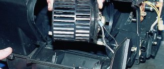
Dear readers and subscribers, it’s nice that you continue to study the structure of cars! And now we bring to your attention the electronic fuel injection system, the operating principle of which I will try to explain in this article.
Yes, we’ll talk about those devices that have replaced time-tested carburetor power systems from under the hoods of cars, and we’ll also find out how much modern gasoline and diesel engines have in common.
Electronic fuel injection system
Perhaps we would not have discussed this technology if a couple of decades ago humanity had not become seriously concerned about the environment, and toxic exhaust gases from cars turned out to be one of the most serious problems.
The main drawback of cars with engines equipped with carburetors was incomplete combustion of fuel, and to solve this problem, systems were needed that could regulate the amount of fuel supplied to the cylinders depending on the operating mode of the engine.
Thus, injection systems or, as they are also called, injection systems, appeared in the automotive arena. In addition to improving environmental friendliness, these technologies have improved engine efficiency and power characteristics, becoming a real boon for engineers.
Today, fuel injection is used not only on diesel, but also on gasoline units, which undoubtedly unites them.
They are also united by the fact that the main working element of these systems, no matter what type they are, is the nozzle. But due to differences in the method of fuel combustion, the designs of injection units for these two types of engines, of course, differ. Therefore, we will consider them in turn.
Principle of operation
Injection engine units with a single nozzle operate according to the following scheme:
- the engine starts;
- sensors read and transmit information to the control unit;
- real data are compared with reference data, the moment of opening the injector is calculated;
- a signal is transmitted to the electromagnetic coil;
- gasoline is supplied to the manifold for mixing with air;
- The fuel mixture is supplied to the cylinders.
Functioning of a unit with distributed injection:
- air is supplied to the motor;
- sensors determine volume, temperature, crankshaft performance, damper position;
- the volume of fuel for the supplied air is calculated by the control unit;
- a signal is sent to the injectors;
- they open at the programmed time.
- gasoline is mixed with air in the manifold, and the mixture is supplied to the cylinders.
Training video on the operating principle of distributed injection
The operating principle of direct injection depends on the method of mixing gasoline with air :
Layer-by-layer mixing is used at medium speeds, the air supply speed is high, gasoline is supplied to the cylinder through the nozzle, and lights up after mixing with air.
When mixing the stoichiometric type, the process starts the moment you press the gas. The throttle valve opens, gasoline and air are supplied at the same time and burn completely.
When mixing homogeneous type, air movement is first created in the cylinders, then gasoline is injected.
Video explanation of the operating principle of a direct injection injector
The operation of the combined system depends entirely on the load on the motor:
- direct injection starts during startup, warm-up, maximum load, the number of injections depends on the mode;
- distributed injection starts while driving at medium speed with frequent stops.
With distributed injection, the direct nozzles periodically open. This prevents them from clogging.
Not only gasoline engines, but also diesel engines are equipped with injection systems. The first ones can be called spark engines, since the mixture of gasoline and air is ignited by a spark.
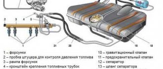
Injection systems and gasoline
Electronic fuel injection system. Let's start with gasoline engines. In their case, injection solves the problem of creating an air-fuel mixture, which is then ignited in the cylinder by a spark from the spark plug.
Depending on how this mixture and fuel is supplied to the cylinders, injection systems can have several varieties. Injection happens:
- central;
- distributed;
- direct;
- combined.
Central injection
The main feature of the technology, located first in the list, is one single injector for the entire engine, which is located in the intake manifold. It should be noted that this type of injection system in its characteristics is not very different from a carburetor, therefore today it is considered obsolete.
Distributed injection
Distributed injection is more progressive. In this system, the fuel mixture is also formed in the intake manifold, but, unlike the previous one, each cylinder here boasts its own nozzle.
This variety allows you to experience all the advantages of injection technology, therefore it is most loved by automakers and is actively used in modern engines.
Direct injection
But, as we know, there are no limits to perfection, and in pursuit of even higher efficiency, engineers developed an electronic fuel injection system, namely a direct injection system.
Its main feature is the location of the injectors, which, in this case, extend their nozzles into the combustion chambers of the cylinders.
The formation of the air-fuel mixture, as you might already guess, occurs directly in the cylinders, which has a beneficial effect on the operating parameters of the engines, although this option is not as environmentally friendly as that of distributed injection. Another noticeable drawback of this technology is the high requirements for the quality of gasoline.
Combined injection
The most advanced in terms of the level of emissions of harmful substances is the combined system. This is, in fact, a symbiosis of direct and distributed fuel injection.
Main sensors
- Crankshaft position sensor (Hall sensor). Lets the block know the location of the pistons in the cylinders. The essence of the work is that a gear located on the motor shaft moves near a magnet. Its teeth distort the magnetic field, creating pulses in the coil. The ECU reads these pulses and determines the position of the crankshaft. If this sensor fails, then you will not be able to drive your car to the service station.
- Air flow sensor (DRV). There are two types of such sensors, one measures the mass and the other the volume of intake air. The mass air flow sensor takes measurements and sends them to the ECU. There is a heating element in the flow, the temperature of which is automatically kept at the desired level. The heavier the air, the more current must pass through it to maintain the optimal temperature. Therefore, the ECU determines the mass of intake air by current strength. As for the volume sensor (DOVR), it is designed like this. In the flow where the air intake passes, a partition is installed that opens under the pressure of air. The ECU determines the position of the damper using a potentiometer. During a malfunction, the sensor parameters are not taken into account, and the calculation is carried out according to the indicators of the emergency table.
Injector ECU
- Throttle position sensor . Controls the position of the throttle valve, due to which the ECU can correctly reduce or increase fuel consumption.
- Oxygen sensors (lambda probe). Calculates the amount of oxygen in exhaust gases. Based on its readings, the ECU detects a lean mixture and makes corrections.
- Coolant temperature sensor . Lets the computer know when the motor has reached the desired operating temperature. At the time of the accident, the sensor parameters are ignored; the temperature is taken from the table based on the engine operating time.
- Manifold absolute pressure sensor (MAP) Analyzes the air and its quantity in the intake manifold; this indicator is needed to determine the amount of energy conducted.
- Voltage sensor . Monitors the voltage of the vehicle's on-board network. Based on its readings, the controller can increase or, conversely, decrease engine idle speed.
- Knock sensor . It is a high-frequency microphone that picks up unacceptable sound vibrations in the motor. Receiving abnormal sounds, the controller automatically adjusts the advance angle.
We recommend: Hydraulic clutch release drive: purpose, design and bleeding
How are diesels doing?
Let's move on to diesel units. Their fuel system is faced with the task of supplying fuel under very high pressure, which, when mixed in the cylinder with compressed air, ignites itself.
There are a lot of options for solving this problem - direct injection into the cylinders is used, and with an intermediate link in the form of a preliminary chamber; in addition, there are various designs of high-pressure pumps (HHP), which also adds variety.
However, modern motorists prefer two types of systems that supply diesel fuel directly to the cylinders:
- with pump injectors;
- Common Rail injection.
Pump nozzle
The pump-injector speaks for itself - in it the nozzle that injects fuel into the cylinder and the injection pump are structurally combined into one unit. The main problem with such devices is increased wear, since the pump injectors are connected by a permanent drive to the camshaft and are never disconnected from it.
Common Rail system
The Common Rail system takes a slightly different approach, making it more preferable. There is one common injection pump, which supplies diesel to the fuel rail, which distributes fuel to the cylinder injectors.
This was just a brief overview of injection systems, so, friends, follow the links in the articles, and using the Engine section, you will find all the injection systems of modern cars to study. And subscribe to the newsletter so as not to miss new publications in which you will find a lot of detailed information on car systems and mechanisms.
See you again!
Tags engine
Injection duration and flow rate curve (injection)
The term "feed rate" describes the curve of the amount of fuel injected into the combustion chamber as a function of the crankshaft or camshaft angle (crankshaft or camshaft angles, respectively).
One of the main parameters influencing the injection intensity curve is the injection duration. It is measured in crank or cam angles or in milliseconds and is the period during which the injector is open and fuel is injected into the combustion chamber. The figure shows how the amount of fuel injected is started by the pump camshaft and how the fuel is injected from the injector ( as a function of the camshaft angle). It can be seen that the pressure characteristic and injection rate curve vary greatly between the pump element and the injector, and that they are influenced by the parts that determine the injection (cam, pump element, injection valve, fuel line (feed line) and injector).
Different diesel engine systems require different injection times in each case. Engines with direct injection require approximately 25 - 30° of crankshaft rotation at a certain number of revolutions, and engines with pre-chamber require a crankshaft rotation angle of 35 - 40°. The injection duration at a 30° crankshaft rotation corresponding to a 15° camshaft rotation means an injection duration of 1.25 milliseconds for an injection pump speed of 2000 rpm.
To keep fuel consumption and sulfur emissions low, the injection duration must be determined as a function of the operating point and depends on the start of injection. At the start of injection, only a small amount of fuel should flow, while at the end a large amount of fuel is required. The injector should then close as quickly as possible. This feed rate curve will result in a slow increase in compression pressure. The combustion will thus be “soft”. In direct injection engines, combustion noise is noticeably reduced if a small portion of the fuel injected into the combustion chamber is finely atomized before the main injection.
This injection method remains very expensive. Engines with a split combustion chamber (pre-chamber or swirl chamber) use needle throttling injectors. These injectors produce a single jet of fuel and determine the flow rate curve. The injectors control the outlet cross-section as a function of the injection valve (discharge valve) stroke.
Secondary injection (or so-called "dripping") is particularly undesirable and occurs when the injector quickly re-opens after it has closed, and it injects poorly prepared fuel later in the combustion process. This fuel does not burn completely or does not burn at all and exits through the exhaust gases as unburned hydrocarbons.
Quick-closing nozzles prevent this “dripping.” The "dead volume" at the bottom of the injector seat produces an effect similar to "dripping". Fuel vapors accumulated in this volume exit into the combustion chamber after combustion is completed and also enter the exhaust gases, where they increase emissions of unburned hydrocarbons. The smallest “dead volume” is obtained with injectors with a seat with holes.
Typical malfunctions of injection engines. Practical advice
Modern cars with injection systems, powerful and economical engines are good for long trips. But it is there, far from “advanced” service stations and qualified specialists, that the “Check Engine” alarm (Check Engine is a light on the instrument panel indicating that the ECU (electronic control unit) has detected problems in the engine control system) especially frightens travelers. Some panic and, fearing irreversible consequences, take the cable out of the trunk. Others, on the contrary, are cold-blooded: since the engine is running, it means the lamp “just made a mistake” and “will go out on its own” - you can drive at the same pace.
The ability to recognize the symptoms of typical injection ailments and imagine what a burning yellow lamp threatens will help save nerves, money, time and the engine. If the engine is working properly, the “Check Engine” signal should go out 0.6 seconds after starting - this is enough for the self-diagnosis system to make sure that everything is in order. If, nevertheless, the light continues to light, then there is a malfunction that can be identified using a special motor tester at a service station or on your own. As for “on your own,” this is a superficial diagnosis that can give an approximate definition of the malfunction; the reason for this is the lack of special measuring instruments and parameters of the injection system components. But on the road, in the absence of a service station, this can help you and give you confidence that the car will still get to its destination.