1 – label. 2 – factory hole. 3 – additional holes.
If, when adjusting the valve timing, it is necessary to rotate the camshaft(s) in the direction of its rotation (clockwise), then the sprocket(s) must be installed on one of the additional holes with a positive offset, located to the right of the factory hole, if - against clockwise, then install the sprocket(s) on one of the holes with a minus offset, located to the left of the factory hole. The selection of a hole on the sprocket with the required displacement value is made depending on the deviation of the angular position of the cam from the nominal value. When installing the sprocket on the additional hole, the factory timing mark 1 on the sprocket will not coincide with the top plane of the cylinder head.
Photos of protractors and settings
As an example, consider adjusting the valve timing with the template arrow reading 23° for the intake cam and 16° for the exhaust cam. These angles exceed the nominal values for the intake and exhaust cams by 3°, which is greater than the ±2° tolerance. With these readings of the angular position of the cams and taking into account that when the engine is running, the camshafts rotate clockwise, observing from the side of the crankshaft pulley, the opening of the intake and exhaust valves will begin to occur somewhat ahead of the factory values of the valve timing. To adjust the phases, in this case, it is necessary to turn the camshafts counterclockwise and, when installing the sprockets, use an additional hole with a minus angular offset, with an offset value of 2 ° 30 ° (the first hole located to the left of the factory hole). Then continue the work in the following sequence:
1 . Turn the key to “27” and install the exhaust camshaft so that the template arrow is opposite the 19° protractor mark.
2. Throw the chain over the sprocket and orient its first accessory hole, located to the left of the factory hole, so that it is in front of the camshaft pin, and the drive target leg (in the area of the middle guide) is tensioned. To install the sprocket on the camshaft flange and pin, slightly turn the camshaft clockwise using the square wrench. After installing the sprocket, turn the camshaft counterclockwise to tighten the drive chain, while the arrow of the template installed on the cam should show 19 ° ± 2 °.
3. Install the intake camshaft so that the template arrow is opposite the 20° protractor mark.
4 . Install the sprocket on the intake camshaft in the same way as the exhaust camshaft sprocket, using the same additional hole. In this case, with the leading branch of the chain tensioned (in the area of the upper damper), the arrow of the template mounted on the cam should show 20 ± 2 °.
5 . Screw in the sprocket mounting bolts (key “12”) first by installing the fuel pump drive eccentric (mod. 4063) into the sprocket seat of the intake camshaft.
6. Disassemble and assemble (“charge”) the hydraulic tensioner, install it in the hole in the cylinder head, and close the lid.
7. Using a screwdriver, press the hydraulic tensioner plunger from the heel side of the shoe and bring the hydraulic tensioner into working condition (“discharge”).
8 . Check that the valve timing is set correctly by turning the crankshaft two turns in the direction of rotation and aligning the marks on the damper pulley and the chain cover. Check using a protractor and a cam template as described above. The arrow of the template installed on the intake cam should show 20 ± 2 °, and on the exhaust cam it should show 19 ′ ± 2 ′. If this condition is not met, it is necessary to repeat the installation of the valve timing.
9 . Screw in and tighten the bolts securing the camshaft sprockets to a final torque of 5.6 – 6.2 kgf.m.
10 . Install the upper and middle chain guides by screwing in and tightening the fastening bolts to a torque of 2.0 – 2.5 kgf.m (wrench “6” for bolts with a hexagonal socket, torque wrench with a head “6”).
eleven . Reassemble the engine in reverse order.
Search
Procedure for replacing the timing chain ZMZ-406 Volga GAZ-31105 (video)
The dream of our fathers and grandfathers is the Volga. Not long ago, an old friend of mine visited us in his favorite GAZ 31105. There seemed to be extraneous noise from the timing drive, as well as increased consumption and poor throttle response, which condemned the timing chains. So, GAZ 31105, engine 406 - timing chain replacement.
Let's say right away what we need: engine oil with a filter and a sump gasket, it would be better if it was cork, high-temperature sealant, gray 999 from ABRO, kerosene and a metal brush for washing parts. I have only seen a clean engine It’s not for nothing that they say: “If the Volga doesn’t leak oil, it means it doesn’t exist.” Another set of keys and sockets with a reinforced 36mm, a 6mm hexagon, a lot of rags, instant coffee and several sausage sandwiches. As well as patience and a great desire to carry out this procedure yourself, since the temptation to entrust this to someone else is very great. After reading the article to the end, you will understand why.
Most importantly, this is a complete kit for repairing the gas distribution drive of ZMZ-405,406,409 engines - this is its official name. It must include the following ingredients:
- Two chain tensioners.
- Two hydraulic chain tensioners.
- Two drive chains, small and large. For ZMZ-406 there are 70 and 90 links, for ZMZ-405 there are 72 and 92 links.
- Three chain guides.
- Gaskets for the upper and lower chain covers, pump and hydraulic tensioner covers, as well as two soundproofing ones.
- Sprockets of the crankshaft, camshaft, intermediate shaft, drive and driven with a locking plate.
This is what he looks like.
And here is the patient himself.
Under the hood there really is a ZMZ-406 engine.
Signs of breakdown of the gas distribution mechanism
Among the main signs of malfunctions in the gas distribution mechanism are:
- significant drop in engine power;
- the appearance of popping noises in the intake and exhaust manifolds;
- reduction of compression in the cylinders (normal value is above 10 kg/sq. cm).
If the circuit is faulty, it will begin to make a characteristic noise. The cause of breakdowns may be a loose fit of the valve plates to the seats. This provokes the formation of carbon deposits and breaks the springs. If you replace the chain in a timely manner, all these troubles can be avoided.
We finished the examination, let's start strength exercises
First, remove the engine protection and mudguard. photo report on replacing the timing chain and how to set the ignition. Engine 405 euros. Drain the antifreeze and oil from the engine. How to change the timing belt on a Ford Focus 2+ 1.6l engine. 115hp What tools will you need, what difficulties will there be when replacing the timing belt yourself. Remove the upper radiator pipe.
Disconnect all interfering pipes.
We remove the wiring harness to the side. We remember or sketch the location of the connectors on the ignition coils.
Using a 12mm socket, unscrew the eight bolts in a circle holding the valve cover and remove the last one.
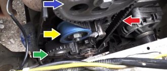
While the service belt is tense, loosen the three bolts on the 10th pump pulley.
We loosen the bolt by 13, the tension roller and unscrewing the bolt by 10, we loosen the tension of the auxiliary belt.
Remove the service belt, roller and coolant pump pulley.
We unscrew the four screws of the upper timing case cover and remove the last one.
We remove the generator along with the triangular plate.
Unscrew bolt 10 of the crankshaft position sensor.
We move the sensor to the side so that it does not interfere.
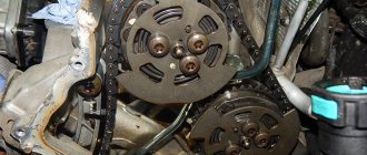
Using a 36mm socket, use the pulley bolt to turn the crankshaft clockwise until the marks on the camshafts point to top dead center.
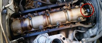
The mark on the intake camshaft should be level with the top edge of the cylinder .
Likewise for the exhaust camshaft.
Theory
All 16-valve engines are distinguished by one feature - VERY accurate timing is required. For this operation, two tools are required - a TDC indicator and a phase meter. Sometimes on websites there is a popular name - a protractor for camshafts. For more complex settings and completely non-standard camshafts, such tools are no longer used. It is necessary to work with three indicators. But we're talking about a standard engine. In the Euro-0 and Euro-2 options, everything could be set up without instruments at all, but these are not our working methods. As the hero of one film said: a lot of work has been done, but this cannot continue. When I started working with engines of this family, I honestly did not expect that they would be so capricious in tuning, especially in the Euro-3, Euro-4 modifications. The most popular operation today, as I call it, is tuning light. The scope of work includes: replacement of hydraulic compensators, spark plugs, rollers, belt and correct installation of camshafts ZMZ 406, 405, 409.
GAZELLE - installing camshafts according to marks
Ideal phase. In this video I will tell you how to exhibit
ignition according to
marks
. Subscribe to my channel
We unscrew the crankshaft pulley bolt, having previously locked the crankshaft. To do this, the assistant in the cabin engages fifth gear and presses on the brake with all his might, while we, with a slight movement of the hand, using a meter-long pipe and a 36mm socket, unscrew the bolt. We remove the crankshaft pulley, you will have to suffer because it sits tightly on the shaft.
Loosen the clamps of the pump pipes.
Use a 6mm hex to unscrew the four screws on the front side of the pump and a 12mm wrench to one on the back side and remove the coolant pump.
Unscrew the two bolts of the upper hydraulic tensioner cover. Since the tensioner in a discharged state will put pressure on the cover, we hold it so that it does not jump out.
Remove the cover and the hydraulic tensioner itself.
Likewise for the bottom one.
We unscrew the six bolts on the 14 amplifier and remove it. The oil pan mounting nuts were hidden under it.
Use a hexagon to unscrew the remaining screws of the front timing cover (5 pieces), as well as everything that holds the oil pan (11 screws and 4 nuts).
The pallet goes down about two centimeters, the beam does not go any further. But this is enough to pull out the old gasket and, remembering the kind words of the engineers from Gorkov, clean the adjacent surfaces before installing a new gasket.
This is the terrible picture that appears before our eyes.
Now remove the lower timing cover.
Using a hexagon, unscrew the screws of the upper damper and remove it.
Same with the second one. It will come off along with the chain.
The camshafts have a special 30 mm square so that the shafts can be held when unscrewing the sprocket bolt. We hold the shafts with a 30 wrench and unscrew the camshaft sprockets with a 17 wrench.
We remove the camshaft sprockets and the chain with the damper.
Use a hexagon to unscrew the chain tensioner fastening and remove it. Same with the bottom one.
We bend the edges of the locking plate and use a 12mm wrench to unscrew the bolts securing the intermediate shaft sprocket. We remove it together with the chain. Then use a hexagon to unscrew the two bolts of the lower damper and remove it.
Remove the retaining ring and the crankshaft sprocket. In the photo the ring is slightly shifted for clarity.
A two-legged puller is best suited for this.
And here is the secret why we change as a set. If you look at the sprockets, you can immediately see the difference, so the old chain will not fit the new sprockets and vice versa.
Now that everything that bothered us has been dismantled, we can wash all the removed parts and the cylinder block, at least from the front.
Malfunctions and their elimination
Like any technical product, the Gazelle-Business motor is susceptible to breakdowns. Sometimes it needs repairs for various reasons. The most common problems that arise are:
- The motor does not start. Most likely there is no fuel supply to the injectors. It is necessary to use the appropriate fuel, rinse and clean the fuel intake.
- The tightness of the pipeline between the tank and the electric pump is broken. The connection points should be checked and the tightness restored.
- There are problems with the control electronics. It is necessary to replace faulty parts of the unit.
- Poor power delivery indicates problems in the electronic control system. After testing, it is necessary to replace the unusable element.
- The fine filter is clogged. In this case, the filter element must be replaced.
- Air appears in the fuel block. It is necessary to check and ensure the tightness of the system.
- If problems are detected in the fuel pump, the faulty injectors should be replaced.
Let's start assembly
We put on a new crankshaft sprocket and immediately set a mark.
Then we screw on the lower damper and tensioner and install a new chain.
We install the intermediate shaft and set a mark. We bend the edges of the locking plate. We put a chain on it and lubricate everything with new engine oil. The right side of the chain should be taut.
Let's check again that the marks match.
We put the upper chain on the intermediate shaft and install the damper. Lubricate everything with clean oil.
The exhaust camshaft sprocket, so that the right branch is tensioned, and the mark on the sprocket is at the level of the upper edge of the cylinder . Same with the second camshaft.
We install the hydraulic tensioner and screw on the cover. We unscrew the plug and sharply press the hydraulic tensioner with a screwdriver until it discharges. But before you set the timing marks on the ZMZ-406, the 406 engine is carburetor. When discharged, it will push out the screwdriver and tighten the chain.
the marks again .
Carefully place the front cover, having previously lubricated the gaskets and all adjacent surfaces with sealant. Putting the cover on is not easy because you need to hold the tensioner and make sure that the marks do not get lost. We turn the crankshaft two turns and, if the valves do not meet the pistons and all the marks are in place, we put everything else in the reverse order of removal. You are interested in: timing marks gazelle 405 photo. Photos on this topic are selected here, but relevance is not guaranteed. Fill with oil and antifreeze and start the engine.
Markers for setting the ignition on the 405 ZMZ timing engine
Manufacturers put timing marks on ZMZ 405 engines. These marks are needed in order to correctly align the crankshaft and camshaft after changing the chain in the distribution mechanism of the power unit. Because if installed incorrectly, the engine may fail. A major overhaul of the ZMZ 405 engine will be expensive for the car owner.
- Engine timing chain marks 405
- Replacing the timing chain of a gazelle 405 engine
- Why does the timing chain fail?
- Replacing a 405 gazelle chain: how to determine the need
- How to replace the timing belt Gazelle 405
- How to set timing marks Gazelle 405
- Where is the chain located
- Signs of breakdown of the gas distribution mechanism
- Gazelle installation of camshafts by marks
- Ideal phase
- Timing marks and tightening
- Conclusion
VESKO-TRANS.RU
AutoNews / Reviews / Tests
How to set the ignition on a Gazelle 405 Engine
Adjusting and installing the ignition ZMZ 402: secrets and tips
engine is one of the products of the Russian auto industry, widely used in the automotive industry. These power units were equipped with certain models of Volga, UAZ, and Gazelle cars. To ensure normal engine performance, the ignition
. In this article we will tell you how to install a distributor on a 402 engine and what should be taken into account when performing the task.
Characteristics
The injection engine in the Gazelle Business car has the following technical characteristics:
- Engine type is a four-stroke gasoline unit with 4 cylinders.
- The injection system is microprocessor controlled with ignition and air supply.
- Cylinder volume (cubic cm) - 2,464.
- Standard power at a rotation speed of 4.5 thousand revolutions is 214 Nm.
- The filter is an air dry replaceable element.
- The cooling system is closed type with forced circulation.
- Generator - with a built-in unit and voltage controller.
- Sensors for monitoring system overheating and oil pressure.
- The starter is a remote, electromagnetic version with a gearbox.
Technically, the 2.46-liter engine with a power of 140 horsepower allows the car to overtake or perform sharp maneuvers when fully loaded.
What you need to know
In order to properly configure and adjust the ignition of the ZMZ 402, you need to know some nuances about the operation of the power unit . Such motors have a non-contact distributor installed, supplemented by a control signal generator and mounted advance regulators - vacuum and centrifugal (video author - smotri Vidik).
The distributor is designed to perform certain functions:
- determines the moment of spark occurrence;
- transmits high voltage signals through the cylinders of the power unit
, taking into account the order of their operation.
For the correct distribution of impulses, a slider mounted on the mechanism pulley is used. The slider is equipped with a resistor and is designed to suppress interference. The switching device performs the function of opening the ignition coil winding circuit, converting control signals from the regulator into short-circuit current signals.
KEY-DOP
To correctly install the ignition on a 402 engine , it is necessary to take into account the system characteristics presented below:
- the order of operation of the cylinders is first the first, then the second, then the fourth and third;
- the rotor of the distribution element rotates counterclockwise;
- on a centrifugal device the advance angle is from 15 to 18 degrees;
- on a vacuum device this indicator is from 8 to 10 degrees;
- the play on the NW should be no more than 0.8 mm;
- the resistor resistance value should be from 5 to 8 kOhm;
- the SZ resistance parameter should vary around 4-7 kOhm;
- in the stator winding the resistance level should be no more than 0.45 and no less than 0.5 kOhm.
General information
We can carry out the adjustment process on our own, that’s for sure. However, if you are the owner of a top-end car whose starting system has failed for some reason, it is better to contact a service center.
On the contrary, if it is a used Renault or our domestic Gazelle car, there is no need to think about it. You need to undertake the adjustment procedure yourself.
In order to correctly set the ignition on an injection system, you will need a laptop with diagnostic software, a set of keys and screwdrivers, and a measuring tester.
As you know, the injector is controlled electronically. She, in turn, will obey the BC installed on the machine. In order to carry out the procedure efficiently, you first need to test the connection of all electronic elements.
- Turn on the ground and ignition.
- The electric fuel pump is automatically turned on.
If it does not pump fuel, you need to immediately diagnose the operation of the relay that monitors and controls the pump.
- If you do not find a problem with the operation of the engine itself, you need to move on to checking the throttle assembly. Pay special attention to the degree of throttle openness.
- Check the condition of the sensors.
All final parameters must be compared with those set by the manufacturer. For example, the on-board network must have a current value of 12 volts, and the degree of openness of the damper must be at least 90 percent. If this is not the case, the throttle actuator is adjusted.
It may also be necessary to adjust the valves in order to accurately operate the valve timing. The procedure is carried out according to plan, every 20,000 km.
Valve adjustment can be carried out ahead of schedule if a characteristic clatter of the engine is heard.
Valve adjustment is always carried out using feeler gauges and other required tools and devices. It is better to entrust this procedure to specialists at a car service center.
How to install the ignition yourself?
How is the ignition installed on the ZMZ 402? The crankshaft must be placed in a position that corresponds to an advance angle of 5 degrees.
You need to set the moment like this:
- On the power unit, we combine the average mark on its shaft on the cylinder head cover, that is, at the end of the compression stroke on cylinder 1.
- If the distributor has not been removed from the power unit , the compression stroke on cylinder 1 can be detected by opening its cover. It is necessary that the slider be installed opposite the internal contact, which is connected via a cable to the spark plug. If it is not possible to determine the compression in this way, you can dismantle the SZ installed in the first cylinder. After this, the hole will need to be covered with a rag, or better yet, with paper. The crankshaft needs to start rotating, and at the moment when the paper plug is knocked out by the air flow, the compression stroke begins.
- Now you will need a 10mm wrench - with its help you need to slightly loosen the octane corrector bolt, but you do not need to unscrew the screw itself.
- Next, you should set its scale to zero, this is approximately the middle of the scale.
- After completing these steps, using a 10mm wrench, you need to loosen the bolt that secures the octane corrector plates.
- Now you need to rotate the distributor body so that the marks are aligned. In particular, we are talking about the red mark located on the rotor, as well as the risk on the stator. When the installation of the device drive is completed, the distributor must be held in this position with one hand, and the bolt must be tightened with the other hand.
How to set the ignition on a gazelle 405 engine.
Many people set the ignition to a strobe light. Sometimes setting the ignition timing does not produce results - the engine continues to stall and not operate at full power. The reason is the inoperability of the distributor as a whole. The problem can be solved by replacing or repairing the distributor.
Repair and adjustment
Incorrectly adjusted Gazelle-405 fuel pumps (injector) provoke an increase in fuel consumption and the appearance of unnatural black smoke. To eliminate the malfunction, it is necessary to adjust the pump operation and injection angle. A non-working injector requires timely replacement. And blue smoke from the exhaust system indicates excessive oil consumption. This may be due to worn piston rings that need to be replaced.
If the guide bushings or crankshaft bearings are worn, they must be replaced with new elements. Too white smoke from the exhaust system indicates an increase in fuel consumption. In this case, the injector may need to be replaced. If not (injector), you need to check the thermostat (replace if necessary) or clean the fuel intake, ensure normal fuel supply to the injectors.
Checking the spark plugs yourself
According to the wiring diagram for engines 405, 406 and 409, spark plugs are used to transfer spark from the switchgear to the engine cylinders. If the operation of the SZ is disrupted, this may affect the quality of the motor as a whole.
To check devices you will need an assistant:
- You need to disconnect the high-voltage wire from the first SZ.
- Using a key, the product is unscrewed from its seat.
- One end of the device from the electrode side should be brought to the engine or metal on the car body, the distance between the electrode and the ground should be about 1-2 mm.
- The assistant then turns the starter to try to start the engine. If at the moment of cranking a spark jumps between the electrode and the body, this indicates that the product is operational. In the same way, you need to check each SZ. Please note that problems with spark supply can also be caused by improper operation of the distributor, as well as damage to high-voltage wires.
Site about off-road vehicles, SUVs, off-road vehicles
During operation of the ZMZ-409 engine, as a result of natural elongation of the chains, wear of the camshaft drive sprockets of the gas distribution mechanism, or due to improperly carried out repairs of the timing drive, a significant deviation of the valve timing from the nominal values is possible.
Checking the valve timing and, if necessary, adjusting them is necessary in the case of a clear decrease in the traction properties of the engine, its unstable operation in all modes, or a strong increase in fuel consumption.
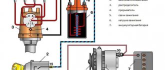
The correct installation of valve timing is one of the factors affecting the power, torque and economic performance of the engine. To check the valve timing, a kit of equipment developed at the car plant is used, which includes:
- Protractor.
— Template with cam profile and arrow.
In the ZMZ-409.10, ZMZ-40904.10 and ZMZ-40905.10 engines, the coordinates of the profile points 252 should be used for both camshafts. In the ZMZ-4091.10 and ZMZ-40911.10 engines, the coordinates of the profile points 240 should be used for the intake camshaft, and for the exhaust camshaft - coordinates of profile points 252.
— A jig for drilling additional holes for the pin in the camshaft sprockets.
For driving camshafts with bushing chains.
For driving camshafts with toothed chains.
Checking valve timing on ZMZ-409, camshaft cam angles for drives with bushing and toothed chains.
The valve timing is checked with the engine installed in the vehicle. To check the valve timing from the ZMZ-409 engine, it is necessary to remove the valve cover, disconnecting all the wires and hoses, and install the piston of the first cylinder at TDC of the compression stroke, turning the crankshaft in the direction of rotation, clockwise, until the marks on the crankshaft damper pulley match with an indicator ridge in the form of a tide on the chain cover. Rotating the crankshaft counterclockwise is not permitted.
In this case, the camshaft cams of the first cylinder and the marks on the camshaft sprockets must be located according to the diagram.
If the tops of the cams and marks are located inward, then it is necessary to turn the crankshaft one more revolution. Precise installation of the piston of the first cylinder at TDC can be carried out using a dial indicator, which is installed and secured in the spark plug hole of the first cylinder.
Checking the angular position of the first cam of the intake camshaft.
Place a protractor behind the first cam of the intake camshaft - view “A” in the diagram.