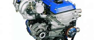
In order for an engine with a 402 carburetor from a UAZ to work normally, you need to set the ignition correctly, and how to do this will be described in this article. Many novice car owners incorrectly set the marks when changing the timing belt, so our auto service often receives engines that require major repairs. This should not be allowed, since, firstly, it is costly for the owner. Secondly, such a breakdown leads to the purchase of a new engine. But this doesn't happen often.
Ignition system elements
The elements of ignition of fuel in the engine are dominant. Through it, the power unit is started. A couple of types of ignition systems have been developed for gasoline engines:
- contact;
- contactless.
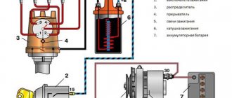
The elements for igniting a combustible gasoline engine are given in the list:
- distributor or spark breaker. Installed to determine the moment in ignition when a spark appears and transfers high voltage to the engine cylinders. The device combines its work with the movement of pistons in the cylinders;
- coil;
- switch. This part extinguishes the flow of electricity to the coil winding and turns the signal from the regulator into a current signal;
- candles;
- lock;
- starter;
- resistance. Sometimes they add.
Attention! On an engine from a Gazelle or UAZ, a non-contact ignition system is used. A generator is added to it to control signals and devices to regulate advance: vacuum and centrifugal.
Experienced mechanics advise reading the characteristics given below to set the ignition correctly:
- The operation of the engine cylinders is carried out in this way: one, two, four, three;
- the rotor device always rotates counter-minutewise;
- the centrifugal part has a lead angle of eighteen degrees;
- the vacuum part has a lead angle of ten degrees;
- SZ play does not exceed 0.8 mm;
- R resistor does not exceed 8 kOhm;
- R SZ no more than 7 kOhm;
- R in the stator winding – 0.5 kOhm.
Now let's talk about how ignition of fuel in the power unit works.
Maintenance and Prevention
The operating principle of an injection engine is based on controlling the fuel supply using electronics. Due to this, the engine requires preventive maintenance approximately every 12 thousand kilometers (according to the manufacturer’s recommendation). At the same time, the oil and filter are replaced.
If the Gazelle-405 (injector engine) operates in intensive mode, it is recommended to service the engine every 8-10 thousand kilometers, since under heavy loads the oil changes its chemical composition faster and loses its properties.
It is recommended to adjust the valves with the installation of appropriate washers every 15 thousand. In addition, it is necessary to check the gas distribution mechanism, since a broken belt can lead to deformation of the valves, which can lead to costly repairs or even replacement of the cylinder head.
Source
How the ignition system works
The fuel mixture is ignited as follows:
- The driver turns the key in the lock.
- Current from the battery goes to the starter.
- The crankshaft begins to rotate.
- The distributor turns on.
- Current flows to the coil.
- It passes through the switch to the distributor.
- The last device distributes the current among the spark plugs.
Similar article Adding oil to a hot and cold engine
This ensures proper ignition in the engine. However, there are early and late arson. Then we can talk about malfunctions of the power unit.
Early ignition
Early ignition occurs before the cylinder piston approaches top dead center. Gasoline with air and oil is ignited while the piston is still moving. Such problems arise due to an incorrectly set ignition angle.
Experienced mechanics identify such a breakdown by the following signs:
- the power unit does not start immediately;
- unstable operation of the engine when idle at traffic lights, when the car is standing still;
- the appearance of a chattering sound that does not go away when the load increases;
- When disassembling the engine, mechanics discover carbon deposits on the spark plugs. This means that the fuel does not burn out completely;
- increased fuel consumption;
- dark smoke from the muffler pipe.
These are all signs of pre-ignition. Let's look at what happens when the ignition is slow and ignition does not occur on time.
Late ignition
If the marks are set incorrectly on 402 ZMZ engines, late ignition occurs when the piston has already passed the top point. The car owner can notice this by a drop in power with increased gasoline consumption.
Experienced mechanics notice late ignition by the following signs:
- candles turn gray or white;
- the engine begins to heat up very much, although the cooling system is in order;
- The motor may stall when the load increases.
Correct ignition adjustment and adequate placement of marks will help to cope with the problems described above.
Powertrain capabilities
Owners of the Gazelle-405 car are impressed by the fuel-injector engine, especially in terms of fuel consumption. It ranges from 8 liters on the highway to 13 in the combined cycle when driving around the city. Oil is also used sparingly: approximately 100 grams per thousand kilometers. In a single-point system, the manifold is equipped with only one injector for all cylinders. In a distributed block, each of them has its own collector. And with direct injection, fuel is supplied directly to the cylinders, just like a diesel engine.
Procedure for adjusting the ignition system
To correctly adjust the ignition, you need not only to set the advance angles, but also to position the marks correctly. By the way, if the car owner does not understand and does not understand the design of the engine, then it is better to give this work to experienced mechanics in the service center.
Let's look at all the nuances of ignition adjustment.
Label matching
To correctly compare the marks and set the engine ignition, do the following:
- Set the first cylinder to top dead center.
- The crankshaft is turned so that the mark on its pulley aligns with the mark on the cylinder head.
To do these steps, you will need to remove the spark plug from the first cylinder and plug the hole with a rag. Rotate the crankshaft until this rag is removed by air, which creates pressure inside the cylinder.
Similar article Reasons for the formation of emulsion in the engine
Such actions will help to find the end of the compression stroke, otherwise the top dead center of the cylinder.
Advance angle adjustment
To set the ignition timing of the ZMZ 402, you need to do the following:
- Slightly unscrew the octane number corrector bolt on the distributor.
- Set the advance angle on the engine to the center of the scale.
- Slightly unscrew the screw that secures the plates of the octane correction device.
- Rotate the distributor until the red mark on the rotor head is directly in front of the mark on the stator.
The car owner must then hold the engine distributor with one hand. And with his second hand he will tighten the screws. This is how the ZMZ 402 ignition is set.
Checking the correct installation of the ignition
Now the car owner will only have to check that the ignition is installed correctly. Whether he installed the ignition correctly or not can be determined as follows:
- Accelerate the vehicle to 60 kilometers per hour.
- At this speed, press the gas pedal sharply.
- Detonation will occur within three seconds.
- If it does not continue in the future, then the engine ignition was set correctly.
Attention! Experienced mechanics set the ignition in the engine using a strobe light.
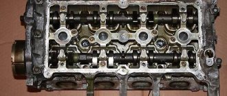
Block head
All engine modifications were equipped with one head, which complied with Euro 2 requirements. With the introduction of additional Euro 3 requirements, it was refined and improved. It is not interchangeable with the previous model.
The new head does not have idle system grooves; now their functions are assigned to an electronically controlled throttle. The front wall of the part is equipped with holes for attaching the protective chain cover, and on the left side there are ebbs for mounting the intake system receiver brackets. The part has pressed cast iron inserts and valve guides. The latter do not require periodic adjustment, since they are driven by cylindrical pushers with hydraulic compensators. The modernized ZMZ-406 head has decreased in weight by 1.3 kilograms. When installing it on the engine, use a metal multilayer head gasket.
How to install the ignition yourself
You can install the ignition yourself. For such a procedure you will need a standard set of tools. If there is a strobe, then that's good. The tool will allow you to set the correct ignition of the mixture, so as not to endlessly crawl under the hood.
And the procedure is done as follows:
- Warm up the engine to 80 degrees. This is its operating temperature.
- The instrument is connected to the on-board computer.
- The distributor cap lock will need to be unscrewed.
- The signal sensor must be placed on the high-voltage wire of the first cylinder.
- If there is an engine vacuum corrector hose, it must be plugged.
- Light from a strobe light is directed onto the engine crankshaft pulley.
- Start the engine and leave it idling.
- Rotate the distributor body.
- Combine marks.
- Tighten the clamp.
This completes the installation procedure.
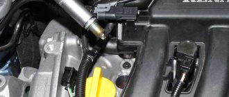
Connecting high-voltage wires ZMZ 405, ZMZ 406
ZMZ carburetor and Euro-2 engines are equipped with a DIS (Double Ignition System) ignition system.
The DIS system uses ignition coils with two high-voltage wires. Each coil operates a corresponding pair of cylinders.
The first coil works with 1 and 4 cylinders, the second coil works with 2 and 3 cylinders.
How to connect the ignition coils?
The ignition coil of cylinders 1 and 4 is located closer to the intake manifold, the coil of cylinders 2 and 3 is closer to the exhaust manifold.
Low-voltage coil wires must be connected to the coil in pairs. The pair of wires for coil 1-4 is slightly shorter than the pair of wires for coil 2-3.
Within the pair, it does not matter which contact is connected to which wire - the coils are non-polar. Also, within the pair, it does not matter which high-voltage wire goes to which cylinder.
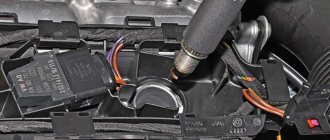
Let's look at an example (see photo)
Coil 1 control (cylinders 1 and 4) – green and yellow wires. This pair connects strictly to the coil of cylinders 1 and 4!
Low voltage circuit - polarity is not important - can be connected:
Option 1: The top coil contact is yellow, the bottom contact is green.
Option 2: The top coil contact is green, the bottom contact is yellow.
High voltage outputs – polarity is not important – can be connected:
Option 1: Top outlet for cylinder 1, bottom outlet for cylinder 4.
Option 2: Top outlet for cylinder 4, bottom outlet for cylinder 1.
Coil 2 control (cylinders 2 and 3) – blue and yellow wires. This pair is connected strictly to the coil of cylinders 2 and 3! Further - similar to pair 1-4 - the polarity within the pair is not important.
The determining factor when connecting pairs of low-voltage and high-voltage wires to the corresponding ignition coil is the correctness of their routing. The wires should not be too tight, bent too much, and should not rub against fixed parts of the engine or other wires.
Another article about high-voltage wires ZMZ 405, 406 - read so as not to repeat this mistake.
Source
Installation of distributor with drive
Installation of the distributor with the drive is carried out as follows (all work is carried out with the power unit running):
- Turn the distributor counterclockwise.
- Be prepared for the engine speed to increase.
- If the car owner continues to crank the engine distributor, the power unit may stop working stably.
- When the engine speed drops, you need to turn the distributor clockwise.
Similar article Technical characteristics and reviews of the Chrysler engine for the Volga and Gazelle
To test whether everything has been done correctly, it is recommended to sharply accelerate the car or, conversely, brake sharply and stand for a while. At the same time, the operation of the engine should be stable, and it should not stall.
Characteristics
The injection engine in the Gazelle Business car has the following technical characteristics:
- Engine type is a four-stroke gasoline unit with 4 cylinders.
- The injection system is microprocessor controlled with ignition and air supply.
- Cylinder volume (cubic cm) - 2,464.
- Standard power at a rotation speed of 4.5 thousand revolutions is 214 Nm.
- The filter is an air dry replaceable element.
- The cooling system is closed type with forced circulation.
- Generator - with a built-in unit and voltage controller.
- Sensors for monitoring system overheating and oil pressure.
- The starter is a remote, electromagnetic version with a gearbox.
Technically, the 2.46-liter engine with a power of 140 horsepower allows the car to overtake or perform sharp maneuvers when fully loaded.
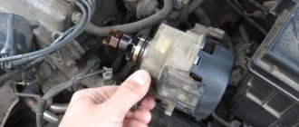
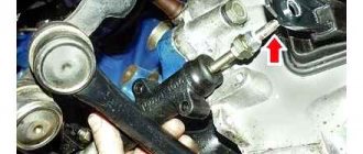
Removing the distributor assembly with the oil pump drive
To carry out repair work on the distributor on a Gazelle or UAZ engine, you will need to remove it. This is done this way:
- Remove the cover along with the wires located there.
- Remove the vacuum regulator hose.
- Dismantle the fastening of the low-voltage wire.
- Remove the octane corrector fastenings. To do this, use a key of ten. And to dismantle the low-voltage wire, use a seven key.
- Finally, remove the engine distributor itself.
This task is easy and does not require special skills to complete. However, the car owner must have an understanding of the design of the motor. Installation is carried out in reverse order. It must be remembered that the distributor can only be installed in one position.
If you need to remove the oil pump with distributor, you need to do this:
- Remove the engine distributor cap. Remove high voltage wires.
- Now you need to remember how the slider is located relative to the body.
- Dismantle the vacuum hose and switch wire.
- Unscrew the two fastening nuts. The key is used for thirteen.
- Dismantle the distributor sensor and oil drive.
Remove the gasket on the engine and put in a new one if that's the problem. If the position of the engine crankshaft remains unchanged, install everything in the reverse order. If even small changes occur, then first the piston is moved to top dead center. Align the mark on the crankshaft pulley with the mark on the cylinder head. The cylinders must be closed.
Then the distributor is installed.
Oil
The ZMZ-406 power plant is equipped with a combined lubrication system. Under the influence of pressure, the process of lubrication of the piston pins, connecting rod and main bearings of the crankshaft occurs, the support points of the camshafts, the hydraulic valve drive, the intermediate shaft and the driven gear of the oil pump are lubricated. All other parts and elements of the motor are lubricated by spraying oil.
Closed crankcase ventilation with forced exhaust of gases.
Source
What you need to know
In order to properly configure and adjust the ignition of the ZMZ 402, you need to know some nuances about the operation of the power unit. Such motors have a non-contact distributor installed, supplemented by a control signal generator and mounted advance regulators - vacuum and centrifugal (video author - smotri Vidik).
The distributor is designed to perform certain functions:
- determines the moment of spark occurrence;
- transmits high voltage signals through the cylinders of the power unit, taking into account the order of their operation.
For the correct distribution of impulses, a slider mounted on the mechanism pulley is used. The slider is equipped with a resistor and is designed to suppress interference. The switching device performs the function of opening the ignition coil winding circuit, converting control signals from the regulator into short-circuit current signals.
To correctly install the ignition on a 402 engine, it is necessary to take into account the system characteristics presented below:
- the order of operation of the cylinders is first the first, then the second, then the fourth and third;
- the rotor of the distribution element rotates counterclockwise;
- on a centrifugal device the advance angle is from 15 to 18 degrees;
- on a vacuum device this indicator is from 8 to 10 degrees;
- the play on the NW should be no more than 0.8 mm;
- the resistor resistance value should be from 5 to 8 kOhm;
- the SZ resistance parameter should vary around 4-7 kOhm;
- in the stator winding the resistance level should be no more than 0.45 and no less than 0.5 kOhm.
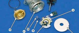
Disassembled distributor for ZMZ
GAZELLE Spare camshaft 4216, 402
- On the transmission we combine the average risk of its shaft on the cylinder head cover, in other words, at the end of the compression stroke of 1 cylinder.
- If the distributor has not been removed from the device, the compression stroke of cylinder 1 can be determined by opening its cover. The slider must be installed opposite the internal contact, which is connected by a cable to the spark plug. If you find that compression has failed, remove the software installed in the first cylinder. Later, the hole should be covered with a cloth, preferably paper. It is necessary to start turning the crankshaft, at the moment when the cardboard plug is pierced by the air flow, the compression stroke will begin.
- Now a 10 wrench is useful - thanks to its use it is necessary to slightly loosen the octane corrector bolt, in this case there is no need to unscrew the screw.
- Then set the scale to zero, which is roughly in the middle of the scale.
- After completing these steps, use a 10-wrench to loosen the bolt that secures the octane adjustment plates.
- Now you need to rotate the distributor body so that the marks are aligned. Namely, we are talking about a reddish mark on the rotor, with the exception of the stator mark. When installation of the drive device is completed, the distributor should be held in one position with one hand, the bolt must be tightened with the other hand.
1. Set tags. 2.4. Set the scale to zero. 3. Align the marks on the distributor.
The gate may be lit. When installed, the ignition does not work - the engine runs three times and does not operate at full power. The reason is the disability of the entire distributor. The problem can be solved by changing, in other words, repairing the distributor.
Preparatory process
Before you begin adjustment work with your own hands, you need to prepare the necessary tools and consumables, which include:
- set of measurement probes;
- a set of wrenches (socket or ring);
- new valve cover gasket;
- crankshaft ratchet key;
- spark plug wrench Needed to remove spark plugs;
- Phillips and flathead screwdrivers;
- clean rags.
Upon completion of preparation, when all the required tools are prepared, you can proceed directly to the adjustment work.
Checking the spark plugs yourself
According to the wiring diagram for engines 405, 406 and 409, spark plugs are used to transfer spark from the switchgear to the engine cylinders. If the operation of the SZ is disrupted, this may affect the quality of the motor as a whole.
To check devices you will need an assistant:
- You need to disconnect the high-voltage wire from the first SZ.
- Using a key, the product is unscrewed from its seat.
- One end of the device from the electrode side should be brought to the engine or metal on the car body, the distance between the electrode and the ground should be about 1-2 mm.
- The assistant then turns the starter to try to start the engine. If at the moment of cranking a spark jumps between the electrode and the body, this indicates that the product is operational. In the same way, you need to check each SZ. Please note that problems with spark supply can also be caused by improper operation of the distributor, as well as damage to high-voltage wires.
Instructions for connecting short circuit
The ZMZ 405, 406 and 409 engines use two short circuits - one of them works with cylinders 1 and 4, and the second with cylinders 2 and 3. The first of them is located closer to the intake manifold, and the second is located next to the exhaust manifold. To make the connection correctly, low voltage wires should be connected in pairs - those used for the first coil (cylinders 1-4) will be shorter in length. Since the short circuits themselves are not polar, it does not matter which contact the cable will be connected to; it also does not play a role within the pair to which cylinder the wire will be connected (the author of the video is the SpawnyXC90 channel).