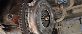
Replacing the emergency stop button on a VAZ
Any owner of a VAZ car has probably encountered problems with the emergency stop button.
The most important of them is the awkward position of the standard emergency tape on the steering gear cover, which is difficult to reach without distracting the eye. This is especially inconvenient and even dangerous when driving.
Often there are problems with the built-in latch, when when the alarm is on it is therefore difficult to turn it off because the button gets stuck. Then you need to completely remove the safety tape and adjust the latch.
All these difficulties can be easily solved with the help of the new euro button, which can be purchased at any online store. After reading this article, replacing the emergency bracelet button will not be difficult even for a beginner.
Overexposure of buttons VAZ/Euro Emergency gang 2113-14.15
To ORDER a kit, you need to write me a letter to https://vk.com/id26998851 or indicating: INDEX, recipient's full name, address. The order will be sent 1st class via Russian Post with 100% prepayment Show in full... ————————————————————— Euro emergency gang kit for VAZ 2113,14,15 and 09,099 with euro panel. The kit is designed to switch from a regular hazard warning button (very inconveniently located on the steering column) of cars: VAZ 2108-2199, with a Euro torpedo and VAZ 2113-2115 cars, to a new type button. ————————————————————-
Signs of malfunction of the mass air flow sensor
Summary of the article:
Precise operation of the engine is impossible without proper operation of all its elements and assemblies separately. One of them is the mass air flow sensor. It measures the air entering the engine cylinders and transmits the data directly to the ECU. This ensures an optimal oxygen/fuel ratio, resulting in maximum engine efficiency.
Why you may need to replace the ignition switch
VAZ 2114 instrument panel pinout
There can be several reasons for this problem, the most common are:
- After all, a broken lock is constantly subject to wear and tear.
- Lost keys.
- Damage due to attempted theft.
- Faulty connector with wires.
The malfunction is easy to determine when the engine is running, if you do not hear the sound of the starter, the relay is triggered, or the electrical equipment simply does not turn on. There are several ways to determine the source of the problem:
- diagnostic;
- visual.
First, you need to check the machine’s reaction to different positions of the key in the lock. First you need to put the key in position number one, also known as the ignition. If the module is OK, the entire electrical system of the vehicle should work. However, if the electrician fails completely or partially, we can conclude that the lock is damaged.
In position number two on the key, the engine starts and the starter engages. If when you turn the key you do not hear the sounds of the starter (turning), as well as the sound of the relay clicking, the ignition switch or the starter itself is broken. In this case, you need to run diagnostics to get more detailed information about the problem.
In this case, you will need a multimeter set to ohmmeter mode. Also, before removing or installing the unit, you must remove the steering column cover.
- + 12V for the microswitch of the inserted key sensor;
- the mass arrives with the driver's door open;
- leaves + 12V to the starter (pin 50);
- + 12V starts after inserting a pin (pin 15);
- + 12V goes out when the key is inserted into pin 5 of the BSK;
- + 12V for lighting the lock cylinder;
- + 12V comes from the battery (pin 30);
- not used.
- The first thing to do is disconnect the ignition switch power connector.
- Then connect the multimeter to the fourth and seventh wires, then do the same with the fifteenth and thirty wires respectively.
- Turn the key in the lock to position number one. If the assembly is not damaged during testing, the multimeter should show zero resistance value.
- Next, you need to turn the key to position number two. The resistance on the multimeter screen, as in the case described above, should be zero.
In a situation where, after checking the lock with a multimeter, the resistance value in at least one of the cases was not zero, it is necessary to replace it. Otherwise, the lock is in good condition and other parts of the vehicle should be checked for damage. To work, you need to prepare spare parts and other accessories.
You will need a new power switch. It is quite easy to find original and analog parts on the Internet, but it is worth considering that it is advisable to purchase a “padlock.”
The number of the original VAZ 2114 ignition switch in the catalog is 21103704010. Estimated price: for a used part 500 rubles, for a new one 1200 rubles.
As a replacement, you can use analogues with numbers: 09401, 24370407. Estimated price: 1000 rubles (new part). In addition to the lock itself, you will need the following tools:
- English keys;
- chisel;
- pliers;
- screwdriver.
Before starting work, you must also remove the steering column cover and steering column switches.
Ignition module VAZ 2114
The ignition module is an important and responsible device in the 2114 ignition system. If it fails or is unstable, the following symptoms will appear:
- unstable idle speed;
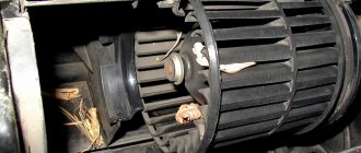
- failures when changing engine speed;
- The second and third or first and fourth cylinders may not work in pairs.
If the first three signs can sometimes be attributed to incorrect ignition installation, then a paired failure of the cylinders only indicates a failure of the coil.
The principle of operation of the ignition module and its tasks are the same as those of the ignition coil, only the module also distributes high voltage current between the cylinders. It supplies sparks in pairs to 1/4 and 2/3 cylinders. In more finely organized ignition systems, each cylinder has its own coil, but the 2114 module is also capable of providing a spark to the cylinders in the order of their operation - 1-3-4-2
When working with the ignition module, it is important not to mix up the wires. The required cylinder is marked on the module body, so if you are careful, an error is excluded. The ignition module cannot be restored, so it must be checked for functionality especially carefully.
If the device shows signs of incorrect operation, the computer displays the corresponding error codes: P0351 indicates that the coil of the first and fourth cylinders is not working, and P0352 indicates that the coil of the remaining two cylinders is not working. You can also check the resistance of the coils for insurance. If they are working, then at the input of paired cylinders (1-4 or 3-2) the ohmmeter will show 5.4 kOhm. Otherwise, the module has served its purpose. A new device costs about 1000 rubles
The ignition module cannot be restored, so it must be checked for functionality especially carefully. If the device shows signs of incorrect operation, the computer displays the corresponding error codes: P0351 indicates that the coil of the first and fourth cylinders is not working, and P0352 indicates that the coil of the remaining two cylinders is not working. You can also check the resistance of the coils for insurance. If they are working, then at the input of paired cylinders (1-4 or 3-2) the ohmmeter will show 5.4 kOhm. Otherwise, the module has served its purpose. A new device costs about 1000 rubles.
We touched only on a few faults in the VAZ 2114 electrical wiring system. The rest will be helped by the diagram above and intuition, without which any repair is impossible. Good luck on the roads!
How to remove and connect the euro hazard warning button on a VAZ
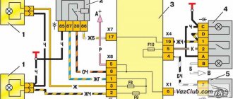
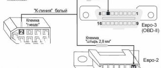
Before you begin installing the emergency bandage, you should familiarize yourself with the connection diagram for the Euro button on the VAZ-2114 (2115), which we will use as an example.
This circuit avoids the use of relays and interference with standard wiring.
- I connected the contacts of the old connector “1” and “3” to terminal “2” of the emergency button;
- Output “2” to the button - to output “D”;
- Contact “7” - for contact “1” on the button”;
- Conclusion “B” - to the backlight;
- Conclusions “A” and “C” are massive;
- Terminals “8” and “4” in the old terminal block are connected by a jumper.
To replace the emergency button we need the following:
- Euro button with padlock underneath;
- Two 1N4007 diodes;
- Welder;
- LTI-120 flow;
- Screwdriver;
- Two terminals.
Having prepared all the necessary tools, we proceed to replacing the old emergency bandage using the example of a VAZ-2114 (2115) car and alarm switch 2515 996.3710-07.10 according to the diagram above.
First you need to disassemble the emergency button in the following sequence:
- Using a screwdriver, remove the steering cover;
- We remove the chip from the old switch and the switch itself from the housing;
- Unscrew the two screws and remove the side panel on the driver's side;
- We take out the released microcircuit into the window where the on-board computer is usually located;
- We disassemble the old emergency button using a flat screwdriver - there are two recesses; by prying it off, it can be divided into two parts;
- We keep the lock of the old emergency tape connector for ourselves; the spring can be pushed out - we won’t need it anymore.
- Then we proceed to connecting new contacts and the switch:
- To obtain a reliable seam, the contact surfaces must first be tinned with LTI-120 acid;
- Contacts “4” and “8” of the microcircuits are immediately connected to each other using wiring;
- On the same microcircuit, on contacts “1” and “3” we solder two diodes with cathodes and connect the anodes to each other;
- The wires of the new switch from contacts “2” and “D” are soldered to the free anodes of the diodes;
- In order for the triangular hazard warning sign to flash, the wire of contact “2”, designated in the diagram as “to order”, is brought to the instrument panel and connected to a free contact (do not forget to insert the lamp bulb along the ordinate axis, since it is not supplied by the factory );
- Solder the wire from contact “1” of the emergency button to contact “7” on the microcircuit;
- The remaining contacts of the connected switch “A” and “B” go to ground and backlight, respectively. Take two wiring terminals and solder them to pins "A" and "B". If necessary, this will allow you to remove all new cables without affecting the old wiring;
- We connect the new harness to the wiring and connect the free ends of contacts “A” and “B”, to which the terminals were soldered, to the microcircuit hanging freely on the fog lights.
Connect the ground and backlight, insert the button. All is ready!
Note that jumpers "4" and "8" in the old hazard switch terminal block allow the hazard kit to be used even when the ignition is off.
This is the only side effect of such a connection, but it is insignificant, because no one forces the alarm to go off when the ignition is turned off.
In this case, there is no need to use a relay, and, as mentioned above, the button can be painlessly removed for factory wiring at any time.
Even a person who is far from such connection diagrams can independently replace the alarm button on a VAZ. Financial costs are minimal, the procedure time is a maximum of 30 minutes. The end result is that your vehicle will have a modern hazard light located in a convenient location.
Recommendations
Comments 50
Algorithm for replacing the main brake cylinder on a VAZ 2114
The other day I installed the same button from VAV-21123. I didn't connect the indicator. The wiring marked “Dimensions” is also not connected anywhere, but the emergency lights are working (all turn signals and repeaters are blinking, the arrows on the dash are blinking, the light in the button is blinking, there is a clicking sound). What is this wiring for (“Dimensions”)?
Then some miracles began. The day before yesterday the following happened several times: arbitrary single clattering of the turn signal while driving (the sound was heard, but I did not notice whether the turn indicator (arrow) was blinking), as well as some kind of grinding noise (as if it was shorting) after turning off the turn signal (had to several times pull the handle back and forth to make it disappear). This happened several times.
Yesterday all this no longer happened, but on one of the turns the car simply passed out - it stalled, but continued to roll. Turned the ignition off and on - it started and drove on. Today this happened again while overtaking, blinking in the other direction. It feels like it was switched off when the turn signal was turned on.
Read more: Indicator for determining TDC
Whether all these events are related to the installation of a new button, or whether it was a coincidence, I don’t know, but it’s disturbing in any case.
>> What is this posting (“Dimensions”) for? In order for the button illumination indicator to glow green when the side lights are turned on)) Most likely a coincidence (I’m talking about a stalled engine). But what is clicking... maybe something is wrong with the relay or the power supply to pin 13 of the relay.
Since then there haven’t been any more such quirks - apparently the button has caught on
Materials
1. Electrical tape (preferably blue, as it is especially strong) 2. Four-pin relay for direction indicators from VAZ 2106 3. Relay socket 4. Six-pin alarm on/off button 5. Socket for the button 6 Cable for installing and connecting the above. Tools: 1. Pliers with wire cutters 2. Flat-head screwdrivers 3. Phillips screwdrivers 4. 10mm wrench 5. Knife For those who want to save money due to manufacturability: you can also use your own relay from the VAZ 2101, but in this case adequate operation is not guaranteed, so as this relay is very sensitive to load fluctuations. For this reason, the next installation method is to replace the relay with a more modern one. Let's get started, unscrew the nut securing the turn signal relay and disconnect the three multi-colored wires from it. Next, we determine where to install the panic button. Here we give freedom to our imagination, but a lot also depends on what kind of panel is installed in your car. To the second contact of the relay we connect the wire removed from the contact of the old relay, marked with the letter “L”, and connect it all to the seventh contact of the panic button. We connect the first contact of the emergency relay to the fourth contact of the button. We connect the third contact of the relay to the wire extended by contact “P” of the old relay. We connect the wire from the fourth contact of the relay to the body. The best solution would be to secure the wire under the nut of our relay.
Diagram of the emergency (signal) range for the VAZ 2101 car
Now tighten the relay mounting nut with moderate force so as not to break the plastic holder. Then we connect the second contact of the button to the positive wire of the old relay. The first and third contacts of the button are connected to the turn signal switches on the steering column in any order. The eighth contact of the button is connected to a constant “plus” (regardless of the position of the key in the ignition switch). It is recommended to protect this circuit with a fuse. The most suitable would be to install a fuse rated 8A. Next, you should wrap the wires with electrical tape and secure them so that they do not hang down, install all previously removed casings and panels. Now we have a full-fledged alarm system, and we can heal a new full-fledged life. The entire procedure for installing an alarm on a VAZ 2101 takes 2-3 hours.
Euro emergency gang 2114 do it yourself
Download Raid: Shadow Legends for free ✅ Mobile: .
16 funny college pranks and life hacks
Subscribe to the channel: .
RAUF & FAIK – LULLABY (PARODY)
Best prices here: https://ek.ua/u/itdWY Bonus 2500 UAH in .
Blitz-scream #7: Smetana TV (Evgeny Kalinkin, Vasily Shakulin), Olga Parfenyuk
Learn English with skyeng https://skyeng.ru/go/blickrik.
My damn scooter (Animation)
Save THANK YOU bonuses and give the right gifts: .
Lyubov Sobol: about the assassination attempt on her husband, divorce, daughter, hunger strike and favorite cherry beer // Let’s talk
Get a discount of 1000 ₽ on Grow Food: https://clck.ru/MCCk9 Order.
MORGENSHTERN and SLAVA MARLOW: about Legendary Dust, Evening Urgant and RATATATATA with Vitya AK
Guess the promo code and get a free 45-day subscription to .
VLOG My sister was NOT INVITED to the wedding! Let's celebrate February 23rd! Mom gives GIFTS!
VLOG My sister was NOT INVITED to the wedding! Let's celebrate February 23rd! Mother .
WALRUCK SHOW - FALLED UNDER THE ICE // WITH A HAMMER UNDER THE ICE
MY INSTA - https://instagram.com/maevamasha And my tik tok❤️ .
MORGENSHTERN & Vitya AK - RATATATA (Clip Premiere, 2020)
LISTEN EVERYWHERE: https://band.link/mrgsht_lp THE BEST CONCERT EVER.
Zaharli tomchilar (o'zbek serial) | Zakharli Tomchilar (Uzbek TV series) 119-qism
“Zaharli Tomchilar” (Uzbek TV series) Davomiyligi: 30 dakika Ishlab.
The first crossover in the world: AMC Eagle (test and history)
Large article about AMC in Avto.ru Magazine: https://clck.ru/MH7F3.
12 lifehacks for drawing
Subscribe to the channel: .
Iztirob (O'zbek serial) I Iztirob (O'zbek serial) 133- Qism 2-Fasl
Iztirob (Özbek series) 2-Fasl Davomiyligi: 30 dakika Ishlab.
THE ROOTS OF TARASOV HAVE BEEN BROUGHT OFF! / ATTACKED HIS BROTHER AND COACH
TARASOVMMA - PROMO CODE (BONUS UP TO 6500 RUBLES) Introducing the new .
FOR THE FIRST TIME I ORDERED SURPRISE BOXES WITH OZON FOR 20,000 RUBLES! DIVORCE?!
SUBSCRIBE TO THE CHANNEL ▶ https://www.youtube.com/channel/UCL4J. .
PROBLEMS OF SHORT AND TALL PEOPLE || Such familiar awkward situations!
Awkward situations that short and tall people find themselves in.
5 LIFE HACKS FROM SLIVKISHOW
Instagram collaboration - .
Happy Box From Rakhim Abramov! RUR 3999 For a small box! Real price Surprise boxing.
Xiaomi Air 2 choose price and store on the E catalogue: .
Jesus - The radiance of the sky is not visible to the eyes
THE BEGINNING OF A NEW ERA TOUR 2022 - https://dzhizustour.com/ Director: .
Relays and fuses VAZ 2114
- F1 for rear fog lights 10 Amp (A) and rear fog light indicator lamp.
- F2 10 A direction indicators, direction relay, hazard warning group, hazard warning light.
- F3 7.5 A Lampshades for interior lights (both) and trunk, ignition lights, transmission control warning light, brake lights, computer, if equipped.
- F4 20 A support, rear window relay and resistor.
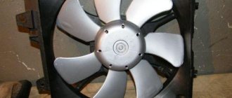
- F5 20 A horn and corresponding relay, cooling fan.
- F6 30 A power windows and relative relays
- Electric heater motor F7 30 A, headlight washer, windshield washer, cigarette lighter, glove box light, winding relay for turning on the rear window heating.
- F8 7.5 There is fog on the right.
- F9 7.5 Left fog lamp.
- F10 7.5 Left side, lamp signaling the inclusion of side lights, lamp for illuminating the sign, engine compartment, switch and instrument lighting, instrument lighting switch.
- F11 7.5 A right side.
- F12 7.5 A low beam right.
- F13 7.5 A low beam on the left.
- F14 7.5 Left high beam and a lamp indicating that the high beam is on.
- F15 7.5 A on the far right.
- F16 30 A - warning light indicating insufficient oil pressure, brake fluid level, parking brake, low battery, instrument cluster, lamp control relay, control system indication, reversing lights, direction indicators and related relays, and alarm system, if the turning mode is turned on, the ECU, the generator excitation winding when starting the engine.
General information about turn signals
If you read the history of the car, this part was not originally included in the kit, and drivers installed it additionally for a fee. In modern cars, turn signals are often located on or near the headlight, whichever comes first. The rear turn signal is installed near the headlight. Repeaters of this necessary part can be placed on the wings and on the mirrors. There is a technology for duplicating mirrors using diode lamps. Now this is considered the most progressive.
The direction indicator consists of the following parts:
- mechanical drive (for starting and stopping);
- switch (for connecting lamps to a power source);
- relay to close and open the circuit after a certain time.
Some cars have a very good functional solution - a triple flasher with a quick press, drivers really like this quality.
If not, you can install a device that increases the number of signals.
When the turn signal is turned on, a characteristic sound is heard. In modern cars it can be changed to a more pleasant one. This part of the car gives off a bright yellow glow, sometimes mixed with orange. On American models they are sometimes red, which leads to an increase in traffic accidents because they are confused with stop signs.
Traditionally, they are turned on as a malfunction indicator - “emergency mode”. The turn signal is a kind of language for drivers to communicate on the road. Overtaking and other circumstances may become undesirable.
Turning your turn signals on in a timely manner is an indicator of your ability to drive and control the situation on the road.
Electrical diagram of VAZ 2114
Main electrical equipment of VAZ 2114:
Generator
The machine is equipped with a 3-phase alternating current generator with a voltage regulator and a rectifier unit (a device that converts direct current into alternating current).
Consists of the following elements:
- Covers with special holes for bearings;
- Brushes, which are a kind of non-separable unit;
- Winding;
- The core cylinder into which the winding is placed;
- Diode blocks (6 power and 3 additional);
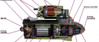
Starter
This is a motor powered by electricity. It contains 4 magnets that provide excitation of the device.
Its main malfunctions are: the armature does not rotate or has a low rotation speed, the relay does not work or is activated repeatedly and turns off, the flywheel does not rotate, and an unusual noise is heard when the armature rotates.
Electrics of doors and interior
Part of the electrical equipment of the fourteenth model, like any other car, is located in the doors. The electrical circuit of the VAZ 2114 includes door electrics and is represented by the following elements:
Seat heating;
This is an additional option and is not included in all car configurations.
Electric windows;
This option is also not present in the standard (blank) model.
Locking of locks;
Car electrical equipment
1 — lighthouse block; 2 — gear motors for headlight washer*; 3 — fog lights*; 4 - room temperature sensor; 5 — sound signals; 6 — engine compartment lamp switch; 7 — electric motor of the cooling system fan; 8 — VAZ 2114 generator; 9 — low oil level indicator sensor; 10 — washer fluid level sensor; 11 — front brake pad wear sensor; 12 — cable lugs connected to the common windshield washer pump**; 13 — windshield washer pump; 14 — headlight washer pump*; 15 — end of the cable for connecting to the rear washer pump on VAZ 2113 and VAZ 2114 cars; 16 — low oil pressure indicator sensor; 17 — engine compartment lighting lamp; 18 — wire tip for connection to the engine control system harness or to the ignition system harness on carburetor vehicles; 19 — electric motor of the windshield wiper; 20 — VAZ-2114 starter device; 22 — coolant temperature indicator sensor; 23 — reversing light switch; 24 — sensor for insufficient brake fluid level indicator; 25 - battery; 26 — sensor for insufficient refrigerant level indicator; 27 — relay for turning on fog lights; 28 — mounting block; 29 — brake light switch; 30 — socket for a portable lamp; 31 — illumination lamp for the beacon’s hydrocorrecting scale; 32 — parking brake warning lamp switch; 33 — block for connecting the backlight; 34 — switch for instrument lighting lamps; 35 — switch on the steering column; 36 — alarm switch; 37 — front seat heating element relay; 38 — ignition switch VAZ 2114; 39 — rear fog lamp circuit fuse; 40 — front seat heating element fuse; 41 - locking circuit fuse; 42 — front ashtray lighting lamp; 43 — ignition relay VAZ-2114; 44 — cigarette lighter; 45 — glove box lighting lamp; 46 — glove compartment lighting switch; 47 — heater fan electric motor; 48 — additional resistance of the heater electric motor; 49 — heater fan switch; 50 — heater switch backlight; 51 — lamp for illuminating the heater levers; 52 — Gear motors for electric windows of the front doors; 53 — right front door power window switch (located in the right door); 54 — gear motors for front door locks; 55 — cables for connecting to the front right speaker; 56 — gear motors for locking the rear doors; 57 — cables for connecting to the rear right speaker; 58 — control unit for locking doors; 59 — cables for connecting to radio equipment; 60 — wiper switch; 61 — rear window resistance switch; 62 — relay for turning on rear fog lights; 63 — connection block to the resistance of the right front seat; 64 — rear fog light switch: 65 — right front seat heating element switch; 66 — fog lamp switch; 67 — switch for external lighting lamps; 68 — left front seat heating element switch; 69 — connection block to the resistance of the left front seat; 70 — cables for connecting to the front left speaker; 71 — left front door power window switch; 72 — right front door power window switch; 73 — cables for connecting to the rear left speaker; 74 — side direction indicators: 75 — light switch on the shelves of the front doors; 76 — light switch on the rear luggage racks; 77 - ceiling; 78 - ceiling of individual internal lighting; 79 — block for connecting to the wiring of the electric fuel pump VAZ 2114; 80 — trunk light switch; 81 — instrument panel: 82 — trunk lighting lamp; 83 — display unit of the on-board monitoring system; 84 — on-board computer (not in all models); 85 — block for connecting the wiring of the engine control system; 86 — external rear lights of the VAZ-2114; 87 — interior rear lights; 88 — connection block to the rear window heating element; 89 — license plate illumination; 90 - additional brake signal located in the spoiler.
In the instrument panel wiring, the second ends of the white wires are brought together into one point, which is connected to the instrument lighting switch (except for the white wire from plug “4” of the “X2” block of the mounting block 28 of the display unit. 83 of the on-board monitoring system). The other ends of the black wires are also connected at the grounding points. The second ends of the yellow wires with the blue stripe are connected at a point connected to the "4" plug of the "X1" mounting block. The second ends of the white wires with a red stripe are connected at the connection point to the “10” plug of the “X4” mounting block. And also the second ends of the orange wires are connected at the point connected to plug “3” of the “X4” block.
General recommendations
When the first signs of a malfunction of the turn signal system appear, it is necessary to take measures to eliminate them immediately.
Always store your turn signals and indicators in a repair kit.
Periodically pay attention to the turn signals on the instrument panel while driving.
If the key in the ignition switch does not turn, what should you do in this case?
Which car radio antenna is better to choose when using in a metropolis, and which one when traveling long distances.
Emergency warning button VAZ 2114: review and replacement options
The standard emergency clamp of the VAZ 2114 installed at the factory causes outrage among many car enthusiasts. The reason here lies in the fact that it is not installed in its usual place - on the panel, but on the side on the steering column trim.
This arrangement makes it much more difficult to quickly use the button while driving (for example, to say “thank you,” which is common for most drivers). It is for this reason that many are considering moving him.
It’s worth noting right away that the VAZ 2114 emergency strap button has non-standard dimensions, as a result of which it will not be possible to simply move it from the steering column to the Europanel - it simply won’t fit. And on the body itself, instead of the previous location of the button, there will be a large hole.
It is for this reason that replacement should be made in this order:
- dismantling the original emergency bandage;
- disassembling the column casing;
- installation of a new casing;
- connect the new euro button to the network;
- fastening the button on the panel.
Lada 2114 SnowMan › Logbook › Relocating the emergency gang
The reason for moving the panic button (hereinafter referred to as CAS) is due to two factors: 1) CAS, in my opinion, is located in a very inconvenient place. 2) The plans include installing a Kalina steering wheel and covers. Since there was no free space on my panel (there was only 1 plug left for the front PTF) for CORRECT CAS, I decided to install it instead of the cigarette lighter. I was very happy that the CAS cables were long enough for such a transmission and did not have to be increased. The appearance of the button itself, which looks more like a save button, didn’t really inspire me, so I decided to find an alternative to the stock button. That's what I liked.
— Alarm switch — 1 piece (110 rubles)
Since the place of the cigarette lighter was taken by CAS, and I often use it to charge my phone, I decided to install it to the right of the ashtray. To do this, it was necessary to drill a hole with a diameter of 29 mm. There was no drill of the required diameter, and I didn’t think cutting a hole with a round file was the best option. Having thought about what else you can do, you can make a hole with a large diameter, using circular type drills (crowns). The set includes a crown in the size I need.
Having made a hole, I processed the edges with a file and installed the cigarette lighter. The wire from the cigarette lighter was also enough, I didn’t save it.
Here's what I did.
Two positive points: 1) Now it has become more convenient to thank polite drivers (there is no chance of breaking your arm). 2) Charging a phone connected to the cigarette lighter no longer interferes with changing gears.
Since there was now a HUGE hole in the steering column housing due to the lack of UAS, it was necessary to drown it with something. Information has appeared on the Internet that a window regulator plug is suitable as a plug for this hole. I couldn’t find such a plug at the nearest auto store, but my eye fell on a rubber floor plug (it seemed to be the right size) that I bought.
— Floor plug 2108-5112090 large — 1 piece (16 RUR)
The cover with plug is installed (fits perfectly).
Euro emergency gang 2114 do it yourself
Download Raid: Shadow Legends for free ✅ Mobile: .
16 funny college pranks and life hacks
Subscribe to the channel: .
RAUF & FAIK – LULLABY (PARODY)
Best prices here: https://ek.ua/u/itdWY Bonus 2500 UAH in .
Blitz-scream #7: Smetana TV (Evgeny Kalinkin, Vasily Shakulin), Olga Parfenyuk
Learn English with skyeng https://skyeng.ru/go/blickrik.
My damn scooter (Animation)
Save THANK YOU bonuses and give the right gifts: .
Lyubov Sobol: about the assassination attempt on her husband, divorce, daughter, hunger strike and favorite cherry beer // Let’s talk
Get a discount of 1000 ₽ on Grow Food: https://clck.ru/MCCk9 Order.
MORGENSHTERN and SLAVA MARLOW: about Legendary Dust, Evening Urgant and RATATATATA with Vitya AK
Guess the promo code and get a free 45-day subscription to .
VLOG My sister was NOT INVITED to the wedding! Let's celebrate February 23rd! Mom gives GIFTS!
VLOG My sister was NOT INVITED to the wedding! Let's celebrate February 23rd! Mother .
WALRUCK SHOW - FALLED UNDER THE ICE // WITH A HAMMER UNDER THE ICE
MY INSTA - https://instagram.com/maevamasha And my tik tok❤️ .
MORGENSHTERN & Vitya AK - RATATATA (Clip Premiere, 2020)
LISTEN EVERYWHERE: https://band.link/mrgsht_lp THE BEST CONCERT EVER.
Zaharli tomchilar (o'zbek serial) | Zakharli Tomchilar (Uzbek TV series) 119-qism
“Zaharli Tomchilar” (Uzbek TV series) Davomiyligi: 30 dakika Ishlab.
The first crossover in the world: AMC Eagle (test and history)
Large article about AMC in Avto.ru Magazine: https://clck.ru/MH7F3.
12 lifehacks for drawing
Subscribe to the channel: .
Iztirob (O'zbek serial) I Iztirob (O'zbek serial) 133- Qism 2-Fasl
Iztirob (Özbek series) 2-Fasl Davomiyligi: 30 dakika Ishlab.
THE ROOTS OF TARASOV HAVE BEEN BROUGHT OFF! / ATTACKED HIS BROTHER AND COACH
TARASOVMMA - PROMO CODE (BONUS UP TO 6500 RUBLES) Introducing the new .
FOR THE FIRST TIME I ORDERED SURPRISE BOXES WITH OZON FOR 20,000 RUBLES! DIVORCE?!
SUBSCRIBE TO THE CHANNEL ▶ https://www.youtube.com/channel/UCL4J. .
PROBLEMS OF SHORT AND TALL PEOPLE || Such familiar awkward situations!
Awkward situations that short and tall people find themselves in.
5 LIFE HACKS FROM SLIVKISHOW
Instagram collaboration - .
Happy Box From Rakhim Abramov! RUR 3999 For a small box! Real price Surprise boxing.
Xiaomi Air 2 choose price and store on the E catalogue: .
Jesus - The radiance of the sky is not visible to the eyes
THE BEGINNING OF A NEW ERA TOUR 2022 - https://dzhizustour.com/ Director: .
14 PIECES FROM ONE HOLE THIS FISHING HAPPENS ONLY ONCE fishing in winter 2020
fishing in winter 2022 catching pike perch in winter my VK group.
How to install the euro button?
To install a Euro-sample button instead of the factory installed one, you will need to purchase the following electronic components:
- Euro button for emergency lights VAZ 2114.
- Block for its installation.
- Relay type HLS4453.
- Block for the specified relay (it is possible without it, but blocking greatly simplifies assembly).
- Approximately 2 meters of wire with a cross section of about 0.5 square meters. Mm.
- Terminals in the amount of 6 pcs.
- Insulating tape.
The first thing to do is connect the new Euro button to the electronic relay.
This should be done according to the following scheme:
All wires going from the new button to the relay must be securely fastened (preferably soldered). And the terminals should be connected to the ends of the wires coming from the relay to the old button (or rather, to its block.
Despite the fact that the connection using terminals is quite strong, it is still recommended to solder it by applying a small amount of solder to the wire entry point - this will significantly increase reliability and improve contact.
After connecting the Euro 2114 emergency tape and relay, you will need to remove the old button. To do this, first unplug it from the socket and then disconnect it from the electronic lock. The block itself needs to be moved to the europanel (where the new button should be attached), then 6 terminals from the relay must be connected to it. This must be done according to the numbering of the wires coming out of the relay, which was shown in the diagram above.
On the block itself, if you place it with the empty slots down, the numbering will look like this (clockwise): 4-3-2-1-8-7.
Then we disconnect the side light button from its block and connect to it the wires coming directly from the button (indicated in the diagram). One goes to the size wire (it's white), the other goes to the negative wire (it's completely black). All connections must be well twisted and insulated. Next, we connect the size button to the block.
The last thing left to do before the Euro-crash on the VAZ 2114 is finally installed in its place is to remove one (any) plug on the Euro-panel, bring the lock connected to the system to it, and simply insert the button into it.
If your car has an on-board computer, it must be turned off before installing a new alarm button. There is no need to turn off other electronic devices.
Improvement of the emergency button
Volkswagen Passat Variant Red line Logbook Electric trunk
Every driver uses the hazard warning lights quite often, the reason for this is the established rules of behavior on the road. When a car is allowed to pass in a traffic jam, according to unwritten laws, as a sign of gratitude you need to flash your emergency lights. On some modern cars, the manufacturer installs special “thank you-sorry” buttons, which turn off automatically after a few blinks. If there is no such button, then you have to read the signals yourself and interrupt them manually. The situation can be corrected with a small improvement.
Changing the operating principle of the alarm when installing the device
If you briefly press the emergency button, the mechanism will give a quick signal with a beeper and roll back to the last program installed by a specialist (the light is on continuously in this mode). Two presses switch to the normal alarm mode. The warning lights will flash until the driver presses the button to cancel.
After pressing and releasing the button, the device passes three beeper signals, after which it writes the next program into memory, works on it and goes into standby mode. The beeper is programmed to automatically turn off after the fourth blink of the light.
When switching from one operating mode to another, two lines of conductors are turned on (also relevant for the beeper at rest). The operating status of the device is monitored by the conductor indicator lamps on the vehicle’s instrument panel.
Operating procedure
The basis of the device is an inexpensive microcontroller (Microchip PIC 12 A 629). The brand was chosen taking into account the stock of flash memory and unused cells.
When the necessary device base is prepared, you can proceed directly to the creation of the following elements. At the first stage of work, we remove the fixation and remove the chip.
Next, you need to remove the light bulb and, carefully unhooking the clippers, remove the top cover.
After removing the moving part of the button, a metal pin is removed, which ensures its fixation. Then assembly is carried out in the reverse order.
The next step is to prepare the button itself. To do this, the wires are removed and their ends are insulated with heat shrink tubing.
The red wire must be connected to the “plus”, to a specific pin. One of the black wires will be responsible for ground, and the second will be responsible for recognition. The yellow wire should go to the light bulb.
Next you need to install the finished button in the car.
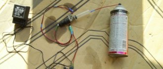
At the final stage of the work, attach the buzzer to the wiring harness using a thermal pestle or a simple clamp. The short ends must be soldered according to the diagram to the microboard, and the long ends must be attached to the car chip. It is recommended to install wires in a twisted manner.
The operating principle of the finished device that controls the alarm button is shown in the video.
In the attached ARCHIVE-1 and ARCHIVE-2 you can find the source materials and diagrams for manufacturing the device.
Scheme for switching on headlights, side lights and turn signals for VAZ-2113, 2114 and 2115
Headlight switching diagram for VAZ-2113, 2114 and 2115
Ignition circuit for headlights and fog lights:
1 — block headlights; 2 — mounting block; 3 — headlight switch; 4 — ignition switch; 5 — external lighting switch (fragment); 6 — fog lights in the rear interior lights; 7 — fog light switch with warning lamp; 8 — indicator lamp for high beam headlights in the instrument cluster; K8 - high beam relay; K9 - relay for low beam headlights; A - the order of conditional numbering of plugs in the headlight block; B - to power supplies
Scheme for switching on the side lights of VAZ-2113, 2114 and 2115
Scheme for switching on external lighting:
1 — side lights in the headlights; 2 — engine compartment lamp; 3 — mounting block; 4 — engine compartment lighting switch; 5 — ignition switch; 6 — external lighting switch (fragment); 7 — indicator lamp for external lighting in the instrument panel; 8 — side lights and brake lights in the external rear lights; 9 — license plate illumination; 10 — instrument lighting regulator; 11 — brake light switch; 12 — blocking of the on-board control system; K4 - lamp status monitoring relay (contact jumpers are shown inside the relay, which should be installed if there is no relay); A - to power supplies;
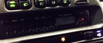
Designations of light bulbs, indicators, icons and buttons on the instrument panel of VAZ 2114, 2115
Connecting an alarm system to the central locking on a VAZ 2114
First, let's look at the descriptions and meaning of the panel icons and buttons, regardless of whether the car is equipped with an injector or a carburetor.
Instrument panel diagram VAZ 2114, 2115
1 - Control sensor that measures the temperature of the coolant in the engine cooling system. During normal operation of the power unit, the antifreeze temperature should not exceed 90 degrees. But minimal deviations are sometimes acceptable. If you notice that the engine begins to overheat frequently, be sure to contact a car service center for help. Sometimes the sensor itself may give incorrect results.
2 - A device such as a tachometer processes information that comes from the crankshaft and displays it on the panel. The tachometer readings indicate the number of engine revolutions.
3.4 - Turn indicators. If the indicators flash simultaneously, but slowly, this may indicate a possible problem with the bulbs themselves or in the electrical wiring network.
5 — The most basic element of any instrument panel is the speedometer. Thanks to it, the driver can determine the speed of movement. A slight error in the indicators is allowed, but it should not exceed the indicator by more than 5 kilometers. If such readings differ significantly from the real ones, then most likely the problem is in the speedometer.
6 — Fuel level sensor in the fuel tank. When the level in the tank drops to 6-7 liters, a red light comes on, indicating that the car needs to be refueled.
7 - Low fuel level indicator.
8 — Symbol indicating the light is turned on. It is triggered when the low beam and parking lights are turned on.
9 — The brake light indicates that the vehicle’s brake system is not working correctly. Most often it lights up if there is not enough brake fluid in the car.
10 - A blue light indicates that the high beam headlights are on.
11 — Button for resetting the daily mileage. The total mileage of the car is shown at the top, and the daily mileage at the bottom.
12 - on-board computer display with mileage indicators.
13 — Alarm activation symbol (light). When the emergency light is turned on, the light begins to flash red.
14 — “Check” symbol. It is triggered in case of possible problems with the car’s power unit. There can be many reasons for this, from problems with mixing the combustible mixture with air, to breakdowns of various engine power components. In any case, you need to contact the service for computer diagnostics or repairs.
15 — External air temperature sensor and time indicators. The daily mileage reset button allows you to scroll from the temperature readings to the time readings when scrolling.
16 - Battery charge sensor. Most often it lights up when the battery is almost completely discharged. If the indicator light is very weak or, on the contrary, bright, then the problem may be in the generator.
17 - Handbrake activation icon. It lights up both when the engine is on and vice versa.
18 — Icon showing engine fluid pressure. Usually its appearance indicates an insufficient amount of lubricating mixture. In such a case, be sure to check the oil level. Sometimes the problem can be caused by the oil pump not working properly.
19 - If the engine is equipped with an injector, then there is a reserve icon on the dashboard. Well, if the engine is carburetor, then this is a suction indicator.
Buttons on the instrument panel
- Dimensions switch
- dipped headlights
- Front fog light button
- Rear fog lights
- Heated rear window
Replacing the column casing
As already mentioned, when removing the old button from the steering column cover, a large hole remains in the latter. Of course, this will not interfere with the operation of the machine, but it is still better to replace the casing.
When choosing a new one (and you will have to take it from other VAZ models), you should consider the following points:
- presence of all necessary holes for control elements;
- their location;
- the size of the hole for the steering wheel (for example, on the casing for Kalina is very large).
The optimal one, according to reviews from car enthusiasts themselves, is a standard (not “euro”!) casing for the tenth model.
When do the hazard warning lights turn on?
Its use is mandatory in the following situations:
- if a traffic accident occurs;
- if you had to make a forced stop in a prohibited place, for example, due to a technical malfunction of your car;
- when in the dark you are blinded by a car coming towards you;
- Hazard lights also turn on when the vehicle is being towed;
- when boarding and disembarking a group of children from a specialized vehicle, it must be accompanied by an information sign - “Transportation of children.”
How does the alarm circuit work?
Due to the large number of connecting wires, the modern alarm circuit has become significantly more complicated compared to its prototype, and consists of the following: the entire system is powered only from the battery, so it can ensure its full operation even if the ignition is turned off, i.e. while the vehicle is parked. At this time, all the necessary lamps are connected through the contacts of the alarm switch.
When the alarm is on, the power circuit operates as follows: voltage is supplied from the battery to the contacts of the mounting block, then it is supplied directly to the alarm switch through a fuse. The latter connects to the block when the button is pressed. Then it, again passing through the mounting block, goes to the turn signal relay.
The load circuit has the following diagram: the alarm relay is connected to contacts, which, when the button is pressed, come into a closed position with each other, thus they connect absolutely all the necessary lamps. At this time, the warning lamp is switched on in parallel through the contacts of the hazard warning switch. The connection diagram for the alarm button is quite simple, and it will take you no more than half an hour to master. It is necessary to remember its importance, so be sure to monitor its condition.
Euro emergency warning button VAZ 2115
In the end, I decided to make a hazard button (or, more simply put, a "hazard strip") myself. In our Russian VAZ 2113-2115 it sits well in a very uncomfortable place. More precisely behind the wheel. And in the modern rhythm of life, when it has become customary to “blink” at the emergency lane as a sign of greeting or gratitude, such an arrangement is unacceptable.
I started by ordering “Relay HLS-4453 (18F) -4, DC12V, 4 groups of contacts. 5A "from the site www.ekits.ru/index.php?product >
Then I bought 1.5 wires, many wrote that these are the only ones needed, but they are too large and 0.75 above the roof is enough. Bought, as in common parlance, “PPA” and electrical tape. So, a soldering iron in your hands and a diagram in front of your eyes.
Everything is quite simple, but you waste a lot of time, if you assemble it for the first time, then I assembled it from scratch in 3 hours)) Then INSTALLATION: I forgot to take most of the photos myself, so I took this from other users: www.drive2.ru/l/363984 / and www.drive2.ru / l / 1042092/
We disassemble the instrument panel and remove the casing.
We remove the casing and disassemble the old emergency tape button and move the wires to a place convenient for us.
We begin to slowly collect our miracle. We place the button where it will be most convenient for us to use it.
We assemble the wires from the new button to the old one according to the diagram.
Just in case, I tied it with electrical tape so that it would not fly out of the connectors on uneven surfaces. Then install the DIN rail into the empty space. And tighten it with nut and bolt 5.
We install the block with the relay on it.
And finally, let's start connecting to the dimensions and the dashboard itself.
I draw your attention to the fact that according to the diagram there are two drawbacks, they can be combined into one, but I made them 2 different and connected them to the size block, there are 2 black wires, both are drawbacks, I did both)) And the size The new one connected the buttons to the white wire on the block.
Next, let's move on to the toolbar itself. We unscrew it, it is secured with two self-tapping screws. At the back we see two contact pads, white and red, we need the red one and connect the wire there, which we go according to the diagram into an empty socket.
This is so that the red triangle lights up (you can do without it). Looks really cool. PS Some panels do not have a triangular backlight, you need to buy one and screw it on.
In the end, this is what my button looks like
It took me about 2 hours to install.
All you need for the euro button:
1. Relay HLS-4453 (18F) -4, DC12V, 4 groups of contacts. 5A — 106 rub. 2. Relay block HLS-4453 (18F) - 62 rubles. 3. Euro button - 91 rub. 4. Lock on the euro button - 50 rubles. 5. DIN rail - 7 rubles. 6. Dad - 7 pieces - 40 rub. (we buy 6 large and 1 small). 7. Wires 1.5 - 7 meters * 8.2 rub. = 58 rub. (I repeat, it’s better to take 0.75 threads and 7 meters was not enough for me, take 8 meters). 8. Electrical tape - 15 rubles.