AutoNews / Reviews / Tests
How to set the ignition on a VAZ 21213
Adjusting the electric ignition of a VAZ 2106 - YouTube
It must be said “how to set the ignition on a VAZ 2106” is a fairly common question. Installing the ignition on the VAZ 2106 will be necessary if the engine begins to noticeably “rumble” and shake. This article will discuss how to set the ignition on a VAZ 2101-2102 car. Adjusting the ignition of the VAZ 2106 begins with adjusting the angle of the closed state of the contacts. Now that the ignition moment of the VAZ 2106 has been set, you can collect everything and rejoice at a job well done.
Correctly set ignition is the key to proper engine operation and trouble-free starting. The ignition is set for the first or fourth cylinder; now we will look at the first option. The ignition timing of the VAZ 2106 is set according to the marks on the timing cover, there are three marks there, a small medium one and a long one.
4. Unfasten the latches, then remove the ignition distributor cover. 9. After this preparation, you can proceed specifically to the ignition adjustment procedure. 10. Connect the control as follows: one end to the terminal of the ignition coil connected to the low-voltage wire of the distributor, the other end is connected to ground.
After the ignition is set, you need to check the correctness. 4. If detonation appears and does not disappear as the car accelerates, we can assume that the ignition is premature. If you don't experience detonation at all, ignition will happen later. In case of pre-ignition, turn the distributor clockwise by approximately 0.5-1 division.
Another method to set the ignition on your beloved Car. For those who are on our channel for the first time, we also recommend watching the video “Installing the ignition” at any time. This video shows how to set and adjust the ignition using the most common method in the field. Correctly set ignition is the key to good engine performance, good dynamic characteristics, and low fuel consumption!
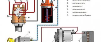
Carburetor engine ignition system
Ignition is contactless.
Consists of a distribution sensor, switch, ignition coil, spark plugs, ignition switch and high and low voltage wires. A small number of cars with a 1600 cc engine were equipped with a microprocessor engine control system, which is not described here. The ignition distributor sensor 3810.3706 is a four-spark type, with a contactless control pulse sensor and built-in vacuum and centrifugal ignition timing regulators. The initial ignition timing angle at a crankshaft speed of 750–800 rpm should be 1±1° BTDC.
The distribution sensor performs two main functions: firstly, it sets the moment of spark formation depending on its initial setting, the number of revolutions of the crankshaft and the load on the engine, and secondly, it distributes high voltage pulses (“spark”) among the cylinders in accordance with the order of their operation - a rotor (runner) is used for this. In order to avoid mistakes during assembly, the slider is installed on the support plate of the centrifugal regulator in only one position. The slider has a 1 kOhm noise suppression resistor.
The operation of a contactless sensor is based on the Hall effect. When the ignition is turned on, power supply is supplied to the sensor. When the sensor-distributor roller rotates, a steel screen with rectangular cutouts passes through the sensor gap. While there is a screen plate in the gap, the voltage is removed from the control terminal of the sensor; as soon as there is a cutout in the gap, the voltage at the control terminal drops sharply. Thus, the contactless sensor produces four rectangular pulses (according to the number of cutouts in the screen) for each revolution of the distributor shaft, which corresponds to the ignition moment in each of the engine cylinders.
You can check the functionality of the contactless sensor by assembling the circuit shown in the figure. Slowly rotating the ignition distributor shaft, monitor the voltmeter readings. The voltage should change sharply from the minimum (no more than 0.4 V) to the maximum (no more than 3 V less than the supply voltage). A faulty sensor cannot be repaired (except for a break in the wires between the sensor itself and the block on the sensor-distributor housing). If a steel screen with slots touches the sensor (determined by slight jamming or a scratching sound when the roller rotates, as well as visually after partial disassembly of the distributor sensor), check the axial play of the roller and the fit of the screen. If necessary, replace the distributor sensor.
The centrifugal regulator increases the ignition timing with increasing engine speed, coming into operation at 900–1400 rpm. When the sensor-distributor roller rotates, the regulator weights diverge under the action of centrifugal forces, overcoming the resistance of the springs, and shift the support plate of the centrifugal regulator clockwise relative to the roller. For optimal operation of the regulator, the springs have different stiffnesses. A stiffer (thicker) spring comes into operation later, approximately in the middle of the full stroke of the plate - therefore it is put on the stand with a gap, while a softer (thin) spring is always tense. The maximum movement of the support plate is limited by the cutout in it and is about 12° along the distributor, which corresponds to an ignition timing angle of about 24° along the crankshaft.
When inspecting the centrifugal regulator, make sure that the weights move freely on the axles, their damper plastic rings are not lost, the thin spring is tensioned, and the support plate returns under the action of the springs to its original position. If necessary, lubricate the distributor shaft with a few drops of engine oil.
The vacuum regulator increases the ignition timing depending on the engine load. It consists of a vacuum chamber with a steel spring-loaded membrane, which is connected by a rod to the base plate of the proximity sensor. Under the influence of vacuum, the membrane bends, overcoming the resistance of the spring, and turns the support plate counterclockwise. The maximum movement is limited by the cutout on the rod and is about 9° at the distributor (18° at the crankshaft).
The vacuum for the operation of the vacuum regulator is taken from the hole in the mixing chamber of the carburetor opposite the throttle valve of the first chamber. When the damper is partially opened (partial load), the vacuum behind it is large, and the regulator shifts the moment of spark formation as much as possible towards the advance. When the damper is fully opened (full load), the vacuum behind it drops, and the regulator returns the contactless sensor support plate to its original position.
You can roughly assess the serviceability of the vacuum regulator directly on the car. With the engine running, disconnect the vacuum hose leading to the regulator from the carburetor fitting. If you now create a vacuum in the hose (you can use your mouth), the engine speed should increase, and when the vacuum is removed, it should decrease again. The vacuum should remain for at least a few seconds if the hose is pinched. You can visually verify the functionality of the vacuum regulator by partially disassembling the sensor-distributor
and supplying vacuum to the inlet fitting of the regulator. In this case, the screen of the sensor-distributor should rotate at an angle of 9±1°, and when the vacuum is removed, it should return back without jamming.
Tools and Diagnostics
ATTENTION! A completely simple way to reduce fuel consumption has been found! Don't believe me? An auto mechanic with 15 years of experience also didn’t believe it until he tried it. And now he saves 35,000 rubles a year on gasoline! Read more"
Tools are an important part of any job. They will be needed to make adjustments to the process of issuing SOP. Mandatory tools include screwdrivers, a measuring instrument, wrenches, and preferably a laptop with a specially installed program designed for diagnosing injection-type power units.
First, you should know that on an injection engine, electronics are responsible for driving the car. It is subordinate to the head – the computer system. Conducting quality testing of all components of the injection system is the first thing to do.
Here's how it's done:
- the ignition is turned on;
- the supply of fuel by the electric fuel pump is checked (the characteristic sounds of activation of the pump performing the injection should be heard).
If there are no sounds of the fuel pump operating, you need to check the relay that controls the operation of the pump.
You should also pay attention to the instrument panel, on which the indicator may indicate. If this is the case, then you need to connect a laptop with a special program to the BC system. It will help you analyze errors and display them in a list.
If no problems are identified at this stage, then it’s time to start the internal combustion engine. On a functioning engine, the throttle assembly is checked first.
Here's how it's done:
- first, an external inspection of the sensor, which is responsible for the position of the damper, is carried out;
- then the wiring condition is tested;
- if everything is in order, it would not be superfluous to measure the voltage of the entire circuit and sensor using a measuring device;
- the obtained values must be compared with the standard indicators specified in the vehicle repair manual.
A normal current value can be considered to be in the range of 0.45-0.55V. The current value should not exceed 12 V, and the throttle opening degree should not be more than 1%. If deviations are noticed, then you need to adjust the throttle drive so that it closes the damper entirely.
Next, you need to press the gas pedal all the way, re-measuring the indicators this way. The damper open level should be 90%. As for the sensor voltage, the voltage must be 4.5 V.
Throttle actuator tuning is considered an important part of the work included in the diagnosis. It allows you to simultaneously set up a node and check the consistency of the values.
In order to adjust the drive you need to:
- disable the RDPV (sensor responsible for additional air flows);
- half open the throttle;
- make adjustments so that the damper completely covers the hole.
Distributor VAZ 21213 installation adjustment
Installation of ignition timing General Information
Marks for setting ignition timing
1 – sign v.m.t. on the crankshaft pulley; 2 – ignition advance sign by 10°; 3 – sign of ignition advance by 5°; 4 – 0° ignition advance sign
Ignition timing up to TDC at a crankshaft speed of 750–800 rpm, it must comply with the data in subsection 1.11.
To check the ignition timing, there are three marks 2, 3 and 4 on the cover of the gas distribution device and mark 1 on the crankshaft pulley, corresponding to the t.m.t. piston in the first and fourth cylinders when they coincide with mark 4 on the cover.
You can check and set the ignition timing using a strobe, proceeding in the following order:
– connect the “plus” clamp of the strobe light to the “plus” terminal of the battery, the ground clamp to the “minus” terminal of the battery, and connect the clamp of the strobe sensor to the high voltage wire of the 1st cylinder. For better visibility, mark mark 1 on the crankshaft pulley with chalk;
– start the power unit and direct the flashing strobe light at the mark on the pulley; If the ignition timing is set correctly, then when the engine is idling, the position of the mark on the pulley should correspond to the data in Appendix 3.
To adjust the ignition timing, stop the engine, loosen the nut securing the ignition distributor and turn it to the required angle. To increase the ignition timing angle, the distributor sensor housing should be turned counterclockwise, and to decrease it, clockwise. Next, measure the ignition timing again.
To make it easier to adjust the ignition timing, there are divisions and “+” and “–” signs on the flange of the ignition distributor. One crushing on the flange corresponds to eight degrees of crankshaft rotation.
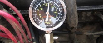
If you have a diagnostic stand with an oscilloscope, then with its help you can easily check the installation of the ignition timing, following the instructions for using the stand.
Install the ignition distributor sensor removed from the engine to the area in the following order:
How to adjust the ignition on a Niva with a carburetor engine with your own hands
Unpretentiousness, ease of maintenance and maintainability are a well-known advantage of all carburetor engines that were installed on cars of the VAZ family, including the entire Niva model range. But here also lies their main drawback, namely the need for periodic manual adjustments. For example, after repairs or when changing the octane number of the fuel used, the driver is required to install the ignition on a VAZ Niva car (carburetor), while injection systems do not require such manipulations.
Installing the ignition on the Niva eliminates the problem of incorrect engine operation
Due to an incorrectly set ignition timing, the engine begins to operate incorrectly and its power decreases. Timely adoption of measures to install the ignition on a VAZ-21213 Niva with a carburetor engine can eliminate the problem. If you decide to make all the adjustments yourself, you can also save on the services of a specialist. To do this, you just need to read the guide below.
VAZ-21213 (Niva). Setting the ignition timing
What methods of adjusting the ignition on a VAZ Niva car with a carburetor engine can be used at home? Detailed guide to setting the ignition timing.
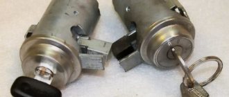
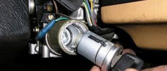
Features of replacing the ignition switch
First of all, it is important to make sure that the problem is in the lock. Therefore, the spark plugs, distributor and ignition coil are inspected. Often these parts of the internal combustion engine become the reason for failures of correct operation. If breakdowns in them are excluded, then the ignition switch (IZ) should be replaced. Removal order:
- Disconnect battery.
- Remove the steering column.
- Mark the wires going to the 3Z contact area. Using a flat-head screwdriver, unscrew the bolts securing the switch to the steering column (left and right).
- Insert the key into position 0. By pressing the screwdriver, press the lock slightly through the hole (do not touch the key).
- Lightly pull the 3Z towards you and dismantle it. The ignition switch Niva 21213 is switched off according to the wiring diagram (the contact part is changed if required). To do this, be sure to remove the retaining ring with a screwdriver.
- Remove the key, install the contact part so that the wide protrusions of the body and the parts coincide.
- The remaining parts are assembled in the reverse order.
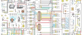
If you strictly follow the instructions and wiring diagram, no problems should arise. This is facilitated by the simplicity of the design. Moreover, the part can even be repaired if the damage is not critical.
We change the distributor on our own | Repair of Niva VAZ 2121
In order to remove and subsequently replace the distributor on a VAZ 2121 Niva, we will need the following tool:
- Pliers
- Open-end or socket wrench 13
Peculiarities
The operation of the Niva 21213 system depends on the condition of its parts. High-voltage wires must have a distributed resistance, the value of which is in a certain range. Too much resistance will result in the ignition coil not having enough power to cause a breakdown. Low resistance increases interference. Although, some install just such wires. Of course, the spark power will increase and engine performance will improve. Spark plugs can lose their properties over time. The electrodes melt and carbon deposits appear.
The high temperature inside the cylinders greatly heats the spark plugs. Therefore, even when the ignition is turned off, ignition occurs from heated spark plugs.
It is important that all spark plugs have the correct gap between the electrodes. This will ensure high-quality ignition of the mixture. The distributor cover must be clean from dirt, since its presence can lead to current leakage.