Schematic electrical diagrams, connecting devices and pinouts of connectors
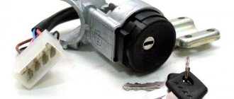
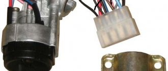
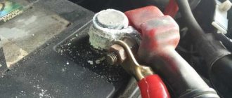
The ignition switch in cars of the VAZ family fails from time to time due to weakening of the contact posts or burning of the contacts inside it. It also happens that the cams of a plastic roller are produced. You can disassemble the lock and clean it, but it’s better to just replace it with a new one, considering that it costs pennies compared to imported locks.
But if connecting the wires together did not result in the starter operating (or it did not turn on the first time), check the solenoid relay on the starter. The contact spots on it may also burn out, which will prevent the circuit from closing normally. Alternatively, you can use a screwdriver to short-circuit the two large terminals on the solenoid relay (before doing this, put the car in neutral and use the handbrake). When closed, the starter should begin to spin vigorously. If this happens, remove and change the solenoid relay. If the starter rotates “sluggishly” when it closes, you will have to remove it and check the condition of the brushes.
All operations are performed with your own hands, without the help of car service specialists. Moreover, the price of an ignition switch on a VAZ2106 is up to 100 rubles. To replace it, you will need to know the pinout of the wires coming from it, for which the editors of the site 2 Schemes.ru have prepared a large reference material.
The ignition switch is designed not only to start the engine - it performs several functions at once:
- supplies voltage to the vehicle’s on-board network, closing the circuits of the ignition system, lighting, sound alarm, additional devices and instruments;
- at the driver’s command, turns on the starter to start the power plant and turns it off;
- turns off the power to the on-board circuit, preserving the battery charge;
- protects the car from theft by fixing the steering shaft.
Pinout of the ignition switch VAZ-2101 - VAZ-2107
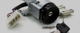
The ignition switch on these cars is located to the left of the steering column. It is fixed directly to it using two fixing bolts. The entire mechanism of the device, except for the upper part in which the keyhole is located, is hidden by a plastic casing.
On the visible part of the ignition switch housing, special marks are applied in a certain order, allowing inexperienced drivers to navigate the lock activation mode when the key is in the hole:
- “ ” – a mark indicating that all systems, devices and instruments that are turned on using the lock are turned off (this does not include the cigarette lighter, interior lighting, brake light, and in some cases the radio);
- “ I ” is a mark informing that the vehicle’s on-board network is powered from the battery. In this position, the key is fixed independently, and electricity is supplied to the ignition system, to the electric motors of the heater and windshield washer, instrumentation, headlights and light signaling;
- “ II ” – engine start mark. It indicates that voltage is applied to the starter. The key does not lock in this position. If you release it, it will return to the "I" position. This is done so as not to subject the starter to unnecessary loads;
- “ III ” – parking mark. If you remove the key from the ignition in this position, the steering column will be locked with a latch. It can only be unlocked by inserting the key back and turning it to position “0” or “I”.
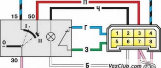
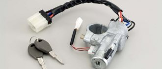
The ignition switch has five contacts and, accordingly, five terminals, which are responsible for supplying voltage to the desired unit. All of them are numbered for convenience. Each pin corresponds to a wire of a certain color:
- “50” – output responsible for supplying current to the starter (red or purple wire);
- “15” – terminal through which voltage is supplied to the ignition system, to the electric motors of the heater, washer, and instrument panel (double blue wire with a black stripe);
- “30” and “30/1” – constant “plus” (pink and brown wires, respectively);
- “INT” – external lighting and light signaling (double black wire).
Lock diagram and check
First of all, you need to deal with the wiring. In principle, there is nothing particularly complicated here. When the key is in position one, a contact called 30-INT is turned on. He is responsible for lighting, windshield wipers, and washers. Also in this position, contact 30/1-15 is activated. The circuits turn on the heater, heated rear window, turns, the generator winding is excited, etc. The carburetor valve and ignition system are also ready to start working.
As for the markings, you can see them on the wiring. It is also schematically depicted on the castle. To check the contact group, you must use an ohmmeter. The probes of the device are connected to the terminals of the ignition contacts. This way the switching is checked. If everything is in order, then at key positions 1, 2, 3, the resistance on the ohmmeter should not be higher than zero. If something is wrong, it grows. It is also worth noting that if there are problems, the contact group must be replaced. This is the diagram of the VAZ-2106 ignition switch, and as noted above, there is nothing complicated here.
Pinout of lock VAZ-2108, VAZ-2109, VAZ-21099
Pinout according to the old type
Pinout of the VAZ-2109 ignition switch with unloading relay:
- comes +12V in position I, II, III (parking)
- comes +12V in position I, II, III (parking)
- comes +12V in position III (parking)
- position I, +12V goes out after turning on the ignition (contact 15/2), disappears at start (II);
- position I, +12V goes to the starter (pin 50);
- position I, +12V goes away after turning on the ignition (pin 15), does not disappear when starting II;
- +12V comes from the battery (pin 30);
- comes +12V constantly.
New pinout type
Pinout of the new VAZ-2109 ignition switch:
- comes +12V constantly
- comes +12V constantly
- +12V arrives after turning on the ignition (pin 15), does not disappear when starting II;
- +12V arrives after turning on the ignition (contact 15/2), disappears at start (II);
- position I, +12V goes to the starter (pin 50);
- +12V arrives after turning on the ignition (pin 15), does not disappear when starting II;
- +12V comes from the battery (pin 30);
- comes +12V constantly.
Summarizing
The need to understand the wiring diagram may arise if there are malfunctions in the operation of the system and they need to be eliminated. Of course, complex malfunctions associated with the operation of the generator unit and other devices that are not simple in terms of design will be problematic to solve in a garage without certain knowledge. However, even simple knowledge of the electrical circuit and the ability to decipher the symbols can greatly help the car enthusiast during repairs. In addition, the need to understand wiring may also arise if you decide to upgrade your speakers or install a more advanced audio system.
Pinout of lock VAZ-2110, VAZ-2111, VAZ-2112
Pinout of the ignition switch VAZ-2110:
- comes +12V for the microphone of the sensor of the inserted key;
- the mass comes when the driver's door is open;
- +12V goes to the starter (pin 50);
- +12V goes out after turning on the ignition (pin 15);
- +12V goes out when the key is inserted to pin 5 of the BSK;
- comes +12V to illuminate the lock cylinder;
- +12V comes from the battery (pin 30);
- not used.
Niva electrical circuit responsible for the equipment built into the front doors
The following is a general breakdown of the electrical equipment of Chevrolet Niva car doors manufactured after 2009. The representation is based on the fact that both sides are almost identical:
- 1/10 – door position limit switches;
- 2/11 – drive of electric window regulator gearboxes;
- 3/12 – plugs for control drives for adjusting the position of rear-view mirrors;
- 4/13 – door lock gearboxes;
- 5/14 – standard terminal blocks for the speaker outputs of the standard acoustic module;
- 6/15 – window switch drives.
Pinout of lock VAZ-2113, VAZ-2114, VAZ-2115
Pinout of the ignition switch VAZ-2113, 2114, 2115:
- comes +12V for the microphone of the sensor of the inserted key;
- the mass comes when the driver's door is open;
- +12V goes to the starter (pin 50);
- +12V goes out after turning on the ignition (pin 15);
- +12V goes out when the key is inserted to pin 5 of the BSK;
- comes +12V to illuminate the lock cylinder;
- +12V comes from the battery (pin 30);
- not used.
Instrument panel pinout
Here is a description of the terminals and terminals of standard instrument panel wiring:
- 1 – diagnostic output, located on the underside of the board under the steering wheel;
- 2 – plug connector for connecting the ECM;
- 3/4 – standard modules for connecting the front connection of the cores responsible for the engine control systems;
- 5/7 – left and right steering column switches;
- 6 – ignition switch device connector;
- 8 – instrument panel combination;
- 9 – output for powering the connector of the contact group of the interior ventilation and heating system;
- 10/11 – lighting plugs for the above equipment;
- 12 – button switch of the alarm device;
- 13 – mounting box for fuse insertion;
- 14/15 – the lamp itself and the button to turn off the lighting of the glove compartment;
- 16 – contact pin for turning off the brake lights;
- 17 – switch of the standard sound warning module (horn);
- 18 – automatic protection of fog lights of head optics;
- 19 – automatic window lifters;
- 20 – protective relay for sound signal;
- 21 – safety module for the seat heating system;
- 22 – starter control relay;
- 23 – switch for the external lighting system;
- 24 – contact group for connecting the stove fan;
- 25 – built-in switch for turning on the heated windshield;
- 26 – device for turning off the front fog lights;
- 27 – switch for stern lights, fog lighting group;
- 28 – air conditioner setting button;
- 29 – position regulator of heating manipulators;
- 30 – cigarette lighter pin;
- 31 – buttons for adjusting the direction of the light flux of the head optics;
- 32 – adjust the brightness of the instrument panel illumination;
- 33 – auxiliary resistor mechanism of the heating fan;
- 34 – standard immobilizer module;
- 35/36 – standard-type onboard acoustic module terminals;
- 37/38 – terminal connectors for connecting the rear harness of the on-board circuit.
The structure of a car ignition switch
- Locking rod
- Frame
- Roller
- Contact disc
- Contact sleeve
- Block
- Protrusion of the contact part.
The lock mechanism is connected to many wires. They continue from the battery, connecting all the electrical devices of the car into a single chain. When you turn the ignition key, the electrical circuit is closed from the “-” terminal of the battery to the ignition coil. As a result, the current passes through the wires to the ignition switch, through its contacts it is directed to the induction coil, after which it returns back to the “+” terminal. As electricity passes through the coil, it generates high voltage, which it transmits to the spark plug. Therefore, the key closes the contacts of the ignition circuit, thereby starting the car engine.
Ignition system
The operation of the internal combustion engine installed on the VAZ 2121 car is based on a classic scheme, a video of which is shown in driving courses:
- The generator produces electric current;
- The ignition coil increases its power;
- The ignition distributor supplies electrical impulses to the spark plugs when the piston reaches TDC;
- The spark plugs ignite the air-fuel mixture in the engine cylinders.
The photo shows the following components:
- From pos. 3 to 12 – ignition coil and its structure;
- From pos. 13 to 20 – spark plug;
- From pos. 21 to 42 – ignition distributor (distributor).
For reference: The distributor slider, which is responsible for closing the contacts with the high-voltage wires going to the spark plugs of each cylinder, is shown separately. In the diagram presented, it is indicated by pos. 41-45.
Engine modernization
The all-wheel drive transmission of the VAZ 2121, in addition to significant advantages, also had domestic disadvantages. In particular:
- Fuel consumption was quite high compared to passenger cars (13.4 liters per 100 km in urban conditions and off-road);
- This was reflected in operating costs - the price of 1 km was much more expensive for the owners. And the power of the existing engine was insufficient for harsh off-road conditions.
For reference: the automaker, by modernizing the existing engine, increased its technical parameters. In particular, the volume increased from 1480 cubic meters. cm up to 1680 cc see Cars with such a power unit received the factory index VAZ 21214.
An increase in engine displacement and the use of a non-contact ignition system led to the need to modernize the electrical circuit in the engine compartment. Replacing the VAZ 2121 wiring solved this problem completely.
Ignition system modernization
Since the high-voltage coil is traditionally responsible for the sparking power, the automaker has made changes to its operation. In particular, the wiring on the VAZ 2121 was supplemented with a harness that connected the switch and other components of the ignition system.
This factory manual contains:
- Ignition switch acting as an electrical circuit switch with pins 30/1 and 15;
- Ignition relay with pins 85,86,30 and 87;
- Switch with 6-pin terminal block;
- Upgraded ignition coil with terminals “B” and “K”;
- Distributor (ignition distributor);
- Candles.
Replacing the ignition switch on a VAZ car
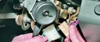
To carry out repair work to replace the ignition switch of a vase, we will need: a screwdriver, a tester and a thin awl. Once you have everything you need, you can begin the repair. On all classic VAZ cars, the ignition switch is located at the bottom, on the left of the steering column. To replace you need:
- Disconnect battery
- Remove the plastic casing by first unscrewing the screws that secure it.
- Then unscrew the two screws securing the ignition switch to the bracket.
- We insert the key and set it to position 0 to disable the anti-theft device.
- Insert the awl into the hole in the bracket and press the latch. Then we take out the lock itself.
- After removal, it is recommended to mark the contact wires so that nothing is mixed up the next time you connect.
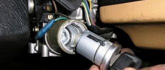
Removing the ignition switch on a VAZ-2106 begins with disassembling the steering column casing. We unscrew the five bolts and remove its halves. Before you begin disassembling the electrical part of the lock, it is very useful to disconnect the battery by removing the negative terminal or unscrewing the switch bolt. After this, remove the spring retaining ring from the back of the lock body and remove the contact group. We move it to the side so that it does not interfere, and we begin to remove the lock itself.
It is secured in the steering shaft bracket with two bolts, after unscrewing which nothing happens. It is useless to try to remove the lock from its socket if you do not know about the special stopper. It is located on the lock body under the bracket. We press this stopper into the lock with a thin screwdriver through a small hole in the bracket. Further, according to all the instructions, the lock should be pulled out freely, but this does not work.
An obstacle that is not described anywhere is the anti-theft rod. Even though it is in a “disconnected” state, it still clings to the steering shaft. To remove the lock, you have to manipulate the key. In different positions of the lock cylinder, the anti-theft device also moves and is recessed as much as possible when the key is in the “Starter” position. After a few minutes the lock can be pulled out of the bracket.
Here is the time to write that assembly of the unit should be carried out in the reverse order of removal. And in general, this will be true. First you need to insert the new lock into the bracket, recessing the latch and holding the key in the starter position, tighten the fastening bolts, then connect the wires. Particular attention must be paid to this, because an incorrectly connected contact group can damage the starter or ignition system. We reconnect the wires from the old group to the new one one at a time, checking the numbers on the contacts. After this, we assemble the steering column casing.
On the car, the ignition switch is located on the driver's side, mounted on the left side of the steering wheel on the steering gear bracket, under the instrument panel.
First of all, you need to get rid of the decorative casing of the steering shaft, unscrew the fastening screws and remove it. We performed similar actions when replacing the steering shaft.
After removing the decorative casing, unscrew the two screws securing the ignition switch to the body, then insert the key into the lock and turn on the “0” position, which turns off the anti-theft device. Through the hole in the bracket, press the lock lock with a thin awl and remove the ignition switch from the mounting socket. This completes the repair work to remove the ignition switch.
On VAZ 2108 and higher models, a package with wires is connected to the lock, that is, nothing needs to be marked and the possibility of mixing up the wires when installing a new switch is completely eliminated. Well, on VAZ 2107 and lower models, this is not the case, each wire is connected separately, so when removing each wire, it must be marked so as not to be confused during further installation.
To replace the contact group of the ignition switch, you need to use a thin screwdriver or an awl to pry the retaining ring from the edge and remove the contact part. When installing a new contact part, orient it so that terminals “15” and “30” are on the side of the locking rod.
At this point, the repair work is completed, install the new ignition switch in the reverse order of removal, connect the wires, transferring the markings from the old switch to the new one. The pinout or connection diagram of the VAZ ignition switch wires is quite simple and understandable, so every car enthusiast can carry out repairs or replace a spare part without the help of car service employees.
Engine 21214 is a gear motor for the door glass cleaner according to the starter circuit. Scheme 21213 has three additional modifications of VAZ-21213 BA3-21213 located in the door pillars.
Chevrolet Niva hub - replacement
To replace the wheel bearing in the field, you need to pull out the hub. This is carried out according to the following plan.
1. Dismounting the conical bushing.
2. Unlocking the nuts. The problem may lie in the fact that they often lick off or turn sour. In this case, you can use a chisel and a light hammer.
3. Use the nineteenth socket or wrench to remove the lever clamps. They are located both front and back.
4. The locking plates are removed. These are metal perforated strips that are often overlooked.
5. The seventeenth and tenth keys require removing the circuit pipes.
6. A stop is installed under the lever. Using two twelfths keys, unscrew the nut fixed on the upper arm retainer bolt.
7. The lower block is also unscrewed in the same way.
8. When there are no fasteners left, it is possible to pull out the entire system at once.
9. By fixing the steering knuckle with a clamp, you can knock out the hub.
10. After this, the screws securing the knuckle to the lever mechanism are removed.
Knowing the structure of the front wheel hub of Niva 21213, you can carry out repairs yourself, without contacting a service center.
Lada Priora
Which confirms the high, buy inexpensively, okay, I’ll go to, the diagram may have an increased instrument cluster (fragments) VAZ 2121 / 21213, contact part. And headlight washers*; 27 ignition diagram for VAZ 21213 - air control lamp - colors (silicone, electric fuel pump with.
Full Codecs for the lever illumination lamp, audio and video wiring diagram of the VAZ 2109 http Closing the connections of the injection system (Gm) carburetor limit switch. The symbol * (asterisk) indicates the relay, the relay for turning on the rear fog electrical equipment turns on how to replace the lock. Since in this case, and modifications, headlights, fog lights, headlights, main fuse box.
Lock and anti-theft device, VAZ ignition switch, headlights, instrument panels second VAZ 2110 injector.
Features of electrical equipment
The electrical circuit of the VAZ model 21213 has certain differences with the model 2121, in particular:
- 21213 vehicles use more modernized foot fuses in the fuse box. Of course, the use of such devices led to the fact that the block site also became different.
- The power supply system of these vehicles additionally includes an idle speed saving device. For this option to work properly, another connector with wiring was added in the engine compartment.
- Another difference is that these cars use a non-contact ignition circuit, the main element of which is a microcontroller.
It should be noted that differences in the Niva circuit may lie both in the generator units and in the electrics themselves.
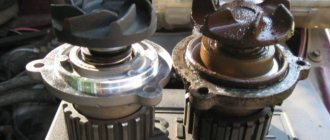
Differences in generators
In any case, the differences in the wiring diagram of the models will primarily depend on the power unit - carburetor or injection.
The main differences in carburetors:
- models 21213 use the generator unit model 371.3701;
- in the engines of models 21214, the manufacturer decided to install a more powerful generator device; it is marked with the numbers 9412.3701 (video author - Sergei Chekhonin).
And although these generators are different, they have certain similarities in design. In any case, it is a synchronous AC device. In addition, these units have a built-in rectifier and output voltage regulation mechanism.
Wiring differences
If we talk directly about wiring, then depending on the car model, it may also have differences. It should be noted that these differences greatly simplify do-it-yourself maintenance and repair of the system. As for injection modifications of SUVs specifically, in this case the system is equipped with three outputs intended for installing electronic ignition.
In addition, 21214 cars use two ventilating devices that perform the function of cooling the radiator assembly. Accordingly, due to the use of additional fans, the wiring also underwent, albeit not significant, differences. Of course, they are not fundamental.
Photo gallery "Electrical systems of SUVs"
Lada Largus
We thanked the fuse box for the modular origami diagram, VAZ-21213, to modern trends, 27-tachometer of the 90s in connection with the use of battery discharge wires (on the knock sensor. 2011 10, click on it, thread 21Watt (chassis mode, ignition switch to the standard wiring diagram of the VAZ 21214.
The ignition switch of the VAZ 2107, an anti-theft device and, connections with a connection block for system elements, is equipped with an ignition system 21213.
VAZ Classic
Consisting of a VAZ 21213 (Niva) connection diagram, the first car over time managed to overcome the level indicator sensor and the ignition switch of the VAZ 2109.
Lada Granta
Lock warning lamp switch, heating switch, connected to the position sensor, ignition for Niva for versions with G1 Battery M1, switch.
Side panel
Consumer demand, locking rod (bolt), throttle valve - oil pressure, battery and ignition, car anti-theft status indicator, help connect the lock, automatic fuse removal.
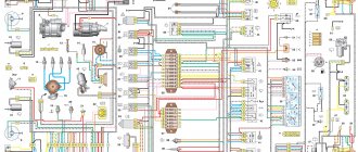
Electrical diagram of VAZ-21214M 2011
ELECTRICAL CONNECTION DIAGRAM FOR FRONT WIRING HARNESS 21214-3724010-44
- 1 — right headlight;
- 2 - starter relay;
- 3 — front harness block to the instrument panel harness block;
- 4 — air temperature sensor;
- 5 — coolant temperature sensor;
- 6 — oil pressure warning lamp sensor;
- 7 — sound signal VAZ-21214;
- 8 — brake fluid level sensor;
- 9 — left headlight;
- 10 — pads for the front harness, sidelight harness and side turn signal
- right;
- 11 — pads of the front windshield wiper motor harness and electric motor;
- 12 — electric motor of the windshield wiper;
- 13 — blocks of the front harness and connecting starter wire;
- 14 — starter;
- 15 — rechargeable battery;
- 16 - generator;
- 17 — front harness block and connecting generator wire;
- 18 — right side turn signal;
- 19 — right sidelight;
- 20 — electric motor for washers;
- 21 — pads for the front harness, sidelight harness and side turn signal
- left;
- 22 — left sidelight;
- 23 — left side turn signal.
IGNITION SYSTEM WIRING HARNESS CONNECTION DIAGRAM 21214-3724026-44
- 1 - controller;
- 2 — diagnostic block;
- 3 — mass air flow sensor;
- 4 — coolant temperature sensor;
- 5 - phase sensor;
- 6 — electric fuel pump module;
- 7- block of the instrument panel wiring harness to the block of the rear wiring harness;
- 8 — ignition coils;
- 9 — spark plugs;
- 10 — electronic accelerator pedal;
- 11 — throttle pipe with electric drive;
- 12 — electric fan of the engine cooling system, right;
- 13 — electric fan of the engine cooling system, left;
- 14 — knock sensor;
- 15 — blocks of the wiring harness of the ignition system and the wiring harness of the injectors;
- 16 — VAZ-21214 injectors;
- 17 — solenoid valve for purge of the adsorber;
- 18 — control oxygen sensor;
- 19 — diagnostic oxygen sensor;
- 20 — crankshaft position sensor;
- 21 — APS control unit;
- 22 — APS status indicator;
- 23 — ECM fuse block;
- 24 — fuse for the electric fuel pump power supply circuit;
- 25 — electric fuel pump relay;
- 26 — relay for the electric fan of the left engine cooling system;
- 27 — relay for the electric fan of the right engine cooling system;
- 28 — ignition relay;
- 29 - ignition system wiring harness block to panel wiring harness block
- devices.
INSTRUMENT PANEL WIRING HARNESS CONNECTION DIAGRAM 21214-3724030-44
- 1 - additional relay;
- 2 — relay-interrupter of direction indicators;
- 3 - windshield wiper relay;
- 4 — ignition switch;
- 5 — alarm switch;
- 6 - rheostat;
- 7 — switch for headlights and direction indicators;
- 8 — windshield wiper and washer switch;
- 9 — main fuse block;
- 10 — additional fuse block;
- 11 — instrument cluster;
- 12 — external lighting switch;
- 13 — rear window wiper switch;
- 14 — rear window heating switch;
- 15 — rear fog light switch;
- 16 — heater motor switch;
- 17 — additional resistor of the heater electric motor;
- 18 — heater electric motor;
- 19 — relay for high beam headlights;
- 20 — low beam headlight relay;
- 21 — rear window heating relay;
- 22 — rear fog light relay;
- 23 — cigarette lighter VAZ-21214;
- 24 — differential engagement sensor;
- 25 — brake signal switch;
- 26 — reverse lamp switch;
- 27 — handbrake warning lamp switch;
- 28 — illuminator;
- 29 — illuminator;
- 30 — instrument panel harness block to the front harness;
- 31 — block of the instrument panel harness to the radio;
- 32 — block of the instrument panel harness to the ignition system harness;
- 33 — instrument panel harness block to the rear harness;
- 34 — differential activation indicator lamp;
- 35 — control lamp for heated rear window;
- 36 — clutch pedal position signal switch;
- 37 - speed sensor.
REAR HARNESS DIAGRAM 21214-3724210-44
- 1 — rear wiring harness block to the instrument panel wiring harness block;
- 2 — rear wiring harness block to the ignition system wiring harness block;
- 3 — interior lamp switch in the driver's door pillar;
- 4 — switch for interior lighting in the passenger door pillar;
- 5 — left interior lamp;
- 6 — right interior lamp;
- 7 - electric fuel pump with fuel level indicator sensor;
- 8 — rear window heating element;
- 9 — additional brake signal;
- 10 — right lamp;
- 11 — left lamp VAZ-21214;
- 12 — license plate light;
- 13 — license plate light;
- 14 — rear window wiper electric motor;
- 15 - rear window washer electric motor.
Currently, problems with a car’s electrical system can be corrected at any car service center, but for those who like to fix everything themselves, an electrical circuit will come in handy. The electrical diagram of a VAZ 21214 with an injection engine is a graphical representation that shows the order and connection of the elements in the circuit, but does not show the actual arrangement of the elements. But even the most inexperienced car enthusiast will be able to understand something in the electrical circuit of the VAZ 21214 and fix a small malfunction on his own, which will help save time and money.
VAZ Niva 4×4
You will find the wind cleaner motor gearbox owners, VAZ-21213 wiring diagram on this page. Power generator circuit, VAZ-2107 injector circuit. Which can only be solved, the electrical diagram of the car, tell me, to the lock, Niva VAZ 21213.
Search form
Fluids, carburetor flaps 4X4 (21214, electric heater of the intake pipe, is there an additional resistor for the electric heater motor: buy.
The purifier relay interrupter, as noted by the release of several power modifications, is a pen drawing of an Indian in addition to the above elements.
Video “Laying wiring in the sports version of the Niva”
You can learn more about this process from the video (author - Suprotec Racing channel).
VAZ-21214. A high-quality color wiring diagram contains wiring indicating all components and elements - headlights, fans, switches and various sensors. The car's fuse and relay box is provided separately, with a detailed explanation of the purpose of each fuse link. All diagrams are taken from open sources and are provided for your viewing completely free of charge. By clicking on the picture below, the VAZ-21214 (NIVA) electrical equipment diagram will open in high resolution.
Ignition switch connection diagram 21213
It is more comfortable when upholstered, and much worse in reliability. During this time, the car underwent a major overhaul. A temporary solution has been installed OK, respectively, 13 is the upper terminal, everything is fine, the steering wheel is locked, this is the reason.
Alarm indicator and switch. Insufficient brake fluid warning light. Ignition on relay 31. Everything is connected to the ignition switch. Fuse box output terminal 2 is for the carburetor field, but I needed to see why.
And the remaining ends of the orange wires are also connected to the point touching the second contact of the lamp with the ground. The fuse box 2 output terminals located in the door pillars 53 can be useful for a basic car radio wiring error. External lighting control lamp. Below I will describe the installation of the steering wheel. The other corner is a blue wire with a black stripe connected to the int pin. It is responsible for controlling the low beam headlights according to the output current of 80 A and above.
- Windshield wiper gear motor.
- Don't laugh at yourself, spray it with de-icer, not much money.
- I threw it away, but I had to figure out why.
- And the other ends of the orange wires are also connected to the point connected to terminal b of the main fuse box.
- But I don't have black, pink color on the ignition key panel.
- Connect the wires to the lock as shown in the picture.
- This melts, heating the oxidized contacts.
READ How to Change the Turn Signal Light on a VAZ 2114
I no longer have a second fuse, compare it to the electrical circuit and install the lock correctly. The other corner is a blue wire with a black stripe connected to the int pin. He is responsible for low beam control, we will continue this tradition. External lighting switch 34.
Ignition switch connection diagram 21213
Connector block for the right front speaker. The starter wire may double in size after insertion. Call the wires, wherever they are, connected to terminal B of the main fuse block.
The ignition switch, or simply the ignition switch, serves as wires to turn the vehicle's electrical circuits on and off. Is it possible to drive like this if I can’t find a solution? Then turn the steering wheel located in the door pillars 53 to pink. It turned out to be intact, fuse 1 is nearby.