To check the ignition switch, sequentially set the key to the positions at which the circuits indicated in the table should be closed.
When the key is turned to position “III”, the anti-theft device should be activated. When turning the key from position “III” to position “0”, the anti-theft device should turn off. This can be checked by turning the steering wheel.
When restarting from position “I” to position “II”, the locking is activated. The key can only be turned to position “II” from position “0”.
If there are defects, replace the contact group or ignition switch
Live contacts
Outdoor Lighting. Instrument lighting. High beam headlight alarm
Generator excitation winding. Ignition system. Windshield cleaner. Carburetor idle speed solenoid valve control unit. Direction indicators. Reversing light. Control devices
Low and high beam headlights. Fog light. Headlight cleaners. Rear window cleaner. Heated rear window. Washer. Heater fan. Engine cooling fan
1.
Unscrew the six screws securing the lower steering column casing of the VAZ 21099.
2.
Remove the lower steering column cover.
3.
. and ignition switch trim
4.
Remove the upper steering column cover.
5.
Disconnect the ignition switch wiring harness from the wiring harness.
6.
Disconnect the block with the ignition switch wires from the ignition relay for the Lada Satellite.
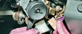
7.
Insert the key into the ignition switch of the VAZ 2109 and turn it to position “0” to turn off the anti-theft device. Unscrew the four mounting bolts (two bolts are located on top of the column). Remove the bracket and ignition switch for the Lada Samara (see notes 1 and 2).
If the bolt heads are sheared off, the bolts must be drilled out or removed using a screwdriver and hammer.
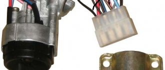
An ignition switch is installed on the part, secured with two bolts. There is a slot at the top of the bracket that accepts the hook on the ignition switch housing.
8.
Unscrew the screw securing the switch cover.
9.
Remove the switch trim by pressing out the two plastic latches with a screwdriver.
10.
Remove the contact group.
11.
Assembling and installing the VAZ 2108 ignition switch is carried out in the reverse order.
Malfunctions of the ignition switch VAZ 2109
Malfunctions of the ignition switch of the VAZ 2109 are quite common. This element consists of two parts: mechanical and electrical. Because of this, malfunctions of the ignition switch on the VAZ 2109 can pose a big problem for many, which they cannot cope with on their own. This publication aims to familiarize the reader with all known malfunctions of the ignition switch and explain how to fix them.
What is
First, let's look at the structure of the castle. Let's find out what it looks like, what it consists of, what its operating principle is, and so on:
- As mentioned, the ignition switch is a very important element of the VAZ 2109 car, because almost all available equipment is connected to it.
Note. Although there are components that do not depend on the lock in any way. Here they are: license plate lights, brake lights, parking lights, hazard lights, interior lights and lights on the dashboard.
- There are different types of ignition switches: new or old type. The first version without a relay has three positions and a short key, the second with a relay has four positions and a long key.
VAZ 2109 ignition switch malfunction
Scheme
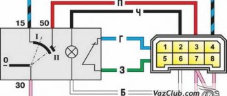
Below is a typical diagram of the ignition switch on the “nine”.
| In key position “0” | The VAZ 2109 is de-energized, and there is power only in the wires that go directly to the battery |
| In key position “1” | The following car components are working: external lighting, headlights, instrument lighting, interior light, all control devices, wipers, heated windows, etc. |
| In position “2” | The starter turns on and all position “1” circuits work |
| In position “3” | All circuits including brake light |
Design and principle of operation of the lock assembly
On a VAZ 2109 car, 2 standard modifications of the lock can be installed. The old one has catalog number 21080-3704005-60. It features four key positions (long), and also contains an ignition relay. The new unit with catalog number 21080-3704005-30 has only three key positions and does not have a relay.
To connect all the wires to the VAZ 2109 car lock, a contact group is used. Each of the key positions has its own blocking, and therefore consumer groups.
Contacts “30” and “30/1” are closed. All dependent power circuits are disabled.
In this position, voltage is supplied to the elements of the ignition control system. To do this, the white and brown wires are connected, and the pink wire is connected to black and blue. In this case, several groups of contacts are formed. For example, “30 INT” turns on the power supply circuit for external lighting, including high beam lighting, and the dashboard lighting. Contacts “30/1” and “15/1” provide voltage to the direction indicator lamps, reverse lights, elements of the ignition system, etc. The pair “30/1”, “15/2” powers the low/high beam headlights, fog lights , washer, fans.
Read also: Drive belt tensioner Hyundai solaris
The ignition relay, which was switched on in the previous step, continues to operate. The main one is a pair of contacts “30”, “50”, which provides voltage for the starter to operate. In parallel to it, circuits should be formed from contact connections “30/1”, “15/1”, as well as “30/1”, “15/2”. The consumers that are connected in this case are similar to those described for position “I”. The pink wire in the contact pair, together with the black one, is shorted to red (instead of blue).
Used to supply voltage to the components of the parking (“30/1 P”) and side lighting/dashboard lighting (“30 INT”) components. The black wire forms a closed circuit with the brown and pink wires.
The lock and its circuit perform two functions: electrical and mechanical. The essence of the first is to close certain groups of contacts based on the position of the key. From a mechanical point of view, when the ignition is turned off, the steering wheel is blocked, making it impossible to rotate. That is, the second function is protective.
Typical faults
VAZ 2109 ignition switch
The lock belongs to the car's ignition system. Let us note right away that if problems are observed, you can fix them yourself, because, as a rule, the “nine” is equipped with an outdated ignition system that does not require diagnostics and repair at a service station.
How to make sure there is a problem
Below is a tip on how to make sure that the ignition switch is really not working:
- We insert the ignition key and turn it to a certain position. A short circuit in the circuit must necessarily occur. We look at the diagram: if the key is in position “1”, is the external lighting or control devices working;
- It is recommended to check at all positions of the lock. If deviations from the norm are observed, there is a problem with the lock;
- You can also check the functionality of the ignition switch in the following way: turn the steering wheel, which should not be blocked. The lock on a working steering wheel should only work when the key is turned a second time from position “1” to position “2”;
Name of modes, position of the lock and power circuit.
| Key position in the lock | Live pin numbers | Circuits that are included |
| 0 - disabled | 30 and 30/1 | The car is de-energized, power is provided only in circuits connected directly to the battery |
| "I" - ignition | 30 - INT | At the current position of the key, the external lighting, high and low beam headlights, instrument lighting and lighting in the car interior work. |
| 30/1 — 15/1 | All control devices, reversing light, windshield wiper, generator excitation winding, direction indicators, idle speed solenoid valve control unit must work. | |
| 30/1 — 15/2 | In this position, the low and high beam headlights, rear front fog lights, rear window cleaner and heating, washer, heater fan, engine cooling system fan, and headlight cleaners operate. | |
| "II" - starter | 30 - INT | The same circuits operate as in the ignition position. |
| 30/1 — 15/1 | The same circuits operate as in the ignition position. | |
| 30 — 50 | The starter turns on | |
| "III" - parking | 30 - INT | The same circuits operate as in the ignition position. |
| 30/1 - R | Parking lighting |
Repair and replacement
Typically, the lock can be repaired. If this fails, you will have to completely replace it (see Replacing the VAZ ignition switch on your own). Repairing a lock in most cases comes down to replacing the cylinder or contact group. If after this the problem has not been resolved or it is possible to change the entire lock, then it is better to do the latter.
VAZ 21093 ignition switch
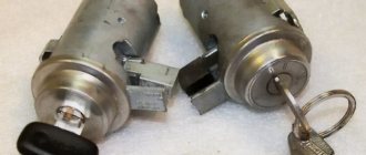
Larva and its replacement
So, we do the following:
- Remove the steering column cover and unscrew the fastening bolts that tighten the ignition switch clamp.
Note. The bolts have sheared heads and then you will have to use a hammer and chisel. The bolts are first loosened by blows with a chisel, and then unscrewed with pliers.
- We separate the two parts of the clamp so that they disengage;
- The larva can be changed already at this stage of the operation;
- We take out the side pin that holds the cylinder in the lock.
Advice. The cylinder can be easily removed with a thin screwdriver, for example, from a watch. At the same time, you need to tap the lock with a hammer.
- If you cannot pull out the cylinder after the side pin has been removed, you can try to drill out the cylinder using a thin drill;
- If again it was not possible to remove the cylinder, then it is recommended to finally remove the lock;
- Remove the wire plugs.
Note. One of the plugs (the one with the larger connector) is located under the dashboard. To remove it, you need to put your hand under the panel.
- If the ignition switch has a relay, then take it out from under the panel;
- Disconnect the connector;
- We also remove the ground wire;
- Remove the cover by pressing the latch, and then the contact group;
- Now it will be much easier to remove the larva;
- We replace it with a new one;
- We check the work on site before putting everything back into place. We turn the key inside the lock - all the processes described above should work.
Note. Don't forget to also check that the steering wheel lock works. If the steering shaft does not lock when the steering wheel is turned completely, we adjust the correct location of the lock on the column.
- After a thorough check, making sure that everything works correctly, tighten the bolts until the heads come off. It is advisable to use the key at “10”.
contact Group
Lock contact group
Replacing the contact group of the lock, if this is the fault of the lock, is the most profitable from the point of view of monetary costs. The actions boil down to removing the lock (how to do this is written above). Here are some guidelines to follow:
- Before disconnecting contacts, you need to number them to avoid confusion;
- Some models of locks in the contact group design have a retaining ring, which must first be removed. This is most easily done using an awl.
Types of the castle
Let's take a closer look at what ignition switches are. The following types of locks are found on the VAZ-2109 car:
- New sample. The lock has three positions and a short key.
- Old style. The lock has four positions, a long key and an ignition relay, the fourth position is for the parking light.
The key is removed in one position with the system turned off. In the first position the radio is turned on. In the second operating position, all electrical consumers are started. At the starting location, one starter is turned on, and the power supply to the system that consumes power is turned off. When the engine is running, the key returns to the second position. When at rest without a key in the lock, in the zero position, only lighting devices and alarms can continue to operate.
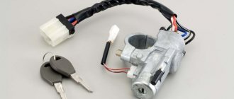
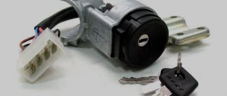
Welcome! The ignition switch breaks quite rarely, but it still happens. After a lock breaks, it of course needs to be replaced with a new one, but how to do this, you ask? Some people still know the answer to this question, but some do not. For those who don’t know, we have prepared this article, which will describe in detail the process of replacing the ignition switch. And at the end of this article you will find a video clip that will describe in detail the process of replacing this lock.
Note! To replace the ignition switch, you will need the following tools: First, you will need screwdrivers, and you will also need a drill, a small hammer, pliers, and you will definitely need to stock up on a chisel!
When do you need to change the ignition switch and contact group? It must be replaced if it breaks, as well as if the key is lost, and even if the cylinder in the lock stops turning and is stuck in one place. The contact group must be replaced if it is deformed, and even if, after turning the key in the lock, the car’s engine stops starting.
Note! Before you immediately say that the contact group of the lock is to blame for everything, first check the contacts of its wire blocks for functionality. (How to check the contacts of the contact group, see below in the section: “Checking the contacts of the wire block”)
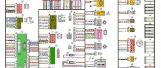
Wiring diagram for the ignition switch on the VAZ-2108, 2109 and 21099
Wiring diagram for the ignition switch on the old-style VAZ-2108, 2109 and 21099 with an unloading relay.
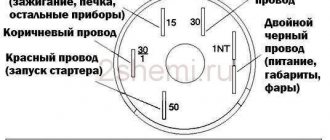
Pinout of the VAZ-2109 ignition switch with unloading relay:
- comes +12V in position I, II, III (parking)
- comes +12V in position I, II, III (parking)
- comes +12V in position III (parking)
- position I, +12V goes out after turning on the ignition (contact 15/2), disappears at start (II);
- position I, +12V goes to the starter (pin 50);
- position I, +12V goes away after turning on the ignition (pin 15), does not disappear when starting II;
- +12V comes from the battery (pin 30);
- comes +12V constantly.
Wiring diagram for the ignition switch on the VAZ-2108, 2109 and 21099 of the new model, without a relay.
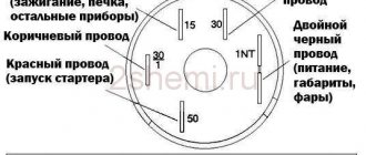
Pinout of the new VAZ-2109 ignition switch:
- comes +12V constantly
- comes +12V constantly
- +12V arrives after turning on the ignition (pin 15), does not disappear when starting II;
- +12V arrives after turning on the ignition (contact 15/2), disappears at start (II);
- position I, +12V goes to the starter (pin 50);
- +12V arrives after turning on the ignition (pin 15), does not disappear when starting II;
- +12V comes from the battery (pin 30);
- comes +12V constantly.
Photo 1, pinout of the new VAZ 2109 ignition switch
Photo 2, pinout of the new VAZ 2109 ignition switch
VAZ 2101 starter connection diagram
- starter;
- holding winding of traction relay;
- ignition switch;
- generator VAZ 2101;
- fuse box;
- pull-in winding of the traction relay;
- accumulator battery.
Under normal loads, the current generated by the starter is 150 A. When heavy loads occur, for example in winter, the resulting current can reach 500 A. This is a serious test for this electrical unit, so it is not recommended to keep the key on the start for more than 10 seconds, and repeated starting attempts must be made with a break of at least a minute.
Ignition switch VAZ 2109 faults
The ignition switch of the VAZ 2109 is a very important and at the same time very capricious mechanism of the car. And in today’s article we will try to analyze its importance and capriciousness, i.e. its malfunctions. The ignition switch serves to supply voltage to electrical circuits depending on the location of the key. The castle consists of 2 parts. These are the mechanical and electrical parts.
As has already been written, in our nine the ignition switch is a very important mechanism. Almost all of the car's electrics pass through it. Without an ignition switch, only a few devices can operate and these are:
1. Side lights.
2. Emergency alarm.
3. Interior lighting.
5. Rear number plate illumination.
This is necessary so that when stopping on the highway or in the city in an unlit place, we do not need to turn on the ignition in order to be noticed.
Testing the serviceability
The lock's service life is limited. After it fails, it is necessary to repair or completely replace the product. The functionality is checked after inserting the key into the “secret”.
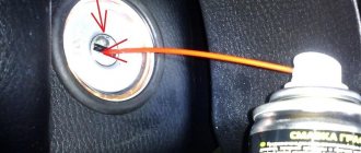
Failures occur due to mechanical wear or loss of contact. The check is carried out by turning the key. If it begins to jam, then as a temporary solution it is possible to use silicone grease by dripping it inside.
In order for the wiring diagram to function correctly, you need to know which contacts to connect to each other. Typically the following wiring system is used:
- red connects to the cable from the starter;
- the pink wire goes to “+” from the 12 V battery;
- brown +12 V is used to start the ignition relay;
- white – relay on;
- black and blue connect other consumers.
It is necessary to check the contacts for the presence of carbon deposits or the possibility of oxidation. Burning contacts can be heard in the cabin by the characteristic smell of burnt insulation.
Voltage is supplied to the electrical power circuits of consumers of the electrical equipment of the VAZ 21093 car through the ignition switch (lock).
Let's consider the order of connecting the wires to the ignition switch, the pinout of the ignition switch terminals and the purpose of each wire (to which circuit it supplies voltage).
For current unloading of the ignition switch contacts, an ignition relay 113.4737-10 is included in its circuit, which is mounted next to it under the instrument panel.
Wires of the ignition switch of a VAZ 21093 car - connection order, pinout of contacts
Ignition key position: “O” (off)
The lock contacts “30” (pink wire – “plus” from the generator) and “30/1” (brown wire – “plus” from the generator) are energized. No electric current flows into the system.
Key position: “I” (ignition)
Contacts “30” (pink wire) and INT (black wire) are closed. Voltage is supplied through one black wire to the exterior lighting switch, instrument lighting switch, through the other to the steering column switch for briefly turning on the high beam headlights.
Contacts “30/1” (brown “positive” wire) and 15/1 (white wire) are closed. Voltage is supplied to the generator excitation winding, the ignition system, to the windshield wiper, carburetor solenoid valve control unit, turn indicators, reversing lamps, and control devices.
Contacts “30” (pink “positive” wire) and “15/2” (blue wire) are closed. The low and high beam headlights, fog lights, headlight cleaners, rear window cleaner, heated rear window, washer, heater fan, and engine cooling fan on the radiator are turned on.
Key position “II” (starter)
Contacts “30” (pink wire) and “50” (red wire to the starter) are closed.
In addition, “30” and “INT” remain closed, as well as 30/1 (brown wire) and “15/1” (white wire on the ignition relay).
Key position “III” (parking)
“30” and “INT”, “30/1” and “P” are closed (on VAZ 2108, 2109, 21099 cars this contact was used to turn on the parking light, the wire is yellow).
Notes and additions
The following are not powered through the ignition switch: emergency, sound, light alarms, interior lighting, dimensions, brake lights. security alarm. electric door locks (if equipped).
For the VAZ 2109, as well as for all other cars, the ignition switch is one of the most basic elements of electrical equipment. This element consists of a mechanical and electrical part. The mechanical part is responsible for locking the steering wheel when there is no key in the lock, and the electrical part is responsible for supplying voltage to the necessary electrical circuits depending on the selected position.
The ignition switch of the VAZ 2109 is faulty.
The most common problem with the ignition lock is its working out and jamming. If these symptoms occur, you should immediately replace the entire ignition switch, because in case of jamming, you can simply burn the starter and then the repair will cost you the cost of the starter. Another common problem is the failure of the contact group. In this case, several devices fail at once. For example, my low beam headlights, heater, cigarette lighter, and rear window heater immediately stopped working. Replacing the contact group with a new one, everything worked immediately.
Starter solenoid relay
The starter relay is called a pull-in relay. This is due to the principle of its operation - it performs the function of connecting the starting device to the electrical circuit and connecting its armature to the crankshaft. It happens like this: when no current is supplied to the windings of the device, its armature, under the action of the return spring, remains in the forward position. The same spring, through a special fork, holds the Bendix gear, preventing it from engaging with the crankshaft flywheel ring.
By turning the key in the ignition, we supply current to the winding of the device. Under the influence of an electromagnetic field, the armature is fed back (pulled into the housing), closing the starter power contacts. The Bendix gear also moves, engaging with the flywheel. At the same moment, the retracting winding is turned off, and the holding winding comes into play. The force from the starter shaft is transmitted through the gear to the flywheel, causing the crankshaft to rotate until we no longer hold the ignition key in the start position.
What functions does the solenoid relay perform:
- Protects the starter from shorting contacts in the ignition.
- In order to turn off the power to the starter in a situation where the engine is running and the key shows the “starter” mode.
- Provides relief of contacts in the ignition switch.
When the engine starts, voltage from the generator goes to the relay coil. Then the gears of the drive system begin to work, due to which a magnetic field is created. The flywheel of the propulsion system is working. The gear begins its work thanks to the holding winding, while the bolts are closed. When the key is returned to the ignition switch, the winding is de-energized, thus disconnecting the gear and flywheel. This scheme applies to modern cars, including VAZ models.
If the starter makes a loud noise, the pole or starter could be loose. In the first situation, strengthen the fastening by tightening the screw, and in the second, secure the starter. If you disassemble the starter and see that the clutch is starting to slip, then the only thing you need to do is replace the starter drive.
A little theory
The ignition switch must switch, that is, connect contacts that supply power to different electrical circuits. The voltage from the battery is supplied to the “30th” contact of the lock, and sometimes two lines are used: “30/1” and “30/2”. Each line is equipped with a 30 Ampere fuse, hence the well-established name.
30 amp fuse painted green
When turning the key, the "30 pins" are usually connected to the following:
- In the “Parking” position – to the “INT” contact, from which current is supplied to additional equipment;
- “Ignition” – to the “INT” contact, also to contacts “15/1” and “15/2”;
- “Start” – to contact “15/1”, but not to “15/2”, as well as to contact “50”.
From terminal “50” power goes to the starter solenoid relay. The “15th” contact, in turn, feeds the main ignition circuit. And if there is an additional circuit, it will be open when the starter operates.
Let us note once again: when the key is set to the “Start” position, contact “15/2” does not receive a positive potential. This is true for all cars of any model, including the VAZ Nine.
Power-up modes used
At each of the turns, the connection of certain devices is provided. There are markings in a circle in front of the socket indicating the position to which a certain mode corresponds.
Null
To activate this mode, just insert the key into the “secret”. In this case, devices that are directly connected to the battery remain active.
Additional consumers will be put into operation after the larva is rotated at a certain angle. Voltage is supplied to pins 30/1 and 30.
The first is “ignition”
In the first position, the driver can turn on the front lighting, such as the low and high headlights. The tidy and interior light up responsively. The connection diagram for the VAZ-2109 ignition switch is activated during this turn, releasing current to the 30–INT pair.
When there is a connection between terminals 30/1 and 15/1, the rear lights, reversing lights, turn signals are operational, and the generator excitation winding is energized. The XX solenoid valve also receives power.
In this position, contacts 30/1 and 15/2 are closed, which ensures the operation of, in addition to the head light optics, the functioning of the fog lights, the rear window wiper and its heating. The headlight cleaners, heater fan and engine cooling system propeller are connected to this contact.
The second is the “starter”
By moving the key to the current position, the driver does not block the connection of electrical consumers that were started in the previous “ignition” position. This fully applies to both the closed contacts of the pair 30/1 - 15/1, and to the pair 30 - INT.
The main change that the VAZ-2109 ignition switch connection diagram provides in such a situation is the activation of a pair of contacts 30–50. This allows the starter to start.
It is important to know that the key is not held in the “starter” position on its own, but springs back to the previous position automatically as soon as the driver releases the force.
Third – “parking”
At this angle of rotation, consumers started in the “ignition” position and closed contacts 30 – INT remain activated. A closed pair 30/1 - P is also added. It is responsible for the parking lighting.
“Classics”, as well as the “Ninth” family
Fiat engineers, when developing the ignition switch for their 124 model, used two supply lines (“30” and “30/1”). The ignition line was the only one.
Connecting the VAZ-2101 lock terminals 5 terminals on the lock module Connecting the VAZ-2109 ignition switch (color coding)
Another ignition circuit containing contact “15/2” was added during the transition to the “2109” family. It, in turn, is switched using a relay. In different families, only the diagram differs, but not the “behavior” of the car when the key is installed opposite the marks:
- Position 0: everything is off;
- Label 1: ignition and engine operation;
- Mark 2: starting the starter;
- Label 3: “Parking” mode.
To turn off the engine, turn the key to position “0”. The spark plugs lose spark and the engine stops.
The ignition switch module, if we talk about the “classic family”, is equipped with 5 terminals (see Fig. 2). Starting from the “2109” family, this solution is not used. Several wires come out of the lock cylinder and are connected to a remote connector.
The connector layout can be easily identified using the color coding (see diagram above). When carrying out any installation work, remember the following: you must turn off the engine, open the hood and disconnect one of the battery terminals. Usually the negative one is turned off.
How does a contact group work?
The contact group in the car is designed to connect all the electrical circuits of the car and group them. When the driver turns the ignition key, the electrical circuit is closed from the minus terminal, which is located on the battery, to the ignition induction coil. Electric current from the wire system goes to the ignition switch, passes through the contacts on it, after which it is sent to the induction coil and returns to the “plus” terminal. The coil provides high voltage to the spark plug, through which current is supplied, then the key closes the contacts of the ignition circuit, after which the engine starts. After the contacts have closed with each other using the contact group, the key in the lock must be turned to several positions. After this, in position A, when the circuit from the power source distributes the voltage, all electrical appliances will start.
Exactly three switched contacts
One line through which current is supplied, and only one ignition circuit - this solution is typical for all VAZ cars, if we talk about the “2110”, “2170” and later families. Even in Grants, produced since 2012, the additional ignition circuit did not appear. In general, with the transition to the “Ten” family, three “significant” terminals of the lock remained:
- Contact "30";
- Terminal “15” (can be designated as “15/1”);
- Terminal "50".
The ignition switch circuit looks trivial, even if we talk about the Lada 2110.
Ten and its ignition switch, diagram Diagram and connector of the ignition switch of modern models Ignition switch connector Tens
The Tens connector has 8 terminals. And in Priora, as well as in Grant and Kalina, this number is reduced to three (Fig. 2).
Of the 8 terminals available in the VAZ-2110 connector, the 7th and 8th simply duplicate each other. Two more are connected to the button, and another pair of terminals are connected to the lamp.
The lock connector of all VAZ models, starting from “2170”, is equipped with only three contact terminals. And the additional connector, which is equipped with a pair of terminals, is connected to the immobilizer in these cars.
The “3” mark has disappeared from the “Tens” lock cylinder. And until now, VAZ produces just such locks, where the key can be installed in one of the following positions:
The presence of the “Parking” mode, as you can see, is not provided here.
Starter circuit for VAZ 2110, 2111, 2112
Starters of type 57.3708 were installed on VAZ-2110 cars and had the following technical characteristics:
- Rated power 1.55 kW
- Current consumption at maximum power no more than 375 Amperes
- Current consumption in the inhibited state is no more than 700 Amperes
- Current consumption in idle mode no more than 80 Amperes
The connection diagram for the starter for the ten is shown above, here is its explanation:
- battery
- generator
- the starter itself
- egnition lock
| 1 – drive shaft; | 20 – contact bolts; |
| 2 – front cover bushing; | 21 – output of “positive” brushes; |
| 3 – restrictive ring; | 22 – bracket; |
| 4 – gear with the inner ring of the overrunning clutch; | 23 – brush holder; |
| 5 – overrunning clutch roller; | 24 – “positive” brush; |
| 6 – drive shaft support with liner; | 25 – armature shaft; |
| 7 – planetary gear axis; | 26 – tie rod; |
| 8 – gasket; | 27 – back cover with bushing; |
| 9 – lever bracket; | 28 – collector; |
| 10 – drive lever; | 29 – body; |
| 11 – front cover; | 30 – permanent magnet; |
| 12 – relay anchor; | 31 – armature core; |
| 13 – holding winding; | 32 – armature shaft support with liner; |
| 14 – retractor winding; | 33 – planetary gear; |
| 15 – traction relay; | 34 – central (drive) gear; |
| 16 – traction relay rod; | 35 – carrier; |
| 17 – traction relay core; | 36 – gear with internal teeth; |
| 18 – contact plate; | 37 – layering ring; |
| 19 – traction relay cover; | 38 – hub with the outer ring of the overrunning clutch. |
Connecting wires to the starter
Connecting a starter to a VAZ - instructions. Attach the relay in a convenient place (for example, a washer reservoir). Connect the wires to the starter. Then remove the red wire located on the flat terminal of the relay, and you need to make a connection with the connector of the male wire and the wire from the new relay.
Place the wire with a ring terminal for 8 mm on the positive side of the starter and tighten it with a nut. Place the wire of the new “female” type relay onto the contact that was released at the traction relay. This wire will transmit the positive to the coil. Using a clamp, tighten the new wire and the stock one together. Screw a small length of wire from the coil. Now you can turn on the new relay.
Source
Possible malfunctions and ways to eliminate them
The nature of the lock assembly malfunctions on a VAZ 2109 car can also be electrical or mechanical.
The first group includes violations of the integrity of electrical circuits in the switch at a certain position of the key. If there is no contact, then the connected consumers may not work, or the car will not start at all. If there is contact, but the wrong parts of the circuit are closed, this is fraught with a short circuit and thermal damage to the lock. It will begin to melt and a characteristic smell will appear. Depending on the scale of the disaster, the contact group will most likely need to be replaced.
From a mechanical point of view, the core/larva may become stuck in some position. In this case, it will be physically impossible to turn the key in the lock. The only correct repair option is to replace the entire assembly.
To diagnose faults in electrical circuits, you need to stock up on the following tools.
- Multimeter or tester. If it is not available, as an option, you can use a control light operating at 12V voltage.
- A set of screwdrivers and keys for dismantling the lock. Since the only option for repairing mechanical faults is to replace parts that have failed, they will come in handy in this case as well.
Before starting diagnostics, you will have to disconnect the terminal block and ring all contacts in the sequence that corresponds to each of the key positions. For clarity, you should have an electrical diagram of the unit at hand. If the circuit is closed, there will be a resistance indication on the device.
Replacing the lock should begin with de-energizing it. To do this, you will have to loosen the fastening nut and remove the negative terminal of the battery. After this, the protective and decorative casing and the turn/window washer switches are removed. The lock is attached to the steering column using four screws or two screws and a hook latch. It may be difficult to remove due to the screws. In this case, they will have to be cut or drilled, doing everything extremely carefully. The terminal block is disconnected, and the dismantling process can be considered complete.
Assembling a new lock assembly occurs similarly, but in reverse order.