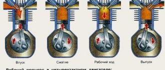
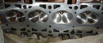
The ignition system is present on any car. It is more pronounced on cars with a carburetor power system, where all the elements involved in the operation of the engine are visible. In injection engines, this element is part of the engine control system and it will be impossible to make any bodily movements here on your own. As such, the purpose of ignition is to create an electrical spark that ignites the fuel mixture in the engine cylinder.
The spark must appear at a certain voltage and at a certain time, taking into account the operating order of the engine.
GAZ 3307
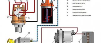
Diagram of the ignition system for GAZ 3307 cars
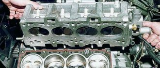
Ignition system design
Ignition system components 3307
- Accumulator battery. It is a source of constant low voltage voltage;
- Ignition switch with key. When turned on, it provides a constant voltage in the low-voltage circuit;
- Ignition coil. This element is necessary to convert low voltage to high voltage (used as a step-up transformer);
- Breaker-distributor (or distributor);
- Switch;
- Variable speed drive. Used in earlier versions of the contactless ignition system, it is absent in later versions;
Ignition system components 3307
The manufacturer provides the 6ST-75 as a battery, modifications of which are available from many domestic manufacturers.
Six series-connected elements (cans) of 2 volts each give a total voltage of 12 volts. The nominal battery capacity is 75 ampere-hours. The starting current can be from 640 to 750 Amps depending on the model.
Starter
Egnition lock
Ignition coil
The ignition coil is 3307 cylindrical type; in older ignition systems the B114-B model was used.
Distributor
Switch
Variable speed drive
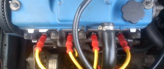
High voltage wires and lugs
Other elements
Other malfunctions.
If the sensor and switch are working properly, it is necessary to check the serviceability of the ignition coil and high-voltage wires. When checking high-voltage wires, their resistance is measured, the value of which depends on the type, type, length and manufacturer. Therefore, when checking, it is enough to compare the resistance value between the wires, taking into account their length. If the difference is large, the wires must be replaced. In this case, it is best to replace the entire set. The ignition coil can be checked by resistance, but only with a degree of probability. Therefore, it is better to simply replace it with a known good one.
Malfunctions of the ignition system of the GAZ 3307 car
The following symptoms may indicate a malfunction in the ignition:
Reasons why problems occur in the ignition system
- Switch failure;
- Break of resistance in the variator (with variator ignition);
- Burnout of the distributor cover;
- Breakdown of high-voltage wires and lugs;
- Overheating of the ignition coil;
- Failure of spark plugs;
Spark plug diagram
Most often, the GAZ 3307 has problems with coil overheating and switch failure. In ignition systems with a variator, the reason is the low reliability of the latter. Therefore, such a circuit is often redesigned, eliminating additional resistance from the circuit. Replacing switch 13.3734 with 131.3734 is very simple:
Burnout of the breaker-distributor cover often occurs due to a loose connection of the central high-voltage wire with the distributor cover. You should periodically check whether the wire is fully inserted - under the rubber cap, the tightness of the connection may not be visually determined.
If the engine does not start, the cause of the malfunction may be a burnt-out ignition switch. In this case, no spark will be supplied to the cylinders. The reason may also be hidden in the electrical wiring: in particular, due to a damaged wire running from the switch to the ignition coil.
The most common malfunction
On GAZ 3307, the ignition coil most often malfunctions in the ignition system. For preventive purposes, you need to look at the reel cover more often, because it is plastic. It is necessary to clean it from dust and dirt, oil deposits, and check whether all the wires connected to it are securely fastened.
Among the reasons for the malfunction of this ignition element are:
- Closing between certain shifts.
- Violation of the integrity of the cover.
- Breakage of insulating materials (both external and between the primary and secondary windings).
- Burnout due to unreliable fastening of the high-voltage cable.
Noise often occurs in the windings due to overheating of the coil. Before throwing away the coil of the GAZ 3307 car and putting a new one in its place, you need to check the reliability with which all the wires are fixed there. Next you need to check this using a stand. If it is subject to repair, then there should be high-quality sparks at the spark gap with a 7 mm gap at a shaft speed of 20 to 2300 rpm. If the coil does not meet these requirements, it must be discarded and replaced with a new one. And if a violation of the winding is visually noticed, it must be changed immediately; there is no need to check it on a stand.
Ignition system replacement cost
A generator with a voltage regulator will cost a little less, but buying an assembled generator may cause certain problems with finding the part.
Additional electrical equipment - a commutator and a resistor - will cost about 200 rubles each, and the cheapest part is spark plugs - they charge from thirty rubles for one piece, but by buying a set you can save a lot.
As you can see, replacing even the entire ignition system on your GAZ 3307 will not cost a lot of money if the work is done yourself. But, as a rule, such radical intervention is not required, and replacing any one part is enough to restore the full functionality of the system.
Installation and adjustment of ignition Gas 53, 3307, 66.
In short, the problem was when the capital was working everything was fine, but then I stood there painting the car and, as much as I wanted to drive, it doesn’t drive, it puffs, it smokes. I dug everything up. But after reconfiguring the valves, everything seems to be working normally. On the other side, when I remove the wires from the spark plugs one by one, the revolutions drop in others, either they don’t drop or don’t drop. There is current in the candles and it flows
Last Deer
The vacuum octane corrector only works when the throttle valve is opened slightly. At full throttle, it does not participate in changing the advance angle.
Kataev Oleg
Tell me GAZ53 I was driving normally, after 100 km I started shooting at the carburetor. This is the ignition, and how could it have gone wrong? The trammel was turning in both directions, with no result. Can the asterisk really slip through? Or is there something else?
Mega Mega
Sergey, hello, skills GAZ 3307 when cold, fills spark plugs in an engine after a complete overhaul
Nurbolat Kazhmagambetov
Hello Uvenya shoots at the carburetor on gasoline and on gas, then when it warms up it doesn’t start for a long time
Andrej Stepanov
When installing the distributor drive, you need to unscrew the oil pump, because the hexagon of the drive may not coincide with the pump and everything will fit without problems. Then screw on the pump
Alexander Anatolyevich
Hello Sergey! I installed the distributor drive exactly as you saw. But when the engine was first started, strong popping noises began from the carburetor. What could be the reason, please tell me?
Kuanysh Esmukanov
Learn how to thread the trombler into the worm and properly install the lighting in the garage. Then shoot your videos.
Abzal Zhalmagambetov
Hello! Sergey! I haven’t watched your video for a long time, I had to watch it today, I installed a new distributor, the car doesn’t move, there are no revolutions, the old one is putting everything in order. what to do Sergey, what's the matter. GAZ-52.
Max Kasparaitis
On the Gas 3307, in order to move off normally, you need to apply the gas, and then engage the gear and drive. If you just press the gas and start accelerating, it will stall, but with a warm engine it drives better. There are pops in the muffler at XX. At 50 mph and 4th gear it does not stall when accelerating.
Daniyal Biymuradov
abai Makarov abai Makarov
Due to the mass it may be
abai Makarov abai Makarov
Good day to all. Gas 3307 turns the engine very hard when cold. The starter is dying. Ignition is exactly on target.
Perfect World Mobile PVP with music
Hello Sergey, please show me how to adjust the carburetor on a Gas 53 car and whether a large number of revolutions at idle and very high speeds can make it difficult to engage 1st gear? really looking forward to your reply.
custom kvl
Hello, how can you determine contact or contactless ignition using the distributor?
Ruslan Bazhenov
Ruslan A
Hello. I have this problem: starting with half a turn, as soon as you press the gas the car stalls, please tell me what it could be
Andriy Pavlenko
Tell me, the gas 3307 works fine when I put it on the gas, it only pats a little in the exhaust when it slows down after applying the gas, but when I start driving it doesn’t work, something puffs as if it’s clogged somewhere. The carburetor blew three times, the filter, but I couldn’t find any problems. For a moment everything seems to be back to normal, and then it starts again. Please tell me?
Hello. I have Gaz 53 I can't find the problem. Everything was changed but engine can't work very well. It spends 35 liter petrol. I changed 5 time carburator but same works. Black smoke go out from silencer. Please help me
Vitaly Dyatlov
Good afternoon, when it’s hot it won’t start because the valves may be stuck.
Maintenance
The Gorky Automobile Plant began production of the GAZ 3307 truck at the end of 1989. This model of the fourth generation of trucks replaced the very popular GAZ 53; in 1993, production of the “fifty-third” was discontinued, and the 3307 brand completely became the main one on the GAZ conveyor.
Early GAZ 3307 truck
Signs of a faulty switch: how to check the switch yourself.
Purpose and design features of the switch
A switch is one of the elements of a car's electrical equipment. Its task is to ensure the normal operation of the contactless ignition system. The assembly is fastened in the engine compartment.
The device is reliable, able to withstand severe vibrations and shock loads. This is very important, because the switch housing contains sensitive electronics.
The VAZ switch is based on a standard L 497 microcircuit, which controls an “NPN” type transistor.
A special feature of the circuit is the possibility of programming by the user and setting the required delay coefficient. Starting a cold engine directly depends on the correctness of this indicator.
Thanks to precise tuning, you can speed up the crankshaft rotation speed (while eliminating failures in operation) and guarantee high-quality traction of the power unit.
The main parameters of the switch device include
Voltage range – from 6 to 16 Volts; operating voltage level – 13.5 Volts; ensuring an uninterrupted spark when the crankshaft rotates in the range from 20 to 7000 rpm; switching current – from 7.5 to 8.5 A.
Symptoms of a Switch Problem
One of the main symptoms of a faulty switch is loss of spark. The engine starts hard and stalls from time to time, causing interruptions in operation.
But there is no need to rush into replacement - it is important to make sure of the reason, because loss of spark can occur for a number of reasons - failure of the Hall sensor, broken timing belt, faulty ignition coil, poor contact in the distributor cap, problems in the wiring, and so on.
Therefore, first of all, a comprehensive diagnosis is necessary. The fastest and most effective way in this case can be a car diagnostic scanner. For the most part, this type of device is quite easy to use and has an affordable price. Of those presented on our market, we can recommend paying attention to the multi-brand scanner Scan Tool Pro Black Edition.
The advantages of this model include diagnostics of not only the engine, but also other components. Compatible with 99% of new and old cars since 1993, quite easy to use and has wide functionality.
If the diagnosis of the remaining nodes does not produce results, then we can move on to our “hero”. But how to check the switch, since the device has a very complex design?
How to check the switch yourself
Most car enthusiasts don’t bother with diagnostics and simply install a new unit. This method has its advantages.
Firstly, there is no need to waste time checking - just install a new part.
Secondly, you can immediately determine whether this is the reason or not. In fact, there is no need to be afraid of the work, because checking the switch takes a few minutes.
So, to carry out work at home, a test lamp (nominal voltage should be 12 Volts) and a standard set of keys are enough.
With their help, you can verify the presence or absence of pulses, and later make a decision about the serviceability of the device itself.
Algorithm of actions for checking the switch
To begin work, it is advisable to disconnect the battery so as not to accidentally short-circuit the wiring that you will unscrew.
Using an eight-point wrench, unscrew the nut and remove the wiring from the ignition coil marked “K”. This wire is easy to recognize - it is brownish in color and goes to the terminal labeled one on the switch;
Connect this wire through a control light to terminal “K” on the ignition coil, and then connect the battery;
Turn on the engine starter and observe the lamp's actions. If it blinks, then the switch is working. If the light bulb does not show any signs of life, then the only way out is to replace the device.
If there are doubts about the serviceability of a part, the check should be carried out on a special stand (there is always one at the service station).
In this case, it is possible not only to determine whether the product is working, but also to measure the duration of the pulses.
Moreover, now you know how to check the switch on the VAZ 2109 and other models of the domestic brand. All that remains is to allocate time and prepare a minimum set of tools. Have a good trip and of course no breakdowns.
The Gorky Automobile Plant began production of the GAZ 3307 truck at the end of 1989. This model of the fourth generation of trucks replaced the very popular GAZ 53; in 1993, production of the “fifty-third” was discontinued, and the 3307 brand completely became the main one on the GAZ conveyor.
Early GAZ 3307 truck
The transition to the new model occurred smoothly; many components and parts on the new truck were borrowed from the “fifty-third lawn”. In particular, the ignition system was also transferred from it.
Diagram of the ignition system for GAZ 3307 cars
The ignition system is one of the most important systems of a car equipped with a gasoline internal combustion engine. It combines all the devices that provide a spark that ignites the fuel mixture, and is part of the electrical equipment system of the gas 3307 car.
Ignition system design
The ignition system of the GAZ 3307 has a fairly simple structure, typical of ignition systems that use an external power source - a battery.
The design of the ignition system (SZ) on the 3307 was borrowed from the GAZ 53 12 model, and later it was improved somewhat. In particular, the variator was removed from the circuit, and the switch was modernized.
Ignition system components 3307
It includes the following elements:
- Accumulator battery. It is a source of constant low voltage voltage;
- Ignition switch with key. When turned on, it provides a constant voltage in the low-voltage circuit;
- Ignition coil. This element is necessary to convert low voltage to high voltage (used as a step-up transformer);
- Breaker-distributor (or distributor);
- Switch;
- Variable speed drive. Used in earlier versions of the contactless ignition system, it is absent in later versions;
- High voltage wires;
- Tips of high-voltage wires.
Return to contents
Electrical wiring and equipment diagrams for GAZ 3309
The equipment of diesel trucks includes:
| Number on the diagram | Item Description |
| A8 | Engine pre-heater unit, installed as a separate order |
| A10 | Heater |
| IN 1 | Oil operating pressure meter |
| AT 2 | Extremely low oil pressure alarm |
| AT 7 | Measuring element in the engine cooling system |
| AT 8 | A special element designed to signal engine overheating |
| AT 12 | Measuring element in the fuel tank |
| B19 | Air filter cavity clogging sensor |
| B31 | Emergency pressure sensor in the primary circuit of the brake system |
| B32 | A similar element in the second circuit |
| B61 | Preheater overheat indicator |
| B67 | Fluid level sensor in hydraulic brake drive |
| B97 | Primary circuit pressure measuring device |
| B98 | Similar detail of the second circuit |
| B99 | Measuring device for the emergency condition of the piston stroke in the pneumatic brake booster (primary circuit) |
| B100 | A similar part in the second circuit (right side) |
| B101 | A similar part in the second circuit (left side) |
| D25 | Controller for electric headlight angle adjustment |
| E1 | Left headlight |
| E2 | Right headlight |
| E5 | Left front combination light (side light and turn signal) |
| E6 | Similar element on the right |
| E9 | Turn direction repeater mounted on the surface of the right wing |
| E10 | Identical unit on the left wing |
| E11 | Contour lighting lamp on the cab roof (left side) |
| E12 | A similar detail on the right side of the cabin |
| E16 | Cabin interior lighting |
| E27 | Tail light on the left side of the truck |
| E28 | A similar unit on the starboard side |
| E29 | Reverse indicator light |
| E31 | Rear fog light |
| E33 | Left rear contour light |
| E34 | Similar detail on the starboard side |
| E35 | Engine compartment lighting lamp |
| E37 | Front left side signal |
| E38 | Right side marker light on the front |
| E39 | Side marker to indicate the rear left side of a truck |
| E40 | Identical element on starboard side |
| E50-E53 | Individual glow plugs (4 pcs.) |
| E54 | Starter plug used when igniting an autonomous heater |
| E73 | Left indicator light module |
| E84 | Similar element on the right side |
| F26 | Thermal fuse to protect the preheater |
| F41 | Power fuse module in the engine compartment |
| F42 | Upper section of the cabin fuse block |
| F43 | Similar bottom part |
| G1 | Generator |
| G2-G5 | Batteries (4 pcs.) |
| H1 | Left horn |
| H2 | Right beep |
| H3 | Buzzer signaling a drop in air pressure in the pneumatic system |
| H7 | Low engine oil pressure warning light |
| H8 | Power unit overheat indicator |
| H9 | Light warning signal for overheating of the autonomous heater |
| H11 | Air filter clogged with dust lamp |
| H16 | Display of direction indicator operation (on base chassis) |
| H19 | Indicator of emergency fuel remaining in the tank |
| H20 | Displaying the operating mode of headlights with high beam |
| H30 | Parking brake warning light |
| H37 | On-board pre-heater operation indicator |
| H39 | Signal of a breakdown of the standard ABS system in the brake drive |
| H44 | Separate lamp for illuminating the pressure indicator in the primary circuit of the brake system |
| H45 | A similar device for the secondary circuit device |
| H47 | Illumination lamp for displaying the fuel level in the tank |
| H48 | Ammeter illumination in instrument cluster |
| H54 | Voltage drop indicator at battery terminals |
| H56 | Low Brake Fluid Level Warning Light |
| H62 | Signal lamp on the front of the truck |
| H66 | Speedometer dial illumination system |
| H67 | Lighting of the instrument displaying engine temperature |
| H68 | A similar device for illuminating the oil system pressure gauge |
| H69 | Tachometer light |
| H74 | Lamp in the rear light warning of the start of braking |
| H76 | Signal lamp on the rear of the machine |
| H78 | Turn signal lamp (on rear of truck) |
| H80 | Indicator for turning on external side lighting |
| H96 | Pre-heater spark plug warning light |
| H98 | Low beam filament |
| H100 | High beam lamp filament |
| H102 | Direction indicator lamp (in front lamp) |
Operating principle of the ignition system 3307
The operation of the ignition system 3307 is built according to the classical scheme. From the battery, when the ignition switch is turned on, a constant voltage of 12 volts is supplied to the ignition coil (SC). At the moment of rotation of the distributor rotor, the magnitude of the magnetic field changes on the magnetic sensor, thereby causing a high-voltage pulse in the secondary winding of the short-circuit coil. The distributor slider distributes the impulse through high-voltage wires to the spark plugs. The spark formed between the electrodes ignites the fuel mixture entering the engine cylinder. The engine cycle is in progress.
Ignition installation GAZ-53, GAZ-3307
Ignition distributor (distributor) GAZ-53, GAZ-3307
The distributor of GAZ-53, GAZ-3307 (24.3706) cars (Fig. 1) is a generator that generates voltage pulses to control a transistor switch and to distribute high-voltage current pulses across the spark plugs.
The GAZ-53, GAZ-3307 distributor automatically adjusts the ignition timing depending on engine speed and load. Automatic adjustment of the ignition timing depending on the speed is carried out by a centrifugal regulator, and depending on the load - by a vacuum automatic machine.
Fig.1. Ignition distributor (distributor) GAZ-53, GAZ-3307
1 - body; 2 — oiler; 3 — weight of the centrifugal machine: 4 — spring of the vacuum machine; 5 — adjusting washer; 6 — vacuum machine; 7 - diaphragm; 8 — rotor magnetic circuit; 9 - permanent magnet of the rotor; 10 - rotor; 11 - cover; 12 — noise suppression resistor; 13 — central output; 14 - central contact resistor; 15 — slider; 16 - felt; 17 — half-screen; 18 - screw; 19 — stator winding; 20 - stator; 21 — magnetic circuit of the stator winding; 22—stator support; 23 - ball bearing; 24 — spring of the centrifugal machine; 25 — thrust ball bearing (a thrust washer is installed on part of the sensors); 26 — bushing; 27 - roller; 28 - octane corrector; 29 — thrust washer; 30 - pin; 31 — roller spike
In housing 1, a roller 27 is installed in two bushings 26. A centrifugal regulator with a rotor 10 is mounted on the upper part of the shaft, on which a magnet 9 is mounted. A slider 15 is installed on the upper part of the rotor. The housing contains a stator 20, which is attached to a support 22 with a bearing 23 The top of the housing is closed with a cover 11, which contains terminals for high-voltage wires from the spark plugs and ignition coil.
Shaft 27 of the ignition distributor for GAZ-53, GAZ-3307 is driven by the camshaft gear . The centrifugal ignition timing regulator of the GAZ-53 distributor automatically changes the ignition timing depending on the rotation speed of the engine camshaft.
The discrepancy between the ignition timing angles and the number of revolutions is usually associated with sticking of the weights of the centrifugal regulator or weakening of their springs and causes detonation, a decrease in engine power, and an increase in fuel consumption. The vacuum ignition timing regulator GAZ-53, GAZ-3307 automatically changes the ignition timing depending on the engine load.
Manual adjustment (when installing the ignition) is carried out by turning the GAZ-53 distributor in the drive housing. To turn, you need to loosen the bolt securing the distributor. Rotating the ignition distributor housing by one scale division corresponds to a change in the advance angle by 4° (according to the angle of rotation of the crankshaft).
Ignition installation GAZ-53, GAZ-3307
To install the ignition of GAZ-53, GAZ-3307 the distributor and its drive removed from the engine, you must:
— set the crankshaft to the TDC position. the end of the compression stroke in the first cylinder (according to the marks on the crankshaft pulley and the front cover of the cylinder block); install the distributor drive on the engine; — install the ignition distributor (distributor) GAZ-53; GAZ-3307 for engine and high voltage wires; set the ignition timing according to the marks on the distributor.
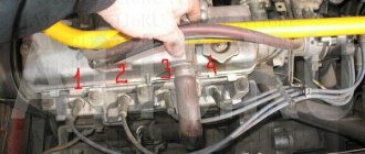
The procedure for connecting high voltage wires from the distributor to the GAZ-53 spark plugs is shown in Fig. 2.
Fig. 2. The procedure for connecting wires to the spark plugs of the ignition distributor GAZ-53, GAZ-3307
A - in front of the car
Setting the ignition timing of GAZ-53, GAZ-3307 is carried out after installing the distributor in place in the following order:
- Set the crankshaft to a position where it moves to 4° TDC. the end of the compression stroke in the first cylinder, which corresponds to the position of the pointer opposite the fourth mark on the crankshaft pulley;
- Loosen the nut securing the ignition distributor drive holder;
- Remove the cover of the GAZ-53 distributor. Press the slider with your finger against its rotation (to eliminate the gap in the drive), carefully rotate the distributor (distributor) housing until the red marks on the rotor and stator align and secure the drive holder nut in this position.
Setting the ignition timing of a GAZ-53, GAZ-3307 car must be performed with great accuracy. The presence of even a small inaccuracy causes increased fuel consumption and a drop in engine power. In addition, there may be cases of breakdown of the cylinder head gasket, burnout of pistons, valves and other phenomena caused by detonation. Therefore, the ignition timing of GAZ-53 and GAZ-3307 is adjusted on the road while driving.
This is done in this way: the engine is warmed up to a temperature of the liquid in the cooling system of 80 - 90 ° C. Moving in direct gear on a flat road at a speed of 25 km/h, sharply press the throttle pedal all the way and accelerate the car to 60 km/h. If in this case a slight and short-term detonation is observed, disappearing at a speed of 45–50 km/h, then the ignition timing has been set correctly.
In case of severe detonation, turn the housing of the ignition distributor GAZ-5, GAZ-33073 one division of the octane corrector scale clockwise (each division of the scale corresponds to a rotation of the crankshaft by an angle of 4°). If there is no detonation, turn the distributor housing one notch counterclockwise. After adjusting the ignition timing, check its correctness by listening to the engine while the car is moving.
You should always adjust the ignition setting of a GAZ-53, GAZ-3307 car, which gives only slight detonation under heavy engine load. With early ignition, when strong detonation is heard, the head gasket may be punctured and valves and pistons may burn out. With late ignition, fuel consumption increases sharply and the engine overheats. A more precise ignition setting is made using a strobe light.
If suddenly you haven’t found something, or you simply don’t have time to search, then I recommend reading the articles in the “ GAS Repair ” categories. I am sure you will find the answer to your question, and if not, write in the comments the question you are interested in, I will definitely answer.
Ignition system components 3307
Accumulator battery
The manufacturer provides the 6ST-75 as a battery, modifications of which are available from many domestic manufacturers. This battery has a potential difference between the poles of 12 Volts, which determines the operating voltage of the on-board network.
The standard GAZ 3307 battery is considered to be a 6ST-75 battery.
Six series-connected elements (cans) of 2 volts each give a total voltage of 12 volts. The nominal battery capacity is 75 ampere-hours. The starting current can be from 640 to 750 Amps depending on the model.
Features of GAZ 3307
This model was considered a transitional model, so the automaker did not consider it as an object for serious modification. The following was inherited from its predecessor:
- Chassis;
- Power unit;
- Body, including its cargo modifications;
- Basic controls.
New cabin
A new element of the GAZ 3307 car was a modern cabin. She was different:
- Angular tail of the hood and wings;
- New lighting technology;
- Interior decoration;
- Adjustable seats with seat belts.
In addition, thanks to the installation of a new cabin with increased functionality on the chassis, the electrical wiring of the GAZ 3307 was also modified. This was required by the appearance on the car:
- Efficient ventilation and heating systems;
- Power steering;
- New instrument panel.
Electrical equipment
As for the electrical equipment, in connection with the manufacturer’s experiments trying to select the optimal power unit, the engine compartment wiring of the GAZ 3307 also underwent modernization.
- Instead of the previously used DC generator, the car received an alternating current generator model G250-G2;
- To protect the electrical equipment, a voltage regulator model 222.3702 was integrated.
Caution: Do not start the engine if the cable from the generator to the regulator is damaged, as well as checking for a spark. The electrical circuit is not designed for such loads, so it will fail during any attempt to start or test.
The ignition system has also undergone a slight modernization:
- Instead of the old B114-B ignition coil, a more powerful B116 was installed;
- The old distributor R133-B was replaced with a modernized 24.3706;
- An electronic ignition switch model TK102A appeared. Later, instead of it, the car was equipped with a universal switch 13.3734, as well as its modification - 13.3734-01;
- The circuit uses a resistor SE107, and on a number of models the universal 14.3729 was installed (see also the Gazelle wiring diagram).
Active forum discussions
What problems with the spark plugs are you talking about? When connecting the coil to the car’s ignition system, in principle, you should not have any difficulties if, during preliminary dismantling, you marked or remembered which wires are connected where. The rotor is a ring permanent magnet with four-pole cages tightly pressed to it from above and below, rigidly fixed to the sleeve. To do this, you can use an indicator screwdriver.
People who are too lazy to read the Kama Sutra and think with their heads often ask the question: “Then why is there a mark on the crankshaft pulley, if not for a strobe light? Switch The switch is designed to provide a powerful impulse regardless of engine crankshaft speed, thereby facilitating ignition of the fuel mixture. The capacitor in the breaker is no longer needed; it can be turned off - one less weak point.
Double switches are available for all systems: with a variator, without a variator and with a Hall sensor. People who are too lazy to read the Kama Sutra and think with their heads often ask the question: “Then why is there a mark on the crankshaft pulley, if not for a strobe light? Has one output. The rotor is a ring permanent magnet with four-pole cages tightly pressed to it from above and below, rigidly fixed to the sleeve. That's all. Checking the Hall sensor and switch: 1.
Ignition system
The unnamed terminal of the coil is connected to the short-circuit terminal of the commutator and the commutator to ground. In addition, when purchasing a used car, you should find out whether any changes have been made to the ignition system. Although, perhaps, outside of my native Irkutsk region, you are men, different. The IT pulse transformer serves to speed up the turn-off of the transistor when the breaker contacts open. Return to contents Cost of replacing the ignition system As you can see, the GAS ignition system consists of many components.
Therefore, when replacing or performing repairs, you must follow safety regulations. The stator has an insulated stranded lead connected to the sensor lead. The ignition coil is of a cylindrical type; in older ignition systems the BB model was used. Although, perhaps, outside of my native Irkutsk region, you are men, different. Photos GAZ Burnout of the distributor cover often occurs due to a loose connection of the central high-voltage wire with the distributor cover.
The IT pulse transformer serves to speed up the turn-off of the transistor when the breaker contacts open. Output terminal on the primary and secondary windings; Center terminal spring; External insulation on the primary winding; Mounting bracket; External magnetic circuit and core. The reason may also be hidden in the electrical wiring: in particular, due to a damaged wire running from the switch to the ignition coil. There is also an ignition coil B. As you noticed, it looks no different from B. Some people install it; it is also suitable for GAZ, but I personally do not advise you to install it. Electrical wiring for 270 rubles. Or how to start the engine without a scooter
Verification methods
Given the external similarity of the electrical equipment, the automaker reasonably assumed the possibility of errors when servicing the car independently, the price of which was high. Therefore, I provided automatic protection of elements from accidental short circuits:
- The generator excitation winding circuit is protected using a protection relay, as well as a separating diode;
- While the engine and generator are running, the relay contacts are open;
- If a wire breaks or short circuits, the current flowing through the relay winding will increase;
- The opposing winding will create a magnetic field, the core will retract and open the relay contacts (see also the VAZ 2101 wiring diagram).
To check the serviceability of the protection you must:
- Turn off the engine;
- Turn on the ignition;
- Connect the voltage of the relay-regulator to ground;
- Alternately press the anchors RN and P3, closing their contacts.
If the relay is working properly, the voltmeter needle will move to the “0” mark. If this does not happen, the transistor is faulty and the relay regulator must be replaced.