The catalog of materials for repairing VAZ 2101, 2103 or 2106 will allow visitors to the etlib.ru portal to repair a broken car part on their own. This collection of instructions is a modern guide to vehicle maintenance , repair and operation. The instructions presented in the form of videos will be an excellent tool, which will demonstrate with a clear example each action of the technician during troubleshooting.
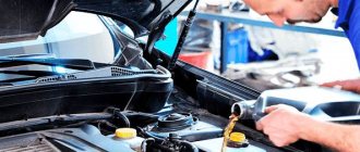
In addition to video tutorials, the site also contains other materials. They contain no less valuable information for those who want to repair a VAZ 2101 with their own hands or any other of the above models. The instructions are supplemented with photographs taken during the repair work. They will make it easier for even inexperienced drivers to understand the algorithm of actions.
There are a number of procedures that are most often looking for . Using one of the manuals, you can replace the valves of a VAZ 2101 yourself. For drivers who decide to repair a VAZ 2103 with their own hands, the material that details The replacement of the VAZ 2103 timing chain is described.
As for VAZ 2106 drivers, they need the VAZ 2106 repair manual most of all. Owners are interested in replacing the VAZ 2106 generator, replacing the VAZ 2106 clutch and replacing the VAZ 2106 pads. All these procedures allow you to restore the car’s performance in the event of a sudden breakdown. A little less often, you may need to replace the VAZ 2106 stove, as well as replace the VAZ 2106 oil seals.
If there is no specific information on the site pages. It can always be obtained from other visitors. Experienced motorists will help with advice and tell you how to make repairs for a VAZ 2106 yourself without negative consequences.
Historical information – VAZ 2101
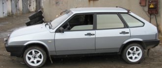
The Soviet rear-wheel drive car was first assembled in 1970. He became the founder of a whole family, which continued to be produced until 2012.
The VAZ 2101 was presented in a sedan body with a 4-speed gearbox and two types of engines 1.2 and 1.3 liters (the latter for the updated version of the VAZ 21011).
For owners of the VAZ 2101 model, maintenance and repairs were cheaper than foreign cars, which made the car popular in the domestic market.
Accessory drive
The engine auxiliary components, as well as the valve train, are driven from the crankshaft using a chain drive, which is located in the front cavity of the cylinder block and is closed by an aluminum cover.
The chain drive consists of a double-row bush-roller chain 44, a drive sprocket 53 mounted on the crankshaft, a driven sprocket 45, a driven camshaft sprocket 42, a chain damper 43 and a tensioner 30 with a shoe 46.
The tensioner shoe and chain guide have a steel frame with a vulcanized rubber layer. A limit pin 54 is installed in the lower part of the cylinder block, which prevents the chain from falling into the engine crankcase when removing the camshaft sprocket (when the cylinder head on the car is removed).
The drive shaft 47 of the oil pump and ignition distributor is mounted along the engine and has two support journals, a helical gear and an eccentric 52, which drives the fuel pump through a pusher. The roller helical gear 47 meshes with gear 49 and drives the ignition distributor and the oil pump. Gear 49 is installed vertically and rotates in a cermet bushing 50, pressed into the cylinder block. The gear has a splined hole into which the splined ends of the ignition distributor and oil pump rollers fit.
The ignition distributor housing is installed on the upper plane of the cylinder block and is attached to it with a steel plate. The oil pump is bolted to the bottom plane of the cylinder block.
Historical information – VAZ 2106
VAZ 2106 is a modernized version of the VAZ 2103, which appeared in 1975 and continued to be produced until 2005. Among the features, it is worth highlighting minor changes to the exterior , the ability to choose a 4 or 5-speed gearbox, as well as a 1.6 liter engine with a power of 76 hp.
In total, VAZ 2106 engines were built in the following line:
- VAZ-2106 - petrol 8-valve 1.6.
- VAZ-2103 - petrol 8-valve 1.5.
- VAZ-21011 - petrol 8-valve 1.3.
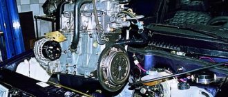
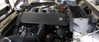
General structure of a car engine
The cars are equipped with four-cylinder, four-stroke carburetor engines with different cylinder capacities.
The engine layout is simple and easy to maintain. All engine components that require adjustment or maintenance (ignition distributor, spark plugs, carburetor, air filter, valve lever adjusting screws, chain tensioner nut, oil filter, generator) are installed in easily accessible places.
The engine cylinders are combined with the upper part of the crankcase and form a single casting - the cylinder block. This arrangement ensures structural strength, rigidity, compactness, reliability and reduces engine weight. Each engine cylinder has one intake and one exhaust valve.
Pistons 17 have two compression rings 40 and 41 and one oil scraper ring 39 with a spring. The piston and connecting rod 11 are connected by a piston pin 16, pressed into the upper head of the connecting rod.
The camshaft 23 is mounted on the cylinder head in the housing 24 and is driven by a double-row roller chain 18 from the crankshaft. The advantages of the drive are simplicity of design and lower weight compared to other types of transmissions.
Cylinder block 12 is the basic part of the engine and is used for installing and fastening mechanisms, devices and auxiliary units of the engine. The block is cast from special low-alloy cast iron. Coolant passages are made along the entire height of the cylinders, which improves cooling of the pistons and piston rings and reduces block deformation from uneven heating.
To increase engine rigidity, the lower plane of the block is lowered 50 mm below the axis of the crankshaft. The block cylinders are divided into five classes by diameter, every 0.01 mm, designated by the letters A, B, C, D, E. The cylinder class is indicated on the bottom plane of the block opposite each cylinder. The cylinder and the piston mating to it must have the same class. When repairing a block, the cylinders can be bored and honed to accommodate an increased piston diameter (by 0.2-0.4-0.6 mm), taking into account the provision of a gap between the piston and the cylinder equal to 0.05-0.07 mm.
At the bottom of the cylinder block there are five supports of the crankshaft main bearings with thin-walled steel-aluminum liners 4. The bearings have removable covers 2, which are attached to the block with self-locking bolts. The holes for the crankshaft bearings in the cylinder block are processed together with covers. Therefore, bearing caps are not interchangeable and have risks on the outer surface for differences. The bearing supports and their corresponding caps are measured from the front end of the cylinder block.
On the left side of the block there is a drive shaft for the oil pump, ignition distributor and fuel pump. Rolled steel-aluminum bushings are pressed into the holes for the roller bearings. By processing them together in the block, the necessary alignment of the bearings is ensured. When checking the technical condition and repairing the block, it is necessary to ensure that the lubrication hole in the front bushing coincides with the channel in the cylinder block.
In the front part of the cylinder block there is a cavity for the chain drive of the gas distribution mechanism. This cavity is closed with a cover 14. A rear oil seal holder is attached to the rear side of the cylinder block. Self-clamping seals are installed in the cover 14 and the holder.
On the left side, an oil filter, a fuel pump are attached to the cylinder block, a crankcase ventilation system and an electric oil pressure sensor 33 are installed. The engine of the VAZ-2103 car is equipped with an additional sensor 32 oil pressure indicator. A water pump and generator are installed on the right side of the cylinder block. At the bottom of the cylinder block on the right and left sides there are bosses for installing the engine on the suspension brackets. A breaker-distributor is installed on the upper plane of the block in its front left part. The bottom of the cylinder block is closed with a stamped steel crankcase 38. The crankcase has a baffle to calm the oil. A cork rubber gasket is installed between the oil pan and the cylinder block.
Cylinder head 19 is common to four cylinders, cast from aluminum alloy, and has wedge-shaped combustion chambers. Valve guides and seats made of cast iron are pressed into the head. The intake valve seat dimensions are larger than the exhaust valve seat dimensions. Between the head and the cylinder block there is a gasket made of asbestos material on a metal frame, impregnated with graphite; The gasket has a mild steel surround around the edges of the cylinder bores. The hole in the oil supply channel to the camshaft is edged with copper tape. To prevent the gasket from sticking to the block and cylinder head, it is recommended to rub it with graphite powder before assembly.
Why does the body rot?
- In the 70s and 80s, the thickness of the metal of body parts was 0.8 mm; closer to the 90s, this parameter often reached a value of 0.5 mm, although, as the official operating instructions stated: “... the thickness of the metal is equal to 0.7 mm...";
- The hinged elements (doors, hood, fenders) have a sophisticated design, with many hidden openings and cavities of unknown purpose. They are the initial sources of corrosion;
- Winter operation in urban conditions is also fraught with the negative impact of road reagents;
- Cheap car tuning. Yes, yes, it’s all these extra-studded hangers - linings that accumulate dirt and moisture underneath;
- Garage-free storage. Sharp temperature fluctuations cause condensation to appear on body parts, which in turn do not have time to dry out and are constantly in a wet state;
- The car is rarely washed and cleaned of dirt, which likes to accumulate in various niches and cavities.
Lesions
Areas susceptible to body corrosion
As time has shown, in most passenger cars, corrosion damages certain areas of the body, the number of which is not so large. But corrosion develops especially actively in hard-to-reach places - gaps, flanges, bends of edges, that is, where moisture does not evaporate for a long time:
- Wheel arches are not only constantly exposed to aggressive environmental influences, they are also damaged by road surface particles flying from the wheels, which accelerate the corrosion process;
- Thresholds, doors, fenders, hood and trunk lids are an excellent place for the accumulation of moisture, penetrating both from the outside and in the form of condensation;
- In places where parts rub against each other (at places where hinged parts are attached, doorways, etc.).
Attention! If corrosion has spread to the central pillars, the joint of the sub-engine frame, side members and other strength elements, then it would be wiser to replace the body completely, since in this case welding the frame is not practical and is a complex process that only trained professionals can do.
The corrosion process can be divided into two types:
- Surface (the process occurs evenly over the surface of the part).
- Point (the process of corrosion goes into the thickness of the metal - cavities, holes, stains).
Surface corrosion
Surface corrosion
This type of corrosion at the initial stage (until it turns into the second type) is not terrible and most often occurs due to poor preparation of the part for painting. We will not consider this type of repair in this article; we will only mention that it is not complicated and does not require special skills. It can be treated by re-cleaning the part, degreasing, priming and painting. I promise that in the future I will provide detailed video and photo instructions, but for now let’s move on to the second type.
Pitting corrosion
Pitting corrosion
Here it is - the first enemy of the car, which destroys the part, destroying not only its surface, but also making the metal structure so fragile that operating the car becomes simply a dangerous activity. Here, treatment will require more serious plumbing skills, or at least the desire to acquire them. After all, it’s not the gods who burn the pots, is it?
Advice! If the metal is heated in the flame of a gas burner to a light red glow and does not crumble into a sparkling fountain or evaporate, then it is quite suitable for welding work.
Maintenance
| Maintenance object | Time or mileage (whichever comes first) |
| Valve train chain | replacement after 100,000 km |
| Battery | 1 year/20000 |
| Valve clearance | 2 years/20000 |
| Crankcase ventilation | 2 years/20000 |
| Belts that drive attachments | 2 years/20000 |
| Fuel line and tank cap | 2 years/40000 |
| Motor oil | 1 year/10000 |
| Oil filter | 1 year/10000 |
| Air filter | 1 – 2 years/40000 |
| Fuel filter | 4 years/40000 |
| Heating/Cooling Fittings and Hoses | 2 years/40000 |
| Coolant | 2 years/40000 |
| Oxygen sensor | 100000 |
| Spark plug | 1 – 2 years/20000 |
| Exhaust manifold | 1 year |
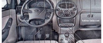
Wiring harness in the cabin
The front wiring harness, located in the engine compartment, is the main electrical system. The front beam enters the car interior through a technological hole with a seal under the instrument panel. The front end electrical system connects to the dash wires, fuse box, switches, and ignition. In this part of the cabin, the main electrical circuits are protected by fuses.
The new cable will provide sufficient voltage to power current consumers in the cabin
The fuse box is located to the left of the steering wheel. Auxiliary relays are attached to the bracket behind the block. The reliable operation of the VAZ 2101 depends on the proper functioning of electrical devices and relays. Fuses protect the electrical circuits of the VAZ 2101 from short circuits.
Simple fuses are a reliable safety element in the event of a short circuit
List of electrical components protected by fuses:
- Horn, brake lights, interior lamps, cigarette lighter, portable lamp socket (16 A).
- Heating motor, wiper relay, windshield washer motor (8 A).
- Main beam of the left headlight, high beam indicator lamp (8 A).
- High beam of the right headlight (8 A).
- Low beam left headlight (8 A).
- Low beam of the right headlight (8 A).
- Side light of the left sidelight, side light of the right rear light, size indicator lamp, instrument panel light, license plate light, trunk light (8 A).
- Side light of the right side light, side light of the left rear light, cigarette lighter lamp, engine compartment light (8 A).
- Coolant temperature sensor, fuel level sensor and reserve indicator lamp, oil pressure lamp, parking brake lamp and brake fluid level indicator, battery charge level lamp, direction indicators and their indicator lamp, reversing lamp, glove compartment lamp ) (8 A).
- Generator (excitation winding), voltage regulator (8 A).
It is not recommended to replace fuses with homemade jumpers. A foreign device may cause electrical parts to malfunction.
Video: replacing an old VAZ 2101 fuse box with a modern analogue
Switching of instruments in the cabin is made with low-voltage wires with elastic oil- and gasoline-resistant insulation. To facilitate troubleshooting, the wire insulation is made in different colors. For greater distinction, spiral and longitudinal strips are applied to the insulation surface to eliminate the presence of two wires of the same color in the bundles .
On the steering column there are contacts for switches for the direction indicator, low and high beam, and sound signal. In the assembly shop, the contacts of these switches are lubricated with a special conductive grease, which must not be removed during repairs. Lubrication reduces friction and prevents oxidation of contacts and possible sparking.
If the order of connecting elements is violated, traffic participants may be misinformed
Position numbers of electrical circuit elements on the turn signal connection diagram:
- Sidelights.
- Side direction indicators.
- Battery.
- Generator.
- Egnition lock.
- Fuse box.
- Relay interrupter.
- Power indicator.
- Switch.
- Rear lights.
The intermittent signal of the turn signals is determined by the breaker relay. The ground connection is provided by black wires, the positive connection is provided by pink or orange wires. Inside the car, the wires are connected:
- instrument panel and indicator lights;
- headlight clusters;
- direction indicators;
- interior lighting;
- wiper;
- foot-operated windshield washer.
The rear wiring harness runs along the left side of the cabin under the floor mats. A thread runs from it to the light switch in the door pillar and the parking brake lamp switch. The branch to the right lamp runs behind the rear beam along the floor of the body, where the wires connecting the level indicator and fuel reserve sensor are located. The wires in the bundle are secured to the floor with adhesive tape.
Replacing the wiring yourself
If there are numerous problems in the car's electrical system, you should think about completely replacing the wiring, rather than individual sections. When laying new wires, it is not recommended to combine low voltage wires with high voltage wires into one bundle. Reliable fastening to the housing will prevent pinching of wires and damage to the insulation. Appropriate plug blocks will ensure tight contact, which will eliminate the occurrence of breakdown and oxidation.
Numerous wires are hidden behind the instrument panel
Replacing the wiring can be done independently by a car enthusiast who has a superficial knowledge of electrics.
Reasons for replacement
The amount of work depends on the degree of significance of the reason:
- malfunctions of lighting devices;
- interruptions in the operation of electronics;
- significant oxidation of contacts;
- frequent lack of current in the wires;
- battery discharge;
- numerous damage to wire insulation;
- lots of twists.
To replace part of the electrical wiring in the cabin, you need to prepare:
- electrical components connection diagram;
- wires with different sections and colored insulation;
- electrical tape;
- connecting blocks;
- wire terminals;
- crimping pliers.
Replacement steps
Before starting work, you should sketch out the location of the wires and pinout of the terminals.
Replacement of wiring should be carried out in accordance with safety rules and electrical diagram:
- Disconnect battery.
- Remove decorative plastic elements in the interior.
- Determine the location of the required wire bundle.
- Mark the wires to be replaced on the diagram.
- Disconnect the connectors and carefully, without pulling, remove the old wires.
- Lay new wires.
- Connect the pads.
- Make sure the wires are located according to the diagram.
- Install decorative elements.
- Connect the battery.
When owning a car with a long history, the wires should be replaced as a set
When replacing wiring on the instrument panel, follow the connection diagram.
The search for faulty electrical appliances should begin with their connection diagram
Position numbers of electrical circuit elements on the diagram of control devices:
- Oil pressure warning light sensor.
- Coolant temperature gauge sensor.
- Level indicator and fuel reserve sensor.
- Fuel reserve warning lamp.
- Indicator lamp for parking brake and brake fluid level.
- Oil pressure warning lamp.
- Fuel level indicator.
- Instrument cluster.
- Coolant temperature gauge.
- Fuse box.
- Ignition switch.
- Generator.
- Accumulator battery.
- Parking brake warning light relay.
- Parking brake warning lamp switch.
- Brake fluid level sensor.
To avoid significant confusion in the wires and tedious identification of damage, you should consider purchasing a wiring harness kit for this model with all the pads, plugs and connectors.
Video: replacing wiring and installing an instrument panel from a VAZ 2106
Tuning
- The tuning option with an increase in volume involves boring the cylinders and replacing the pistons with spare parts from older VAZ engines. Such work is somewhat difficult and can be expensive. It is necessary to bore the cylinders, replace the pistons and crankshaft. It is often easier to carry out an engine swap by installing an engine from a VAZ five or six.
- Installing a turbine can be considered solely in theory, since this tuning option leads to rapid failure of the VAZ 2101, the engine tuning of which was performed using a turbine and compressor. An engine with an installed turbine has a service life of about 20 thousand kilometers, while the power indicator in rare cases exceeds the 100 horsepower mark. This option is used only for cars participating in drag racing, where car owners do not care about the life of the car, but only the technical characteristics of the forced engine are at the forefront.
Chassis
Now about the chassis. This car had an independent wishbone suspension installed at the front, the design of which included two wishbones, a spring and a shock absorber on each side. The right and left suspensions were connected to each other by an anti-roll bar.
The rear suspension on this car is dependent, consisting of torque rods, springs, buffers and shock absorbers.
The brake system on the VAZ-2101 is dual-circuit, with a hydraulic drive equipped with a vacuum booster. The presence of two circuits made it possible to maintain the car’s ability to brake even in the event of a breakdown in one of the circuits.
At the front, the Kopeyka used disc brakes.
Drum mechanisms were installed at the rear.
The parking brake is mechanical, cable-driven and acts on the rear mechanisms.
The steering of the car consisted of a mechanism, its main element being a worm gear.
He acted on the system of levers, through which the force from the gearbox was transmitted to the steering knuckles. This chassis design was used throughout the “Classics” family.