Cars admin26.02.2020
The starter is a component that no vehicle can do without, since this element is one of the main ones in the ignition system. As you know, there are no parts that last forever, and from time to time the starter unit tends to fail. You can learn more about what malfunctions are typical for this element and how to check the car starter armature on your own at home from this material.
Possible armature malfunctions
Malfunctions associated with the starter unit, one way or another, affect the entire ignition system. You will know immediately about the failure of the unit, since without it it is impossible to start the engine.
The main malfunctions characteristic of this device:
- collector wear, which may be uneven;
- short circuit between the turns of the windings of the unit;
- an insulation breakdown to ground has occurred;
- collector contacts are unsoldered;
- The studded elements under the bushings are worn out.
So that you can solve this kind of malfunction on your own, it will be useful for you to know how to check the starter armature. We will tell you more about diagnostics and repair below.
Checking the starter unit with a tester
Possible problems
Then you need to connect a conductor with a cross section of 2-4 mm2 to the second wire, and this to the positive terminal of the battery. If the generator does not respond at all, the following are possible:
- the solenoid relay coil is burnt out;
- the generator brushes are worn out;
- breakage of collector contacts;
- rupture of the armature winding;
- the connection on the thin conductor is broken;
- the contact of the car engine housing with the ground is broken.
Breakage and lack of contact can be checked with a multimeter in resistance testing mode. An infinity reading indicates a break.
If the relay has worked, but the starter motor does not rotate, then you need to check the + 12 V voltage at the conductor output with a tester.
Switch the multimeter to ohmmeter mode and check the relay for open and short circuit (winding resistance). The measurement is made between the conductor and the housing. The readings should be between 3-20 ohms, depending on the type of starter.
If all else fails, then you need to remove the starter and continue diagnostics in the removed state.
Battery test
You need to short-circuit the negative terminal of the battery to the starter housing, and connect the positive terminal to the upper terminal of the relay.
If the gear does not extend, there may be several reasons:
- the retractor contacts are burnt;
- anchor jammed;
- The starter winding or relay is burnt out.
Normally, the bendix should move out with a characteristic click, after which the gear begins to turn by the starter motor. This method allows you to check the solenoid relay, while checking the solenoid relay from the battery is quite reliable.
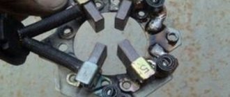
Checking the starter brushes
The fastest way to check brushes is with a 12-volt test light. One terminal of the lamp is connected to the brush holder, the other to the housing. If the light comes on, it's time to change the brushes.
You can also check the brushes with a tester - a multimeter. To do this, the starter needs to be disassembled. The main goal is to check for a short to ground. Normally, the brushes should not short-circuit.
Bendix starter diagnostics
Bendix in good condition only spins in one direction. Remove it and hold it in a vice, try turning it in both directions, if it turns in both directions, change the bendix.
Checking the starter armature
To do this, you will need to directly supply 12 volts from the battery to the starter. In other words, voltage is bypassed into the relay.
If the starter turns, then the armature is OK. If there is no rotation, then both the armature and the brushes may be problematic. In such a situation, the starter needs to be disassembled, then troubleshooted and checked with a multimeter, switching the device to ohmmeter mode to measure resistance.
Anchor repair
One of the most common problems in the operation of the armature of the starter assembly is a short circuit, in particular, we are talking about the windings located on the housing. In order to solve this problem, you will need to carry out a visual diagnosis of the outputs of the inka, as well as the wiring of the element. By doing this, you will be able to find the place where the breakdown occurred. After it is found, it is necessary to clean the contacts and diagnose the resistance; a multimeter is used for this. After this, you should insulate the broken area, for which you can use super glue with asbestos.
If a visual check does not allow you to find the location of the breakdown, you can use another method for diagnosis. It consists of connecting all the lamellas of the device together, but for this it is necessary to use a special stripped wire. When the lamellas are closed, voltage will need to be applied to the device (to the commutator and ground), and since it must be as high as possible, this may require a welding machine. Actually, this is precisely the complexity of the method. The place where there is a breakdown will burn out (video author - Konstantin Petrakov).
In the event that an interturn short circuit occurs in the operation of the unit, such a problem can be determined using a special device. That’s what it’s called - PPYA - a device for checking the anchor. As practice shows, short circuits are often caused by the use of bent or crumpled wires or the presence of conductive particles between them. If this is the case, then it is necessary to correct all the problems (align the wires and clean them of debris), and then apply a layer of varnish on top, this will protect the device. If this method does not help you find the problem, you can rewind the armature yourself.
As for a short circuit, it usually affects the functioning of the collector. Subsequently, this can lead to burnout of the plates, as a result of which this element can completely collapse. If you have to solder, remember that before soldering the working surfaces must be thoroughly cleaned; you can use a drill for this. Using this device, you can perform a good cleaning of contacts, as well as lead wires. When the wiring is installed back into the so-called cockerels, it will need to be checked using an armature diagnostic device.
If you will be soldering, we recommend purchasing inactive flux as a material, as well as tin. Before starting the process, the soldering iron should be warmed up as much as possible, this will allow you to achieve the desired result. It is also necessary to warm up the wires, since the solder must melt well so that it can get into the soldering area. When the soldering is completed, it will be necessary to treat this area with a solvent, and then again diagnose the armature using the device.
As practice shows, our compatriots often face the problem of wear of collector plates, and uneven wear. In addition, the commutator can even move relative to its axis - all these malfunctions are usually caused by wear of the brush assembly or the commutator as a whole. If we talk about plates, then this problem manifests itself as a result of a loose fit of the brush elements, which contributes to the formation of a so-called arc during operation, which wears out the plates. If this is the case, then grooving the manifold will solve the problem, but keep in mind that this will require a special lathe. When the grooving is completed, the device will need to be cleaned of chips and other dirt that could cause it to malfunction.
Starter performance monitoring sequence
If, when turning the ignition key to the “Start” position, the starter does not show any signs of life, you must perform the following sequence of actions:
1. Measure the voltage at the battery terminals with a multimeter. There must be at least 12 volts to start the engine. If less, you should charge the battery.
2. Next, you need to measure the quality of the vehicle's ground tire. You should check the contacts of the “minus battery” bus - the car body and the “minus battery” bus - the engine body, actually the starter. This is best done by turning on the ignition and measuring the voltage between the battery negative, the metal elements of the engine body and the stripped elements of the engine body. Voltages must be strictly 0.0 Volts. If more, the connection contacts may be broken.
3. Before carrying out further actions, it is better to perform computer diagnostics. In many cars, the engine may be blocked by the immobilizer, which may require key binding. A malfunction of the automatic gearbox components can also introduce a prohibition mode for starting the car.
4. For further diagnostics of the starter, an electrical diagram of the vehicle and a diagram of the location of relays and fuses are required. The car's starting system can be organized in one of two ways. In cars of earlier years of production, voltage was supplied to the starter solenoid relay directly from the ignition switch contact group. A malfunction of the contact group leads to a lack of voltage supplied to the solenoid relay. In this case, it is necessary to check the presence of contacts according to the ignition switch connection diagram. Modern vehicles control starter activation using a starter relay, usually located in the relay and fuse box under the hood. It is necessary to check the serviceability of the relay, the presence of +12 Volts at its input contact. You can force the starter to turn on by closing the relay contacts.
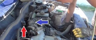
5. Next, proceed directly to work with the starter. It is usually located in the flywheel area. A more convenient location is between the engine and the radiator of the cooling system. In this case, access to it is simplified. It is worse if the starter is located behind the engine under the exhaust manifold. In any case, it is necessary to trace the path of the wires coming from the starter. Two conductors extend from it: one thick (cross-section of at least 25 sq.mm.) for starting the electric motor and a thin one for controlling the solenoid relay.
6. First of all, it is necessary to strip the thin conductor in a convenient place and connect a wire with a cross-section of at least 2 sq. mm to it. and insulate the connection point. Then move the gearbox to neutral. After this, connect the connected conductor to the positive terminal of the charged battery. If there is no action from the starter, the following options are possible:
- malfunction of the solenoid relay winding (break);
- wear of the starter motor brushes;
- failure of the collector lamellas;
- armature winding break;
- lack of contact on the connector of a thin wire (often occurs when a thin wire comes into the connector “under the chip”, sometimes it’s enough just to move it);
- lack of grounding on the car engine body (to be more sure, you can connect the engine body to the battery negative with a powerful wire).
7. If the solenoid relay works reliably, but the starter motor does not rotate, you should check the presence of + 12 Volts at the output of the thick conductor. It usually has a “nut” connection, sometimes the contacts burn and char. In this case, the contact areas should be removed and cleaned. You should also check the connection of the thick conductor in the area of the positive terminal of the battery.
8. Using a multimeter, you can check the resistance of the coil of the solenoid relay (between the connected conductor and the motor housing, it should be in the range from 3 to 20 Ohms for different types of starters).
9. If the previous actions did not lead to a positive result, it is necessary to begin diagnosing the malfunction on the starter removed from the vehicle.
Video - how to close the starter directly if it does not turn:
Video “Repairing the starter unit at home”
How to properly repair a device and what nuances need to be taken into account - learn from the video (author - AUTO RES channel).
Probably every car owner has encountered the problem of being unable to start the engine. As practice shows, often the cause of a malfunction is the starter device, which refuses to work. You can learn more about how starters are diagnosed and repaired in this material.
Checking an asynchronous electric motor
In addition to commutator motors, in everyday life you can also find asynchronous motors installed in some models of washing machines or in refrigerator compressors. Much more often they are used in compressors, pumps, various machines and other equipment. Despite their high reliability, these electric motors are also susceptible to breakdowns and malfunctions. In these designs, the role of the armature is played by the stator windings, so visual inspection should begin with them.
Often the windings stop working when they become damp or the turns break. Therefore, if the motor has not been used for a very long time, it is necessary to check the insulation resistance using a megger. In the absence of a mgohmmeter, for preventive purposes it is recommended to disassemble the unit and dry the stator windings for several days.
It is quite possible that the cause of the malfunction does not lie in the electric motor itself, but is associated with some other factors. Therefore, before you start repairing the unit itself, you should make sure that there is voltage, check the magnetic starters, connection cables, and thermal relay. If there is a capacitor in the circuit, it also needs to be checked. If all of the above elements are in good working order, you can begin disassembling the engine for initial inspection. The test must be carried out in a complete absence of power supply. It is necessary to prevent spontaneous or erroneous switching on of the unit.
During the inspection, in addition to other parts, the stator windings are especially carefully checked. They must be intact, without protruding or torn wires
Particular attention should be paid to black spots indicating possible burnt wires. In good condition, the conductors are dark red in color.
Blackening occurs when the electrical insulating varnish applied to their surface burns out. During inspection, complete or partial burnout of the winding and interturn short circuit may be detected. With partial burnout, the engine will run and heat up quickly. Therefore, the winding is completely rewound in any case.
If the external examination does not produce results, further diagnostics should be carried out using measuring instruments. Most often, a multimeter is used for these purposes to determine the integrity of the winding and the presence or absence of a breakdown in the housing.
In 220V engines, the starting and operating windings are connected. The starting resistance should be 1.5 higher than that of the working one. In 380V electric motors connected by star or delta, the circuit is disassembled, after which each winding is wired in turn. The resistance on each of them should be the same, with a deviation of no more than 5%. Also, all windings must be connected to each other and to the housing. If the resistance value is not infinite, this indicates the presence of a breakdown of the windings on the housing or between themselves. In this case, they require a complete rewind.
The insulation resistance of the motor windings is checked separately. In this case, a multimeter will not help; you will need a 1000V megohmmeter connected to a separate power source. When performing measurements, one wire of the device touches the motor body in an unpainted place, and the other wire is connected in turn to each terminal of the winding. If the insulation resistance is less than 0.5 megohm, then the motor requires drying
When taking measurements, be careful not to touch the test leads. The equipment being measured must be de-energized, the duration of measurements is at least 2-3 minutes
The greatest difficulty is the search for interturn closure. It cannot be detected by visual inspection. For three-phase motors, special inductance meters are used, which normally show the same value on all windings. If there is damage, the inductance of such a winding will be the lowest.
Basic faults
In fact, the main malfunctions of the starter can be “disguised” as failures of other machine components. So, before disassembling and reassembling your faulty unit, you must first verify that it is not working.
To determine the type of failure, below are the main symptoms of a starter malfunction:
- When you turn the key, a click is heard, but the armature of the mechanism does not rotate. If it really is a problem with the starter, then the battery will be charged.
- Repair of starters and generators can be carried out if the electric motor turns the crankshaft slowly, and the power unit itself cannot start. An accompanying symptom of the problem will be increased battery drain.
- It is necessary to sort through the disassembled unit if an attempt to start the engine is accompanied by extraneous sounds - grinding, creaking, etc. Of course, this may be due to the operation of other components, including the generator.
- The device is heating up. To understand whether the node is heating up or not, you need to gain access to it. The mechanism can get hot for various reasons, but its overheating always indicates a malfunction.
Connection diagram of the mechanism to the battery and ignition switch
To prevent failure of the unit, the starter must be periodically maintained. Starter blocking can occur for various reasons, so maintenance is an integral part of the process.
As for the breakdowns themselves, they can be as follows:
- the drive is stuck on the armature shaft;
- the traction relay is unstable;
- the contacts on this relay could be stuck;
- the return spring has failed - this could be either the freewheel or the ignition switch;
- the bearing elements of the mechanism have failed;
- the journals on the armature shaft are worn out;
- the device fixing screws have loosened, resulting in the unit operating under vibration;
- damage to the teeth of the structure occurred;
- inside the structure itself, the pole lock became loose, which led to the anchor starting to touch it.
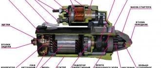
Why do you need a starter and its design features?
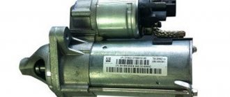
A starter (from the English word start - to begin) is a mandatory unit for starting the engine, which forcibly rotates the crankshaft flywheel to the speed necessary for independent operation.
It is a 4-pole DC electric motor that takes energy from a battery. The starter is necessary to start the engine of any vehicle and receives power from the battery when the key is turned in the ignition.
Dismantling the device
Before you remove the starter and how to repair it, you need to take into account that this task is quite labor-intensive. However, removing the starter and disassembling it is a prerequisite for troubleshooting.
How to remove the starter yourself:
- Before removing the starter, you need to disconnect the battery from the car's on-board power supply. Any repair work on the generator and other electrical devices is carried out with the on-board network disconnected.
- If you do not know how to remove the car starter, then after the on-board network is de-energized, you need to unscrew the nuts on the relay terminals of the unit, as well as on its body. If we take into account the different specifics of vehicle assembly, the starter can be mounted on different clamps. But usually a 13mm socket is required to dismantle the mechanism.
- After this, you need to disconnect the power wiring and move it away.
- If there is protection on the motor, it must be removed.
- After this, the nuts securing the device to the block are unscrewed. Having done this, the mechanism itself can be removed (the author of the video is Budni Autobusiness).
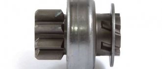
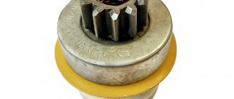
How to check bendix
The operation of the Bendix starter is also quite simple to check. You need to clamp the overrunning clutch housing in a vice (through a soft spacer so as not to damage it) and try to turn it back and forth, it should not rotate in both directions. It turns - the fault lies in the overrunning clutch, because when you try to turn it in the other direction, it must stop. Also, the bendix may not engage, and the starter will turn idle if it is simply stuck or the teeth are eaten away. Damage to the gear is determined by visual inspection, but the occurrence can only be determined by completely disassembling everything and cleaning the gearbox from dirt and dried lubricant inside the mechanism.
Indicator light for checking the starter winding
Assembly
Assembling the starter is the final stage of repair. Before assembling the starter, the shaft, gearbox, armature and bushings must be lubricated. How can you lubricate the starter before assembling it? For this, graphite lubricant, Litol, and motor fluid can be used. Assembling and installing the starter is carried out in the reverse order; after installation, it is necessary to check the functionality of the unit.
To make sure that the repair was carried out correctly, you need to apply a minus to the mechanism body, and a plus to the winding. If, after connecting, the bendix can move back and forth, while the relay contacts close normally, this indicates that the mechanism is fully working. After applying positive voltage to the electric motor, the motor should rotate evenly, and there should be no noise or sounds. If there are no sounds, then the mechanism is put in place.
If you made any mistakes in assembling the mechanism, it is not recommended to operate the vehicle. Otherwise, you may encounter a problem somewhere along the road, and the worst thing will be if it overtakes the driver while driving outside the city on the highway. Therefore, if you doubt that everything was done correctly or that mistakes were made during the work, it would be better to consult a specialist about this. Believe me, it’s better to pay a little once, but be sure that the machine will work normally, than to save money and face higher repair costs.
Sorry, there are no surveys available at this time.
Checking the starter with a multimeter
Having dealt with the methods described above, you can separately highlight how to check the starter with a multimeter. This method is optimal if there is no flaw detector or test lamp. The tester allows you to quickly test the brushes and starter windings for short circuits, as well as check the relay windings by measuring resistance.
- To quickly check the starter with a tester, just disassemble the device, then measure the resistance between the brushes and the plate, then between the winding and the housing. Next, measurements are taken between the commutator plates and the armature core, as well as the starter housing and the stator winding.
- At the same time, you need to obtain readings by taking measurements between the ignition switch contact and the permanent positive (we are talking about the shunt bolt for connecting the field windings of the starter electric motor).
This way you can check the condition of the relay coil. Normally, the indicator is from 1 to 1.5 ohms. We also recommend reading the article about why the starter continues to spin after starting the engine. From this article you will learn about the causes of this malfunction, as well as methods for diagnosing the repair of such a malfunction. - More measurements are taken between the ignition connection terminal and the traction relay housing. This allows you to check the holding coil of the solenoid relay. The norm is considered to be from 2 to 2.5 ohms.
Please note that there should be no conductivity between the housing and the winding, the rotor shaft and the commutator, the ignition contact and the positive contact of the relay, as well as between the two windings. Let us also add that the resistance of the armature windings is minimal; it cannot be measured with a simple multimeter.
The tester can only be used to ring the winding to ensure that there are no breaks. To do this, when checking, you need to make sure that each lamella of the collector is connected to the others. You can also check whether the voltage on adjacent lamellas drops after applying 1A DC current to them. Normally, the voltage is the same everywhere.
Basic faults
Let's consider the main malfunctions of the starter armature:
- Insulation breakdown to ground;
- Short circuit between turns;
- Wear of studs for bushings;
- Uneven wear of the collector;
- Wiring of collector terminals.
These malfunctions provoke failure of the car's starter, and, accordingly, the ignition system. As a rule, these breakdowns are not solved in an instant, but require some time and effort. Malfunctions can be solved with the help of specialists or on your own, but to carry out this work you need to stock up on the necessary tools and some equipment.
Malfunction of the starter retractor relay
This is precisely the reason for the malfunction of the starter retractor relay. The pull-in winding may be faulty. The relay clicks but the starter does not turn. Because the holding winding is triggered. But its current strength is not enough to compress the spring force and retract the relay armature and press the coin to the terminals.
Winding fault
This is a common malfunction. Because the main load falls on the pull-in winding. Because maximum effort is required to retract the anchor. This winding has a larger wire cross-section. Accordingly, a larger current is created in it than in the holding winding.
Carbon formation
Another malfunction of the solenoid relay is the formation of carbon deposits on the coin and terminals. As a result of exposure to a strong electric current, carbon deposits and burnout of the surface are formed on the coin and terminals as a result of their interaction. When connecting the nickel and the terminals, the carbon deposits do not make contact, and the electric current does not flow to the starter windings. On the solenoid relays where the cover with the terminals is removed. This problem can be easily solved. The nickel turns over to the other side. The terminals are cleaned.
Anchor repair
Short circuit of the windings on the armature body creates a huge problem. To deal with the breakdown and solve the problem, you need to carefully examine the outputs of the busbar and the wires coming out of the grooves and armatures.
This way you can determine the location of the breakdown. Having determined where the spark or arc appears, you need to thoroughly clean the contacts in this place and check the resistance with an ohmmeter.
Next you need to isolate the problem area. To do this, you can use a little asbestos and super glue. When reacting with asbestos, the glue hardens instantly.
If you cannot determine the location of the breakdown using the first option, you can use a more radical, but 100% option. To do this, you need to connect all the slats together using stripped copper wire or other material. After which you need to briefly apply voltage using a welding machine to the armature ground and the commutator. Thus, an arc will be observed at the point of the short circuit, and the place will burn out. In those rare cases when it is not possible to determine the location of the short circuit, the armature can be rewinded if you wish.
An interturn short circuit - this malfunction is determined using a special device called an “armature test device” (this is a kind of transformer).
Quite often, interturn closure occurs in visible areas. The cause of such a breakdown may be crumpled or bent wires on the winding, as well as conductive particles between them . In this case, it is necessary to remove all these interferences. After repair, it is advisable to apply a layer of varnish. This will create some protection. If this method doesn’t really help, you can also rewind the armature.
As a rule, a short circuit in the armature winding also negatively affects the commutator. As a result, its plates burn out and it is completely destroyed. The main rule when soldering is that if the surface is cleaned well, the soldering will be adequate.
Cleaning can be done perfectly well using a drill. You need to use it to clean the contacts of the cockerels, its surface and the wires leading to it. After the wires are installed back into the cockerels, the starter armature is checked using the PPY (armature test device). They check the possibility of an interturn short circuit or breakdown. If nothing is found, you can start soldering. As a material for soldering, it is better to use tin and inactive flux. Before soldering, you need to warm up the soldering iron well (it must also be massive at least one hundred W). The leads must be thoroughly heated to ensure excellent melting of the solder. It should completely penetrate into the soldering areas, this will create better contact. After the soldering is completed, the soldering area must be wiped with a solvent and the PCP must be checked again.
Very often there are cases that when disassembling the starter, one can observe uneven wear of the commutator plates, as well as its displacement relative to the axis. Each such malfunction causes wear of the brushes and complete wear of the commutator. So, wear of the plates occurs due to the fact that the brushes do not fit tightly to the commutator. As a result, during operation, a certain arc appears that wears out the plates. In this case, it is advisable to make a groove in the manifold using a lathe. Important: When installing an anchor on a lathe, great attention is paid to the centering of the tenon. Since the deviation from the norm should not exceed 0.05 millimeters. After the groove is completed, you need to clean the armature from chips and other foreign matter.
As a result of the above repair measures, we can assume that the starter armature has been repaired and is ready for use.
How we diagnose the starter.
In order to conduct a visual inspection of each starter part and diagnose it, we completely disassemble the unit.
Before disassembling, in rare cases we put it on a stand, and only the starter that we made before. The question is that there is a network power supply on the stand where the starting current is approximately 800 Amperes, and if the starter is shorted somewhere and this can be cured, then after such a start it will simply burn out.
Inspect the starter for mechanical damage.
Initially, the unit is inspected for various mechanical damages (chips, cracks in the housing, damage to the power bolts of the solenoid relay).
Next comes complete disassembly of the unit into its component parts for diagnostics.
Checking the starter armature.
The starter armature is inspected for mechanical or electrical damage. If there is a lot of wear on the starter bushings (starter bearings), the armature wanders and can cling to the stator winding. This results in scuffing and breakdown of the insulation of the stator windings.
Also, when the brushes wear out and the tight contact between the commutator and the brush disappears, an electric arc is formed and the armature commutator burns out and melts. Also, if the starter operates for a long time, or if the ignition switch is faulty, the armature spins and gets very hot, as a result of which the insulating varnish leaks out. Visually everything is fine, but in fact there is an interturn short circuit or an insulation breakdown.
Next, if visually the condition of the armature does not raise any doubts about its serviceability, a megohmmeter is checked for the insulation resistance of the winding.
Finally, the armature is checked for interturn short circuit of the windings.
Checking the starter brush assembly.
The brush assembly is inspected for mechanical or electrical damage. When the armature commutator falls apart, the assembly can simply be broken, twisted without any obvious influence of current, or there may be an option when the driver twists to the limit, while the commutator, assembly and brushes become very hot and begin to collapse, forming carbon deposits, burnouts, and splitting of the graphite of the brushes into layers .
Next, if the node is visually normal, it is checked with a megohmmeter for insulation resistance.
Next, you need to determine the degree of wear of the brushes by visual inspection.
Checking the starter stator.
If the stator is based on permanent magnets, then it is inspected for cracks, chips, unstuck magnets, and the presence of any metal parts of the starter in the form of magnetized particles.
If the stator is based on a classic winding, then it is inspected for mechanical damage, melting, burnouts, rust, and desoldering. Next, it is checked with a megohmmeter for the insulation resistance of the windings.
In powerful, large stators, usually from trucks, part of the insulating coating must be opened to inspect and check the interturn insulation. When they use “launchers” or “tarzans”, the strength of the starting current is such that on the outside the winding looks great and doesn’t even penetrate the housing, but inside it’s just a mess, the wire simply melts.
Checking the starter solenoid relay.
Visual inspection for mechanical damage to the housing, damage to the power bolts, inspection of the starting terminal for breakage and souring.
Inspect the integrity of the rear insulating cover.
If all is well, the relay is started by applying operating voltage, the operation of the pull-in winding and the holding windings is checked, and the voltage loss across the contacts is measured.
In relays where it is possible to remove the insulating cover, it is removed and the contacts are inspected for carbon deposits and wear.
Checking the starter gearbox.
Inspection for mechanical damage (the Bendix guide splines break off, the gearbox shaft bursts. The planetary gears and gearbox sprockets fall apart).
Bendix check.
Inspect the gears and guide splines for chips and licking.
Checking the Bendix for failure. This operation is done when the starter is already fully assembled. The unit is placed on a stand and screwed very tightly. A special device is brought to the Bendix, which holds the gear dead and the launch is carried out. The stand measures the force of the moment with which the bendix presses, and if the bendix is weak, it simply breaks it off.
Checking the front and rear starter covers.
The bushings or bearings are checked for wear and play. Look at the seat for the bushing or bearing on the head (aka dome or front cover) of the starter.
The seats for the bushing or bearing of the starter rear cover are checked.
The mounting holes are inspected, since they are also broken due to vibration or insufficient tightening of the bolts.
How to determine the location of the short circuit
If the armature windings are shortened, this can lead to big problems. To be able to deal with the breakdown and fix it, you will need to carefully inspect the exits.
A visual inspection can provide definitive answers. Almost every experienced motorist, and what’s more, a specialist, should be able to make an assessment already at the visual inspection stage. Just as there is no smoke without fire, there is no short circuit without traces of burning.
After determining the location of the short circuit, you should clean the contacts and then check the resistance with a measuring device set to Ohms (a multimeter, for example).
Isolating the problem area is the next stage of work. A mixture of asbestos with super glue will help, which will give the composition the property of instantly hardening.
If the location of the breakdown still cannot be determined, you still need to use a simple method. Take stripped copper wire, which needs to be used to tie all the lamellas so that they connect and influence each other. Then a pulse is applied for a short time in order to determine the weak point. Current can be successfully applied using a welding machine, acting on the ground and commutator. Where the welding arc will pierce is where the short circuit will occur.
As a last resort, if again it was not possible to identify the location of the short circuit, the armature winding can be rewinded entirely.
Interturn short circuit or IFZ is the number one fault of the armature. It is determined using a special apparatus that is designed specifically for these purposes. It's called PYA. It is a transformer that effectively detects faults.
MFZ accounts for almost half of all malfunctions associated with electric motors (which, in fact, is the starter). The reasons for the occurrence of MZHZ should be sought in overloading of the device, erroneous operation and initial standard defects.
It is noteworthy that improper operation of the starting device threatens the penetration of water into the windings.
How to find MZHZ? Determining it is not so difficult if you use available tools and the apparatus described above.
Here are several other ways to determine the MFZ of an anchor:
- When the starter is operating, the device heats up unevenly; some part, if you touch it, is very hot;
- Measuring the load on each phase with current clamps (obviously, if there is more current in one of the phases than in the others, this is a problem);
- Ringing the windings with a tester, which implies that a separate ringing is required (each winding separately, which makes it possible to verify the obtained resistance values);
- Check with a megger, which will allow you to determine a short to the housing (one terminal of the device is applied to the starter housing, the other to the output of the windings).
The best and most accurate test of the anchor on the MZHZ is the use of the Grover Tester (American name) or, in our opinion, the PPY. True, the anchor must already be removed and the starter disassembled.
A PYA is a transformer that has only a primary winding, and a gap is cut out in the core where the armature is placed.
The check is carried out like this:
- The anchor is placed in this gap;
- The PPP is connected to the 220V network;
- Any piece of metal strip is anchored;
- If a piece of metal begins to vibrate or become magnetized, it means that there is an MFZ in the armature.
Don't forget to rotate the armature around the entire circle, since the MFZ may not be in one plane, but present in another.
Checking the armature for interturn short circuit
Electrical machines consist of a rotor and a stator.
The stator consists of stationary windings placed in a housing. The anchor is a moving part, so as a rule, particles of dirt and grease get on it and, under the influence of temperature, an oxidized coating is formed. It can cause malfunction or failure of the rotor of an electrical machine. It is detected by visual inspection. Carbon deposits can cause interturn short circuits in the armature. As such, the motor rotor does not wear out under normal operating conditions. Over time, only current-collecting brushes must be replaced if their length no longer corresponds to the permissible size. However, prolonged loads cause heating of the stator windings, which ultimately contributes to the formation of carbon deposits. Interturn closure of the armature can occur due to mechanical damage. The presence of chips, dents, scratches and cracks on rubbing surfaces is unacceptable. A short circuit between the turns of the armature windings occurs in the event of failure of the bearing units. Then the anchor warps, which leads to damage to the lamellas. Another cause of short circuiting is exposure to moisture. When water drops hit metal surfaces, the corrosion process begins. Rust makes it difficult for the armature to rotate, current loads increase, heating occurs, as a result of which the solder can peel off, which in turn, during long-term operation, can lead to an interturn short circuit. It is possible to diagnose this malfunction at home. This procedure is carried out using an inductor called a choke.
Using this device, you will be able to find out the direction of the reset, as well as the order in which the winding coils are connected to the commutator lamellas.
Thus, the armature is checked for interturn short circuit.
Making such a device with your own hands is not at all difficult; just read the contents of our step-by-step instructions.
To assemble the device, you will need U-shaped transformer iron. It can be removed from the Baby type vibration pump.
We disassemble the structure and take out the U-shaped transformer iron. To do this, it is first necessary to heat the lower part of the pump so that the polymer with which the coils are filled melts.
Next, using a handy tool, we cut off the edges on the transformer iron, as shown in the photo. When processing, remember that iron is laminated, so all operations must be performed carefully to avoid scoring. Then use an emery machine to remove all sharp edges on the product. This is necessary to maintain the integrity of the enamel wire.
It is not necessary to observe strict dimensions of the corners, the main thing is that anchors of different sizes can be easily located in the prepared place.
The next step is to make the coils. To gain in the size of the device and the choke not to be too bulky, we will make not one, but two coils, which we will place on both sides of the U-shaped iron. To do this you will need:
- cardboard;
- measuring instrument;
- pencil;
- sharp knife;
- scissors.
We measure all dimensions of U-shaped transformer iron according to their maximum values. Next, we transfer them to cardboard and draw out the outline of the body of the future coil. In this case, it is necessary to take into account the size of the core groove. Next, use the blunt end of the scissors to follow all the fold lines. This will help you bend the cardboard without any problems. Cut out the development. In the same way we make a pattern for the other side. Now we need to prepare the covers for the coils. You will need 8 of them. We mark the blanks for the lids on the cardboard. We cut out the outer contour with scissors, the inner contour with a sharp knife.
Next, we glue the covers with the prepared developments and get two skeletons of future coils.
Now you need to wind the wire onto the coils. To do this, we will use the calculation of the transformer. First, we determine the cross-sectional area of the core by multiplying its length and width. In our case, the area was 3.7 cm x 2.2 cm = 8.14 cm 2. Next we divide 13200/8.14=1621 turns. We round this amount to 1700 turns and distribute it equally between the two coils, resulting in 850 turns each. This amount can be wound manually without any problems. In this case, an error of 20-40 turns will not affect the result. But it’s still better to err on the side of increasing. Before you start winding, you need to make holes into which the ends of the wire will go. A heat-shrinkable tube is placed on the free end of the wire. The end of the wire is inserted into the hole and then the winding process begins. Upon completion, solder the wiring with a cambric to the other end and insert it into another hole. We wind the second coil in the same way.
After both coils are ready, we put them on the U-shaped core, while the wire leads should be located at the bottom on one side. It is important that the coils are wound identically, the turns are directed in the same way, and their ends point in the same direction. Next comes the connection of the beginnings of the induction coils and the supply of mains voltage (220V) to their ends.
To test a homemade throttle, we will use a factory-made device. First, let's check the armature for interturn short circuit with an industrial device and mark the places where the plate sticks with chalk. When checking the rotor with our choke, the plate will be magnetized in the same places. To summarize, the device was made correctly, the results are identical.
We remove the coils from the core and insulate them with electrical tape. We put them back and solder the power. The choke is ready for operation, you can start checking for the presence of an interturn short circuit in the armature.
To do this, you need to turn on the device we made, place the anchor in its cutout and slowly turn it.
Checking turn-to-turn short circuit using an analog tester
However, you can check the armature for an interturn short circuit using a multimeter. In this case, you will only be able to find out whether there is a break in the armature windings or not. A more accurate device would be an analog tester. With its help, we measure the resistance between each two lamellas. It must be identical. After that, we set the device to 200 kOhm. We connect one probe to ground, and apply the other to each lamella. If the armature does not ring to ground, then it is most likely serviceable or needs to be checked using a throttle.
Indicator for detecting armature interturn short circuit
To detect an interturn armature short circuit, you can use a simple indicator that can be assembled according to the diagram below.
In order to solder such a basic indicator you will need some money, free time and your hands.
We purchase 5 transistors, 8 resistors, 4 capacitors, 2 LEDs and a battery. In addition, we wind two coils ourselves.
We prepare the printed circuit board and assemble the device. It is very convenient to check inter-turn short circuits using such an indicator. A strong argument in favor of the device is that it can easily find turn-to-turn short circuits on stators as shown in the video below.
If an interturn short circuit is detected on the armature, what should I do?
You need to check everything; if the metal ruler is attracted in a certain groove, this means that there is an interturn short circuit in its coils.
Also, take a close look at the manifold.
If a short circuit occurs between its lamellas, this also indicates the presence of an interturn short circuit.
Most often in such situations it is necessary to completely rewind the armature, since even one winding without causing damage to the others seems to be very problematic.
In addition, you can find out about the presence of an interturn short circuit by simply carefully inspecting the wire and armature bars.
For example, it may be discovered that the turns are dented or bent, and that various kinds of particles that conduct current are visible between them, for example, solder that has leaked after soldering.
In this case, the breakdown can be eliminated by removing foreign bodies or correcting bruises on the tire.
Therefore, it is much easier to repair interturn armatures than it seems.
In addition, it is recommended to varnish the parts after repairing the short circuit.
Among other things, another sign of the presence of an interturn short circuit is sparking of the brushes.