There are several different types of engines, and in wheeled, tracked, water and sometimes even air transport (trucks and cars, special equipment, motor boats, airplanes, etc.), you can often find an internal combustion engine (ICE).
Internal combustion engines are gasoline and diesel, and can also successfully run on gas and even hydrogen (hydrogen internal combustion engine). Motors also differ in design and layout; they are two-stroke and four-stroke.
One way or another, a power unit of this type has become widespread due to its autonomy, versatility, as well as a number of other advantages. At the same time, the units have many different parameters and characteristics, among which it is worth highlighting the operating cycle. Next, we'll talk about what the duty cycle of an automobile internal combustion engine means.
The first stroke is intake.
The structure of a modern engine
|
The piston moves from TDC to BDC, and purified air enters the cylinder through the open intake valve (due to the vacuum created by the piston). The air is mixed with a small amount of exhaust gases remaining from the previous cycle, the temperature rises and at the end of the intake stroke reaches 300-320 K, and the pressure 0.08-0.09 MPa. The cylinder filling coefficient is 0.9 or higher, i.e. more than that of a carburetor engine.
What are the main differences?
Features of operation require consideration first in order for the comparison to be correct:
- In diesel engines, the air-fuel mixture is formed much faster when compared to a unit running on gasoline. In the cylinders of such engines, only air is compressed, the temperature of which corresponds to approximately 900 degrees. Gasoline is supplied separately to the compartment for subsequent combustion. Small fragments of diesel fuel evaporate at an accelerated rate and combine with the air mass. Due to the sufficiently high temperature effect, the resulting mixture is easily ignited without the need for ignition with a spark. Such engines consume significantly less oil.
- Air and fuel in gasoline engines are combined in a specially designed exhaust manifold, after which the fuel enters the compartment for further combustion. When the compression stroke is completed, the final stage of formation of the fuel-air composition is completed and its subsequent distribution throughout all compartments of the cylinder. After squeezing, the resulting mixture reaches a temperature of approximately 500 degrees, and then the procedure of igniting it using a candle is performed.
The third stroke is the working stroke.
At the end of the compression stroke (20-30 degrees of rotation angle of the crankshaft before the piston reaches TDC), a portion of fuel is injected in a finely atomized form through a nozzle into the cylinder under high pressure (15-20 MPa) using a pump. Fuel evaporates when it comes into contact with heated air, its vapors mix with the heated air and ignite. When fuel burns, due to the supply of a large amount of heat, the depletion and temperature of the resulting gases sharply increase. At the beginning of the expansion stroke, the gas pressure is 7-8 MPa. and the temperature is 2100-2300 K. Under the influence of pressure, the piston moves from TDC to BDC, performing useful work. The volume of the cylinder increases, the pressure and temperature of the gases decrease and when the piston approaches BDC they are 0.2-0.4 MPa.
Rocket engine
The rocket engine is the simplest of its family, so let's start with that.
In order to function in outer space, rocket engines require a supply of oxygen, as well as fuel, for their operation. The oxygen-fuel mixture is injected into the combustion chamber where it burns continuously. Gas under high pressure exits through the nozzles, causing thrust in the opposite direction.
To try this principle yourself, blow up a toy balloon and release it from your hands - a rocket engine works much the same way 
The fourth measure is release.
The piston moves from BDC to TDC. Through the open exhaust valve, the exhaust gases are pushed out through the exhaust pipe into the environment. At the end of the exhaust stroke, the gas pressure is 0.11 -0.12 MPa, the temperature is 850-1200. After this, the diesel operating cycle is repeated. In two-stroke engines, the time allotted for the working cycle is used more fully, since the exhaust and intake processes are combined in time with the compression and power stroke processes. The operating cycle occurs over 360 degrees (one revolution of the crankshaft).
When the piston moves from TDC to BDC, expansion and exhaust processes occur simultaneously with purging of the cylinder, and when the piston moves back from BDC to BDC, intake and compression occur. Changes in cycle parameters (pressure and temperature) correspond to changes in four-stroke engine parameters. A comparison of the operating cycles of four- and two-stroke engines shows that with the same cylinder dimensions and crankshaft rotation speed, the power of two-stroke engines is 1.5–1.7 times higher. It is simpler in design and more compact. The disadvantages of a two-stroke engine include the limited gas exchange time, which impairs the cleaning of the cylinder from exhaust gases, increases the loss of part of the fresh charge, and reduces efficiency.
Diesel engine operation, more details
Turbofan engine
A turbofan engine is something of a compromise between a turbojet and a turboprop. It works like a turbojet, but there is one peculiarity: the turbine shaft rotates an external fan, which has more blades and spins faster than the propeller. This helps this engine remain efficient at high altitudes where the air is thin.
Sources: www.animatedengines.com
- Ultimate Visual Dictionary, DK Publishing Inc., 1999
- Building the Atkinson Cycle Engine, Vincent Gingery, David J Gingery Publishing, 1996
- The Stirling Engine Manual, James G. Rizzo, Camden Miniature Steam Services, 1995
- Modern Locomotive Construction, J. G. A. Meyer, 1892, reprinted by Lindsay Publications Inc., 1994
- Five Hundred and Seven Mechanical Movements, Henry T. Brown, 1896, reprinted by The Astragal Press, 1995
- Model Machines/Replica Steam Models, Marlyn Hadley, Model Machine Co., 1999
- Air Board Technical Notes, RAF Air Board, 1917, reprinted by Camden Miniature Steam Services, 1997
- Internal Fire, Lyle Cummins, Carnot Press, 1976
- Toyota Web site Prius specifications
- Steam and Stirling Engines you can build, book 2, various authors, Village Press, 1994
- Knight's New American Mechanical Dictionary, Supplement Edward H. Knight, A.M., LL. D., Houghton, Mifflin and Company, 1884
- Thomas Newcomen, The Prehistory of the Steam Engine LTC Rolt, David and Charles Limited, 1963
- An Introduction to Low Temperature Differential Stirling Engines James R. Senft, Moriya Press, 1996
- An Introduction to Stirling Engines James R. Senft, Moriya Press, 1993
UPD:
I added Wankel and CO2 engines, they seemed to me the most interesting and practically useful.
UPD2:
Added a description of a whole family of jet engines: rocket, turbojet, turboprop, turbofan.
How does a gasoline internal combustion engine work?
I take all photos and gifs from the Internet!
So, the engine is one of the most important parts of the car. We simply won’t drive without it, so it makes more sense to start studying the car with it. Well, let's get started.
Let's start with the most basic part of the engine - the crankshaft. This is what he looks like.
Believe it or not, it is he who makes your car go. Naturally, not by himself, but with assistants. The crankshaft with all its assistants is called the crank mechanism.
And the assistants and main driving force of the crankshaft are connecting rods and pistons, which are located on these connecting rods. All this equipment is successfully located in the main part of the engine - the cylinder block . And below we present you a small gif of how it all moves.
The pistons move up and down, causing the crankshaft to spin. It is thanks to the rotation of the crankshaft that the car moves. We will look at how this rotation goes to the wheels later, but for now let’s take a closer look at the cylinder block.
This is what the cylinder block looks like, inside which the crankshaft and pistons are located. It is the heaviest part of the engine, so never attempt to lift it alone. Although it is possible, it is not worth it. You'll hurt your back.
Gas distribution mechanism
Why can't we see the pistons? Yes, because the cylinder head is located on top of the cylinder . We will call it the cylinder head. Between the block and the head there is a cylinder head gasket - also an important component, which we will talk about later.
It is into the head that we screw the spark plugs when we change them. But it contains a more complex and no less important mechanism - the gas distribution mechanism. On the head there is a shaft that somewhat resembles a crankshaft, but not quite. He looks like this
This shaft is called a camshaft and it did not get this shape by chance. After all, underneath there are special valves that must open at the right intervals. These valves allow gasoline into the cylinders and exhaust gases out. That's why they are called inlet and outlet. We will consider an 8-valve engine, which has 1 intake and 1 exhaust valve for each cylinder. It is not difficult to guess that the engine is a 4-cylinder. It has 4 pistons.
This is what the process of opening and closing valves looks like when the camshaft operates.
As you may have guessed, the camshaft rotates thanks to a belt that transmits rotation from the crankshaft. The operation of these shafts is clearly synchronized and forms engine cycles for each cylinder. This belt is called a timing belt .
Engine strokes
So, we have already studied the two main components of the motor, and now let’s talk a little about the processes that occur during engine operation. All these processes are called strokes of a four-stroke engine. What are these four measures?
Answer
Carburetor engines are engines running on liquid fuel (gasoline) with forced ignition. Before being supplied to the engine cylinders, fuel is mixed with air in a certain proportion using a carburetor.
Diesel engines are engines that run on liquid fuel (diesel fuel) with compression ignition. Fuel is supplied by a nozzle, and mixed with air occurs inside the cylinder.
When operating an internal combustion engine, out of every ten liters of fuel used, unfortunately, only about two go to useful work, and the rest go to “warming” the environment. The efficiency of currently produced engines is only about 20%. But the world has not yet come up with a more advanced device that could operate for a long time and reliably at a higher efficiency.
Operation - Duty Cycle
| Diagram of the filtration plant at the Kalmius Central Processing Plant.| Filter installation. |
The work cycle operations are regulated automatically using a time relay, without the use of manual labor.
Each operation of the work cycle is specified by one command.
The four operations of the working cycle are automatically controlled by a time relay. Typically, calculating a material balance requires about 30 cycles, during which time it is possible to collect cracking products in quantities sufficient to determine all components. The temperature is regulated by automatic point devices (regular pockets are used to insert thermocouples) and is automatically recorded. Each reactor has two thermocouples installed in the lower and upper zones of the catalyst bed. Temperature measurements at these two locations indicate whether the catalyst bed is sufficiently mixed.
Of all the operations in the centrifuge operating cycle, the most power consumed is Unloading. In this case, the power is spent on overcoming the forces of inertia and adhesion of particles of the rotating layer of sediment, directed by the cutting mechanism for unloading. The lowest load is observed during the Drying operation, when power is spent mainly on ventilation losses and to a small extent on friction in the bearings.
| Hydraulic and kinematic diagrams of the moving and turning mechanisms of excavators. |
Thanks to this, all operations of the working cycle are controlled using two handles located on both sides of the steering wheel in the range of the driver’s hands. The design of the handles allows you to move them not only back and forth and left and right, but also in any other direction. When the lever moves diagonally, two hydraulic valve spools are simultaneously activated and the two working movements in the cycle are combined in time.
| Block diagram of indexing of single-bucket universal excavators. |
The working process of an excavator includes the operations of the work cycle and the operation of moving the machine, which is carried out after it becomes impossible or inconvenient to excavate the soil from the parking lot.
Depending on the sequence of operations of the working cycle, the loading process of the engine of a single-bucket excavator is formed. The methods outlined in the specialized literature make it possible to determine the average power removed from the engine crankshaft during each operation of the operating cycle.
It has a number of devices that allow you to automate most of the operations of the working cycle, in particular the supply of pipes to the inspection area, its rotation during the inspection process and the removal of the pipe after the end of the inspection to the rack.
Machines of this type are characterized by continuous rotation, frequency of work cycle operations and automation of these operations. Loading the centrifuge, the jointing process itself, washing, removing and unloading the sediment are carried out strictly periodically, at certain intervals; they also continue for a certain time and are controlled by a special automation system that manages and controls all operations. The worker's functions are reduced solely to starting the machine, which can then work without stopping for an indefinitely long time.
Advanced crane operators widely combine crane operating cycle operations when loading and unloading containers. Simultaneously with the movement of the container in the transverse or longitudinal direction, the container is raised or lowered to a height that ensures the safety of further movement. When operating gantry and overhead cranes, just like when operating jib cranes, a combined loading and unloading method is used. To combine individual operations in the work cycle, it is advisable to use the method of parallel processing of platforms and vehicles. To do this, cars approach certain areas, and the crane, moving along the front, simultaneously processes the platforms and cars. The downtime of individual vehicles is increasing slightly, but the average downtime of vehicles at the container site is decreasing.
Branch broaching can be done with one or three cores. All operations of the working cycle - loading, supply of blank pipes, removal of bends from the core - are carried out mechanized.
By introducing the method of Stalin Prize laureate F.L. Kovalev into excavation work, one can achieve great success in increasing the productivity of the machine. Different Stakhanovites perform the operations of the excavator working cycle using different techniques, so the duration and effectiveness of these operations are not the same for different excavator operators. Kovalev allows you to select, study and implement only the best techniques of the Stakhanovites and thereby achieve the greatest productivity.
Marine internal combustion engines (SICE)
Diesel engine is a piston internal combustion engine operating on the principle of self-ignition of atomized fuel
IA Neftegaz.RU.
The first marine internal combustion engines (ICEs) appeared at the beginning of the 20th century. The Danish ship Zealand, built in 1912, had a diesel installation with 2 diesel engines with a power of 147.2 kW each.
Currently, the bulk of the main power plants installed on ships are internal combustion engines.
Only ships with engine power from 14,700 to 22,100 kW have steam turbine installations.
A diesel power plant consists of one or more main engines, as well as the mechanisms that serve them.
Depending on the method of implementing the working cycle, internal combustion engines are divided into 4-stroke and 2-stroke.
An additional increase in power is achieved through supercharging.
According to the rotation speed, internal combustion engines are divided into: low-speed diesel engines with a rotation speed of 100-150 rpm, which directly drive the ship propulsion system; medium speed - 300-600 rpm, which drive the ship's propulsor through a gearbox.
Until the end of the 60s, reversible main engines were installed on ships, allowing the ship to reverse. Only at low power, special devices (reversing gearboxes) were used to reverse the internal combustion engine, allowing maneuvering.
In the 60s, simultaneously with the advent of adjustable pitch propellers, non-reversible internal combustion engines began to be used as the main engine, first on small ships, trawlers and tugs, and then on large merchant ships. Due to this, the design of the engines has been simplified.
Torque and horsepower
Car enthusiasts often debate with each other about whose engine is more powerful. But sometimes they have no idea what this parameter consists of. The generally accepted term "horsepower" was coined by inventor James Watt in the 18th century. He came up with it while watching a horse that was harnessed to a mechanism that lifted coal from a mine. He calculated that one horse could lift 150 kg of coal to a height of 30 meters in a minute. One horsepower is equivalent to 735.5 watts, or 1 kW is equal to 1.36 hp.
First of all, the power of any engine is assessed in horsepower, and only then do they remember the torque. But this traction characteristic also gives an idea of the specific traction and dynamic capabilities of the car. Torque is an indicator of the operation of the power unit, and power is the main parameter for performing this work. These indicators are closely related to each other. The more horsepower an engine produces, the greater the torque potential. This potential is realized in real conditions through the transmission and axle shafts of the machine. Connecting these elements together determines exactly how power can be converted into torque.
The simplest example is comparing a tractor with a racing car. A racing car has a lot of horsepower, but torque is required to increase speed through the gearbox. To make such a car move forward, very little work is needed, because the bulk of the power is used to develop speed.
As for the tractor, it may have an engine with the same displacement that produces the same horsepower. But in this case the power is used not to develop speed, but to generate traction (See traction class). To do this, it is passed through a multi-stage transmission. Therefore, the tractor does not develop high speeds, but it can tow large loads, plow and cultivate the land, etc.
In internal combustion engines, force is transmitted from the gases of the burning fuel to the piston, from the piston it is transmitted to the crank mechanism, and then to the crankshaft. And the crankshaft, through the transmission and drives, spins the wheels.
Naturally, engine torque is not constant. It is stronger when a greater force acts on the shoulder, and weaker when the force weakens or ceases to act. That is, when the driver presses on the gas pedal, the force acting on the shoulder increases, and, accordingly, the engine torque increases.
Power ensures overcoming all kinds of forces that prevent the car from moving. This is the friction force in the engine, transmission and drives of the car, aerodynamic forces, wheel rolling forces, etc. The more power, the greater the resistance of forces the machine will be able to overcome and develop greater speed. However, power is not a constant force, but depends on engine speed. At idle the power is the same, but at maximum speed it is completely different. Many car manufacturers indicate at what speed the maximum possible power of the car is achieved.
It must be taken into account that maximum power does not develop immediately. The car starts from a standstill at almost minimum speed (slightly above idle), and it takes time to mobilize full power. This is where engine torque comes into play. It will depend on it how long it will take for the car to reach its maximum power - that is, the dynamics of its acceleration.
Often the driver is faced with situations where it is necessary to give the car significant acceleration in order to perform the required maneuver. Pressing the accelerator pedal to the floor, he feels that the car is accelerating weakly. Fast acceleration requires powerful torque. It is this that characterizes the car’s throttle response.
The main force in an internal combustion engine is generated by the combustion chamber, in which the fuel-air mixture is ignited. It drives the crank mechanism, and through it the crankshaft. The lever is the length of the crank, that is, if the length is longer, then the torque will also increase.
However, it is impossible to increase the crank arm indefinitely. After all, then you will have to increase the stroke of the piston, and with it the size of the engine. At the same time, the engine speed will decrease. Engines with a large lever crank mechanism can only be used in large-sized boats. But in passenger cars with small crankshaft sizes you cannot experiment.
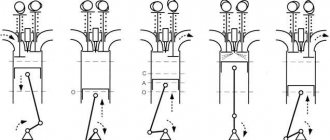
In a carburetor four-stroke single-cylinder engine (Fig. 1.3), the working cycle occurs as follows.
Rice. 1. Duty cycle of a four-stroke single-cylinder carburetor engine
Intake stroke. The piston is at i.m.t. and as the crankshaft rotates (in one half-turn) it moves from T.M.T. to n.m.t. In this case, the inlet valve is open and the outlet valve is closed. When the piston moves downward, the volume above it increases, so a vacuum equal to 0.07-0.095 MPa is created in the cylinder, as a result of which a fresh charge of the combustible mixture, consisting of gasoline vapor and air, is sucked through the intake manifold into the cylinder.
Due to the contact of a fresh charge with heated parts at the end of the intake stroke, it has a temperature of 75-125 ° C.
The degree of filling the cylinder with fresh charge is characterized by the filling coefficient, which for high-speed carburetor engines is in the range of 0.65-0.75. The higher the filling factor, the more power the engine develops.
Compression stroke. After filling the cylinder with a combustible mixture, with further rotation of the crankshaft, the piston moves from ground level. to e.m.t. The inlet valve 4 closes and the outlet 6 is closed. As the combustible mixture is compressed, its temperature and pressure increase. Depending on the degree of compression, the pressure at the end of the compression stroke can be 0.8–1.5 MPa, and the gas temperature 300–450 °C.
Expansion stroke, or power stroke. At the end of the compression stroke, the combustible mixture is ignited by an electric spark that occurs between the electrodes of the spark plug and quickly burns, as a result of which the temperature and pressure of the resulting gases increase sharply, while the piston moves from the top. to n.m.t. The maximum gas pressure on the piston during combustion for carburetor engines is in the range of 3.5–5 MPa, and the gas temperature is 2100–2400 °C.
During the expansion stroke, the connecting rod, pivotally connected to the piston, makes a complex movement and transmits rotation to the crankshaft through the crank. When expanding, gases perform useful work, therefore the stroke of the piston during this stroke of the crankshaft is called the power stroke. At the end of the piston's working stroke, the pressure in the cylinder drops to 0.3–0.75 MPa, and the temperature drops to 900–1200 °C.
Release stroke. The crankshaft moves the piston from ground level through the connecting rod. to e.m.t. In this case, the exhaust valve is open and combustion products are pushed out of the cylinder into the atmosphere through the exhaust pipe. At the beginning of the process of releasing combustion products, the pressure in the cylinder is significantly higher than atmospheric pressure, but by the end of the stroke it drops to 0.105-0.120 MPa, and the temperature of the gases at the beginning of the exhaust stroke is 750-900 °C, decreasing to 500-600 °C towards the end. It is almost impossible to completely clean the engine cylinders from combustion products (too little time), therefore, with the subsequent intake of a fresh combustible mixture, it is mixed with residual exhaust gases and is called the working mixture.
The residual gas coefficient characterizes the degree of contamination of the fresh charge with exhaust gases and is the ratio of the mass of combustion products remaining in the cylinder to the mass of the fresh combustible mixture. For modern carburetor engines, the residual gas coefficient is in the range of 0.06–0.12.
In relation to the power stroke, the intake, compression and exhaust strokes are auxiliary.
The operating cycles of a four-stroke diesel engine and a carburetor engine differ significantly in the method of mixture formation and ignition of the working mixture. The main difference is that during the intake stroke, not a combustible mixture enters the diesel cylinder, but air, which, due to the high degree of compression, is heated to a high temperature, and then finely atomized fuel is injected into it, which spontaneously ignites under the influence of high air temperature.
In a four-stroke diesel engine, working processes occur as follows.
Intake stroke. When the piston moves from T.M.T. to n.m.t. Due to the resulting vacuum, atmospheric air enters the cylinder cavity through the open inlet valve 5 from the air cleaner. The air pressure in the cylinder is 0.08–0.95 MPa, and the temperature is 40–60 °C.
Compression stroke. The piston moves from ground level. to e.m.t. The inlet 5 and outlet 6 valves are closed, as a result of which the upward moving piston compresses the air present in the cylinder. For fuel to ignite, the temperature of the compressed air must be higher than the auto-ignition temperature of the fuel. Due to the high degree of compression, the air temperature reaches 550–700 °C with an air pressure inside the cylinder of 4.0–5.0 MPa.
Expansion stroke, or power stroke. When the piston approaches T.M.T. Diesel fuel supplied by the fuel pump is injected into the cylinder through the nozzle. The injected fuel, mixing with heated air, self-ignites and the combustion process begins, characterized by a rapid increase in temperature and pressure. In this case, the maximum gas pressure reaches 6-9 MPa, and the temperature is 1800-2000 ° C. Under the influence of gas pressure, the piston moves from the top. to n.m.t. A working process is taking place. About b.m.t. the pressure drops to 0.3–0.5 MPa, and the temperature to 700–900 °C.
Release stroke. The piston moves from ground level. to v.m.t. and through the open exhaust valve 6, the exhaust gases are pushed out of the cylinder. The gas pressure decreases to 0.11-0.12 MPa, and the temperature - to 500-700 °C. After the end of the exhaust stroke, with further rotation of the crankshaft, the working cycle is repeated in the same sequence.
Engine performance indicators. The work done by the gases per unit time inside the engine cylinder is called indicated power.
Rice. 2. Operating cycle of a four-stroke diesel engine
The power received at the engine crankshaft is called effective power. It is less than the indicator for the value of power expended on pumping losses and on friction in the crank and gas distribution mechanisms of the engine, as well as on driving the fan, liquid pump and other auxiliary devices.
Thus, the effective power is less than the indicated power due to the mechanical losses consumed in the engine mechanisms and systems. Based on this, the mechanical efficiency (efficiency) of an engine is the ratio of effective power to indicated power.
Mechanical efficiency for carburetor engines it is 0.70–0.85, and for diesel engines it is 0.73–0.87.
The power performance of an engine is largely determined by the amount of heat converted into useful work. The degree of utilization of heat introduced into the engine with fuel is assessed by effective efficiency, which is the ratio of the amount of heat Qe converted into effective work to the amount of heat Qt released as a result of combustion
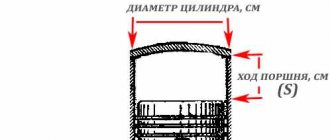
Rice. 3. Engine cylinder layout diagrams
—
Diesel. Let's consider the process of each stroke in a diesel cylinder (Fig. 7).
The first stroke is intake. The cylinder is filled with air, the oxygen of which ensures fuel combustion. The more air enters the cylinder, the greater the amount of fuel that can be burned in it and the higher the gas pressure on the piston during the working stroke (power increases).
During intake, the piston moves down, the intake valve is open and the exhaust valve is closed. The air entering the cylinder is heated when mixed with hot residual gases and from the heated parts of the operating diesel engine.
By the end of the first stroke, the air temperature reaches 40... 60 °C, and its density decreases. In addition, when moving, it encounters resistance in the diesel intake channels. For these reasons, the pressure in the cylinder is below atmospheric (0.08... 0.09 MPa).
The second stroke is compression. The piston moves up, both valves are closed. Under the action of the piston, the air is compressed 15...17 times (compression ratio e=15...17) and at the same time heats up. The pressure at the end of compression reaches 3...4 MPa, and the temperature - up to 550...600 °C, which significantly exceeds the self-ignition temperature of the fuel.
Rice. 4. Scheme of the working cycle of a single-cylinder four-stroke diesel engine: 1 - nozzle; 2 - fuel pump.
The third beat is expansion. Just before the end of the compression stroke, when the piston has almost reached c. m.t., a portion of fuel is injected into the cylinder through the nozzle. Most of it immediately ignites and burns. The gas temperature rises to 2000...2100 °C, and the pressure - to 5.5...8.0 MPa. Under this pressure of expanding gases, the piston moves down and turns the crankshaft through the connecting rod. The expansion process burns the rest of the injected fuel. As the piston moves, the gas pressure in the cylinder drops and the temperature decreases. By the end of the third cycle, the pressure decreases to 0.2...0.3 MPa, and the temperature - to 600...650 °C.
The fourth measure is release. The inlet valve is closed and the outlet valve is open. Exhaust gases are pushed out of the cylinder. The pressure of the remaining gases drops to 0.11...0.12 MPa. The temperature of the exhaust gases at the exit from the cylinder is 400...500 °C.
Then the working cycle is repeated.
Carburetor engine. In a similar way, consider the duty cycle of a four-stroke carburetor engine.
Intake stroke. The exhaust valve is closed and the intake valve is open. When the piston moves from c. m.t. down the cylinder is filled with a mixture of fuel and air. This mixture is prepared in a special device - a carburetor and is called a combustible mixture. Entering the cylinder, it is mixed with residual gases, resulting in the formation of a working mixture.
The pressure of the working mixture in the cylinder during the intake stroke, due to resistance in the carburetor, is lower than in a diesel cylinder and amounts to 0.07...0.08 MPa. The temperature of the working mixture rises from 60 to 120 °C, mainly due to the high temperature of the residual gases.
Compression stroke. During this stroke, as in a diesel engine, the working mixture, compressing, heats up. As the compression ratio increases, the pressure and temperature of the mixture increase, as well as the rate of its combustion. The result is increased efficiency and engine power. But at elevated temperatures there is a danger of premature ignition (self-ignition) of the mixture. To avoid this, the working mixture is compressed slightly (e=4...8). The pressure in the cylinder at the end of the compression stroke is 0.9...1.2 MPa, and the temperature does not exceed the auto-ignition temperature, reaching only 330 °C.
Expansion stroke. Before the end of the compression stroke, an electric charge jumps between the electrodes of the spark plug. A spark ignites the working mixture. The temperature of the burning gases reaches 2500 °C, and the pressure rises to 3.0...4.5 MPa. Under the influence of gas pressure, the piston moves downward. By the end . of the third stroke, the pressure decreases to 0.3...0.4 MPa, and the temperature - to 900...1200 °C.
The exhaust stroke occurs in the same way as in a diesel engine, but at a slightly higher gas temperature.
Comparative assessment of diesel and carburetor engines.
Compared to a carburetor (gasoline) engine, diesel has the following advantages: - diesel is more economical: per unit of work performed, due to the high compression ratio, it consumes 25% less fuel; — the fuel on which diesel operates is less dangerous in terms of fire and has a less corrosive effect on parts than gasoline.
Disadvantages of diesel: - due to the high gas pressure in the cylinders, the body and other parts that work with significant loads are heavier and larger; — to start a diesel engine, a more powerful starter or a special carburetor starting engine is required; — diesel operates with a significant excess of air, so the sizes of cylinders and other parts and assembly units are increased.
Where is it used?
4-stroke engines are used very widely in our daily life. Their power directly depends on the volume and number of cylinders. ICEs are installed in cars and airplanes, tractors and diesel locomotives. They are also used on sea and river vessels.
Power engineers also paid attention to 4-stroke power units. They are used to power stationary and emergency power generators installed in places where power lines cannot be laid or are not economically feasible.
In addition, such generators are installed at facilities where turning off the power supply is impossible (hospitals, banks, military units, etc.).
Two-stroke engines
In addition to four-stroke piston internal combustion engines, there are two-stroke ones. The principle of their operation is somewhat different from that described above. The design of such a motor is simpler. The cylinder has a window - an inlet and an outlet, located above. The piston, being at BDC, closes the inlet port, then, moving upward, closes the outlet and compresses the working mixture. When it reaches TDC, a spark forms on the spark plug and ignites the mixture. At this time, the intake window is open, and through it another dose of the fuel-air mixture enters the crank chamber.
During the second stroke, moving downward under the influence of gases, the piston opens the exhaust window, through which the exhaust gases are blown out of the cylinder with a new portion of the working mixture, which enters the cylinder through the purge channel. In this case, part of the working mixture also goes out into the exhaust window, which explains the gluttony of the two-stroke internal combustion engine.
This operating principle allows you to achieve more engine power with a smaller displacement, but you have to pay for it with higher fuel consumption. The advantages of such motors include more uniform operation, simple design, low weight and high power density. Disadvantages include dirtier exhaust, lack of lubrication and cooling systems, which threatens overheating and failure of the unit.
I like1I don't like
Types of motors
There are three types of engines found in vehicles:
- piston
- rotary piston
- gas turbine
The first version of motors is very popular. Some car models are equipped with four-stroke piston engines. This popularity is due to the fact that such units are cheaper, light in weight and suitable for use in almost all machines, regardless of production.
In simple terms, a car engine is a special mechanism that can change heat energy, turning it into mechanical energy, which makes it possible to ensure the operation of many structural elements of the car, as well as its systems.
It is not difficult to study the principle of operation of the motor. For example, piston internal combustion engines are divided into two- and four-stroke units. Four-stroke engines are called because in one operating cycle of the element the piston moves four times (stroke). More information about what bars are is written below.