Reasons for generator failure
Without specialized equipment, it is not always possible to determine the exact cause of a unit failure. But most often the problem is caused by:
- Bearing jamming . Due to drying out of the lubricant and gradual wear, the bearings jam. First, the belt usually breaks, which necessitates rebuilding the assembly.
- Winding burnout . Most often, the winding burns out due to the penetration of chemicals and salts used to sprinkle the road in winter.
- Brush wear . Graphite brushes wear out gradually, so they need to be replaced periodically. If they are not replaced in time, the unit may fail completely.
- Relay malfunction . The device is designed to prevent battery overcharging. If it malfunctions, the generator does not start.
To prevent breakdowns, scheduled vehicle maintenance should be carried out in a timely manner.
General recommendations and nuances
It often happens that the generator stops functioning only when the engine is warm. This phenomenon is due to the natural expansion of the metal with increasing temperature or a change in the properties of semiconductors (diodes) for the same reason. In this case, you should first check the functionality of the generator on a warm car, and if this does not bring results, then dismantle the device and check it after heating it with a hair dryer. In conclusion, it is worth noting that independent replacement of generator components such as stator or rotor windings and bearings in domestic conditions is advisable only if you have the appropriate equipment, tools, and experience. If it is not there, then if the battery is not charging, limit yourself to trying to replace the relay-regulator combined with the brush assembly. To do this, you don’t have to buy a new device: you can install a known good one and evaluate the result.
Check Features
When checking the generator of a VAZ 2110, 2107 and others for serviceability, the following conditions must be met:
- An accurate multimeter should be used for diagnosis.
- The normal voltage is 12 V.
- If it is necessary to replace the wiring, you must use wires with the same cross-section as the original.
- Before checking, you should check that all fasteners are connected correctly and the belt tension is correct. If necessary, the connections should be adjusted to normal, the belt should be loosened or tightened.
During the verification process it is prohibited:
- short circuit the wires;
- connect terminals that differ in purpose and parameters, connect terminal 30 or B+ to ground;
- diagnose a generator without connected consumers.
Main signs of generator malfunction
The following signs will indicate that the generator has failed or there are problems with its operation:
- constant lighting of the warning light in the form of a red battery on the dashboard, which indicates that the generator is not charging or is producing insufficient current;
- constantly discharging battery;
- interruptions in the operation of electrical equipment (lighting and alarm units, multimedia, heating and ventilation) while the engine is running;
- the appearance of a characteristic burnt smell in the cabin (engine compartment);
- excessive heating of the generator stator;
- hum (rustle, whistle) of the generator.
The appearance of such signs is a serious reason to conduct a diagnosis. To do this, it is not at all necessary to go to a service station, since it is quite possible to check the generator’s functionality on your own, especially if you have even the slightest skills in handling a car tester. But first, let's talk about the main breakdowns.
Diagnostics of the VAZ generator without removal and special tools
This is not the most reliable and reliable method, but it allows you to determine whether the generator is functioning or there are malfunctions. The use of any specialized tools, including a multimeter, is not required. There is no need to remove the generator.
To diagnose, start the engine and turn on the low beams. In operating condition, the negative terminal must be disconnected from the engine. The uniform light of the headlights and the stability of the engine stroke indicate normal operation of the generator. If malfunctions are observed or the brightness of the light changes, the VAZ generator is probably faulty; in-depth diagnostics need to be carried out.
Monitoring the performance of components
To perform this operation, it is necessary to remove the device from the vehicle and clean it of dirt. The verification procedure is as follows:
- We switch the multimeter to resistance measurement mode. We install the positive probe on terminal “30”, and the negative probe on ground. Readings close to zero indicate that the bridge or generator stator has failed.
- Positive diodes are checked by installing a positive probe on the terminal of one of the rectifier unit mounting bolts, and a negative probe on ground. Zero or close to zero instrument readings indicate that the diode bridge is faulty.
- To check the rotor, it is necessary to measure the resistance between the slip rings. In working condition it should be within a few ohms. If the resistance is near zero, then a short circuit has occurred in the winding.
The diode bridge and other faulty elements of the generator must be replaced with new ones from spare parts.
The generator is one of the most important devices in a car. Without it, the normal functioning of all blocks, components and devices that require electrical energy becomes impossible. After starting the engine, the autogenerator is turned on to power the on-board network, as well as to charge the battery. It is important to monitor and periodically check the tension of the alternator belt. Not only the service life of the belt itself, but also the normal charging of the battery depends on this. If adjusted incorrectly, the belt may slip, resulting in insufficient tension. In such a situation, the battery will not receive the necessary charge and may discharge over time (how to properly charge the battery).
If any problems arise with the power supply, the first question that faces the driver is how to check the operation of the generator. Of course, the ideal option is to carry out diagnostics at a service station. However, for example, if after a long stay in the garage the car does not start, you should not immediately look for a towing cable. Below we will describe in detail how to test a generator with a regular tester (or, in other words, a multimeter).
Read also: What is the difference between ph and pz bits
To check, we need a multimeter and, preferably, an assistant (a neighbor, a friend, or even, in extreme cases, a wife). It is worth mentioning that the tester, multimeter and avometer are actually the same device; the differences lie only in additional functions.
Sequence of actions 1. First you need to check the generator relay. Overvoltage in the vehicle's on-board network can damage various devices. To maintain the correct potential difference, a relay regulator is used. We will describe in detail how to check the generator voltage regulator. Switch the multimeter to voltage measurement mode. We start the car. We measure the voltage at the battery terminals or generator outputs. The correct value should be in the range of 14-14.2 V. Press the accelerator (here you will need the help of an assistant). The voltage value should not change by more than 0.5V. If the values of the measured parameters differ from those given, this indicates improper operation of the relay regulator. 2. Check the diode bridge, consisting of six diodes. Of these, three can be called “positive”, and three can be called “negative”. Half of the diodes have mass at the anode, and the rest at the cathode. To check, switch the multimeter to “sound” mode. If you close the contacts of the probes, a squeak will be heard. We check each diode in both directions. The squeak should only be heard in one. If the diode rings in both directions, it means it is broken and needs to be replaced. In this case, it is advisable to replace the entire bridge at once. 3. Check the generator stator. This block is made in the form of a hollow metal cylinder. The generator winding is laid inside. To check, you must first disconnect the stator leads from the diode bridge. We inspect the condition of the winding. There should be no burning or mechanical damage. We switch the tester to resistance measurement mode. We check the winding for breakdown. For this purpose, we measure the resistance between the stator housing and any of the winding terminals. The value should be as large as possible, ideally tending to infinity. If the tester shows less than 50 KOhm, it means that the autogenerator will soon fail. 4. Check the generator rotor. This unit is made in the form of a metal rod on which the winding is wound. There are rings at one end of the rod. The generator brushes slide along them. We remove the rotor and inspect the condition of the windings and bearings. We check the integrity of the winding with a multimeter. We measure the resistance between the slip rings. Its value should be on the order of several ohms. In case of a short circuit (resistance near zero) or an open circuit, the rotor must be replaced.
This instruction will help you successfully identify a fault generator in the field. The above algorithm can be successfully applied both on most modern cars and on domestic VAZ 2106, 2107, 2114, etc. The main condition is that the on-board voltage is 12V.
As you know, the generator unit is an integral part of any modern car. Thanks to this device, the battery is charged while driving, as well as powering all electrical equipment. But like any other mechanism, a generator can fail for various reasons. In this article we will tell you in what cases it is necessary to repair the generator armature and how to diagnose it.
Voltage Regulator Diagnostics
To check the voltage regulator on a VAZ 2114, 2106 car, you should perform the following steps:
- Start and warm up the engine by turning on the headlights. Warm up the engine for about 15 minutes. For diagnostics, a multimeter or voltmeter capable of taking measurements in the voltage range 0-15 V is used.
- Measure the voltage between ground and terminal 30. For most cars in normal condition, the reading will be within 13.5-14.6 V. A value less than 13 V means the unit needs to be replaced.
Purpose of the regulator relay VAZ 2107 injector and carburetor
The main purpose of the voltage regulator relay on the VAZ 2107, and any other car, is to maintain a stable and sufficient charging current for the on-board network and the car battery, as well as to level out voltage surges in the generator. Variations in the generated voltage would occur as the generator rotates at different frequencies. When the power drops below 12V, the battery stops charging, and the entire bot network no longer functions at 100%. If the voltage exceeds 16 Volts, this can lead to boiling of the battery, as well as failure of on-board devices.
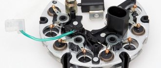
On early production VAZ cars of the carburetor type, the voltage regulator is located on the left arch of the engine compartment. Such devices are also called external, since they were installed outside the generator structure. To be more precise, a brush mechanism was installed in the generator, and control was carried out via a printed circuit board, which was installed outside the product.
Most VAZ 2107 cars of the carburetor and injection type are equipped with generators with built-in charging relays. The charging relay on such VAZ 2107 vehicles is located directly on the side of the generator opposite the pulley.
To maintain an acceptable battery charge, the alternator requires 13.6 to 14.6 volts of power. The voltage regulation circuit is carried out using an electrical circuit, which is located on a printed circuit board (chocolate board) or in the form of a single semiconductor module (tablet) with brushes. The switch located inside the generator is usually not able to adequately respond to the ambient temperature due to its location close to the running engine. The built-in relay is sometimes replaced with a three-level voltage regulator, which is due to the greater efficiency of the product due to manual adjustment of the output voltage.
How to check the charging relay on a VAZ 2107
If you suspect a faulty operation of the voltage regulator relay, then you must first check the voltage at the battery terminals with the car running. The power supply must be no lower than 13 and no higher than 14.6 Volts. The reasons for such increased or decreased voltage can be caused by the following factors:
- charging regulator malfunction;
- failure of the generator itself;
- lack of contact in the electrical connections of the battery or generator.
To check the serviceability of the chocolate bar, it is necessary to remove it from the generator. This must be done by unscrewing two bolts.
To check the serviceability of the product, you need to connect a voltmeter or test lamp, as well as an adjustable power source of 12-22 Volts. You can use a power supply with a variable resistor. The control check of the regulator relay is carried out by connecting the minus wire from the regulated source to ground or terminal “Ш”. The positive wire of the power supply must be connected to terminal “B”. A voltmeter or lamp is connected to the brushes or relay output. If the product is in good working order, then when a voltage of 12 to 14 Volts is applied to it, the light will light up or the voltmeter will show similar values. If you apply power above 16 Volts, the light should go out. If the light bulb is constantly glowing, you can judge that the product is broken. The absence of a light bulb indicates a break in the relay. In both cases, the regulator cannot be repaired, so it needs to be replaced.
How can you check the product for serviceability without removing it from the car? To do this, you need to connect a voltmeter to the battery terminals, and then start the engine. If the voltmeter readings are below 12.7V or above 14.6V, then the probability of the chocolate bar failing is 95%. Replace the product with a new one, then check the voltage.
Checking the return current
Diagnostics is carried out with the engine running at high speeds. It is necessary to measure the current consumed by the vehicle components. The probe is pressed against the wire from terminal 30 or B+.
It is necessary to turn on the electrical appliances of the car one by one and record the indicators. The resulting values should be summed. Then you need to turn on all the devices and measure the current indicator. The resulting indicator should be compared with the summed value of previous measurements. The final value should be approximately 5 A below the summed value. A higher value confirms that the node is faulty.
Typical faults
Among our compatriots there is an opinion that one of the main faults of the armature is the lack of resistance. It should be noted that the resistance is checked on the rotor winding, and the rotor, in turn, can be installed instead of an inductor, and a stator will stand instead of an armature. This is done in order to provide higher power, so the resistance can only be diagnosed at the rotor.
As for the anchor specifically, it is characterized by the following malfunctions:
- Most often, do-it-yourself repair of the generator armature is carried out as a result of wear on the slip rings;
- also, the need to repair the unit may arise as a result of failure of the shaft bearing;
- not so often, but the problem of winding short circuit still occurs.
Read also: Letter designation of the transformer on the diagram
It should also be noted that there are breakdowns that cannot be repaired:
- wear of the collector to a diameter of 8.6 cm;
- wear of keyways.
Checking the windings
First you need to visually inspect the windings. If there are no visible defects, you should use a multimeter. First you need to do the following:
- Remove the brush holder.
- Disconnect the voltage regulator.
- Clean the slip rings.
- Diagnose the winding for defects.
The resistance measurement function on the multimeter should be activated. The measurement is taken between the slip rings and the stator. In normal mode, the value will be from 5 to 10 ohms.
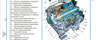
Description of the generator armature
Before checking the unit, please review the basic information. The anchor consists of the following elements:
- shaft;
- slip rings;
- brush assembly;
- collector;
- excitation winding;
- core.
Read also: Gas reducer for a gas water heater
The core of the device includes several sheets made of electrical steel, their thickness should be 0.5 mm. The core is mounted in the shaft, but if the diameter of the armature is very large, then in a cylindrical sleeve. As for the collector, it consists of copper plates, the number of which may vary depending on the design. The collector is assembled separately, after which it is pressed into the shaft using an insulating sleeve.
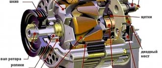
Generator unit armature device
The winding is made in the form of several sections, their ends are mounted in special protrusions on the collector plates. With the help of the latter, the winding sections are connected to each other in a serial manner, forming a closed circuit. Windings can be wave or loop. In the first, the section leads are connected to the collector unit, and they are connected to each other in a wave-like manner. In loop devices, the leads are connected to the collector plates, and they are connected to each other directly on the collector.
Operating principle
The armature of the generator unit rotates as a result of the influence of the bearing shields, as well as the bearings themselves mounted on the shaft. The shield itself, which is located next to the collector, is called the front shield. Behind this shield, on the shaft, there is an impeller designed to cool the device. To ensure air flow and also remove heat, the shields have special openings that are closed using protective covers with meshes. There are also holes in the front shield, but they are necessary for servicing the component elements of the device.
The armature of the device is connected to the network via a brush assembly. The elements themselves are located on special holders, which are fixed on the so-called fingers. These fingers are located on the traverse, which, in turn, is fixed on the front shield or frame, depending on the design. The pressure of the brush elements can be adjusted; special springs are provided for this.
The number of so-called brush fingers corresponds to the number of poles, and one half of them should have a positive polarity, and the other half should have a negative one. In general, the brush assembly divides the winding into several parallel branches; their number can also vary depending on the type of winding (video author - Volodymyr Zagryvyi / Vladimir Zagryvyi).
The on-board network of the vehicle is connected to the generator unit through a special terminal box, where there is a board with terminal marks on the windings. To ensure lifting or moving the generator unit, there is a corresponding bolt on the top of the frame. On its body there is a plate indicating the manufacturer, as well as basic technical data about the device. One of the main disadvantages of the generator device is the rather large complexity, as well as the too weak strength of the brush assembly, as a result of which the device requires periodic diagnostics and maintenance.
Diagnostics of a removed generator
To check the generator removed from the VAZ 21, you should use a multimeter in ohmmeter mode. The probes are pressed against terminal 30 and the body of the unit. If there are contaminants and strong oxides on the case, they should be removed first, as they can affect the readings of the device.
You need to measure the resistance of each generator unit in turn. Parts that do not have the required resistance have become unusable. Most of them can be replaced at home using a minimal set of tools. To replace, you need to buy the same parts as those originally installed in the generator.
Didn't find the information you are looking for? on our forum.
How to test a generator with a multimeter
The diode bridge of the generator can be checked with a multimeter, but you can also use the stand that was used to check the regulator.
But before that, first of all, without removing the rectifier bridge from the generator, connect the red wire of the tester to terminal 30 of the generator, and the black wire to the housing. Set the tester operating mode to dial (diode icon). If it is not there, then set it to 1-2 kOhm. The multimeter should show infinity. If the readings are different, the diode bridge is faulty.
Then check the current rectifiers for breakdown. Leave the positive (red) probe on terminal 30, touch the negative one to the bridge mounting bolts one by one. The multimeter display should show infinity in all cases; any others mean a breakdown.
Next, connect the positive probe to the axle mounting bolts, and the negative probe to the generator housing. In this case, the tester should also output infinity.
But in practice, such verification is most often not enough. In most cases, it is necessary to ring the generator in more detail.
Careful testing
To do this, unscrew the fastening bolts of the rectifier unit, disconnect the copper wires of the stator winding and remove the diode bridge from the generator. Now you can test each semiconductor individually. Before checking, it is advisable to rinse the stabilizer with running water using a medium-hard brush, and then dry thoroughly. For quick drying, a hair dryer is quite suitable.
Attach one of the tester probes to the diode plate, connect the second to the central terminal of each diode fixed to this plate. Then swap the probes. In one case, the multimeter should show infinity, in the other - a nominal resistance of approximately 570-590 Ohms. Rectifiers are considered faulty if:
- In the first and second measurements (when the polarity was changed), the multimeter readings are the same;
- Diode resistance is greater or less than nominal values.
Perform the same actions with the second plate of the diode bridge. If a fault is detected in one or more diodes, it will be easier to replace the entire rectifier unit. True, there are craftsmen who replace failed diodes individually, but such work requires a certain skill and dexterity.
Checking the armature and stator windings
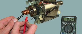
Further inspection requires completely disassembling the generator. First of all, visually check the anchor. Brush rings should not show any blackening, chipping or wear on the treadmills. Blackening and slight wear can be smoothed out with zero-grade emery cloth. Rings with deep grooves must be replaced or, if the thickness of the rings allows, turned on a lathe.
The armature winding should not clearly smell like burning. The color of the winding must be uniform and free of damage and breaks. To check the armature winding for a break, you will need a multimeter. Set the operating mode to continuity testing or resistance measurement and connect the probes to the brush rings. The winding resistance should be within 3-5 Ohms. Then leave one probe on the ring, connect the other to the body. The multimeter display should show infinity.
The generator stator is diagnosed after removal from the housing. First of all, carry out a visual inspection. There should be no visible damage to the wire or its insulation. Then connect the tester wire to the stator housing. With the second wire, touch the terminals one by one. There are only three of them. The tester must be in dialing mode. If the display shows infinity, this indicates that the stator is working properly.
Further testing consists of diagnosing the windings. The resistance of all three windings must be the same.
Before assembling the generator, you need to check and, if necessary, replace the bearings. When turning, they should not jam or make a creaking sound. This means that they are very worn out and will soon fail. Therefore, it is better to replace them immediately.
Main signs of generator malfunction
The following signs will indicate that the generator has failed or problems have arisen in its operation:
- constant lighting of the warning light in the form of a reddish battery on the dashboard, which indicates that the generator is not charging or is producing insufficient current;
- constantly discharging battery;
- interruptions in the operation of electrical equipment (lighting and alarm units, multimedia, heating and ventilation) while the engine is running;
- the appearance of a corresponding burnt aroma in the cabin (engine department);
- excess heating of the generator stator;
- rumble (rustle, whistle) of the generator.
Read also: What is measured in microns
The appearance of similar symptoms is a serious reason to conduct a diagnosis. To do this, it is absolutely not necessary to contact a service station, because you can completely check the generator for operability on your own, especially if you have even the slightest ability to use an auto tester. But first, let's talk about the main breakdowns.
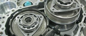
Generator bearing wear
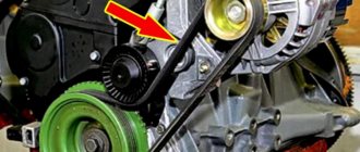
A car generator has two bearings. One of them is fixed to the rotor shaft, the second is pressed into the central part of the cover. A hum or whistle coming from the generator while the engine is running is a sure sign that one of the bearings has given up its life. A related symptom may be heating of the generator housing. If you notice these signs, hurry to replace the bearings. Otherwise, this will lead to distortion of the rotor shaft or jamming with all the ensuing consequences.
You can check the bearings by removing the alternator belt and turning its shaft by hand. If the rotor rotates easily, without jerking or play, the bearings will still serve. If rotation is difficult or there is play in the shaft, do not delay replacing the bearings.
The generator is a miniature electrical station that supplies power to many components of the car: ignition, cooling, electrical wiring. Therefore, its failure will certainly entail other malfunctions. To prevent problems, you need to have this part diagnosed and repaired from time to time.
It will be useful for any motorist to know how to check the operation of a generator in a car, but first you need to understand the possible signs of a breakdown.
Basic principles of repair
Repair of the VAZ-2106 generator is carried out according to two principles - replacing failed parts with new ones, or restoring them. The stator and rotor windings, if damaged, can be rewinded - a service common in Soviet-era car repair shops, but now few electricians will undertake such work, so more often they are replaced completely, assembled. Over time, generator drive belts stretch, lose tension and stop performing their job task - they should be replaced. Some parts can no longer be found on sale; they have to be restored, for example, by boring slip rings.
I’ll say right away that below I will not consider all types of diagnostics of the VAZ 2106 generator, but only those that I managed to do while disassembling this device. Of course, to perform these procedures you will need a special device called a multimeter. Of course, you can do everything the old way with a light bulb, but the device costs a penny, so anyone can buy it.