I'm finishing off the topic of brakes. Because if the brakes are done thoroughly, then “in a circle”, with preventive maintenance of the front and rear calipers, always the main one, and replacing the line with at least copper.
I figured out the front calipers, the rear ones - in theory, I need to replace the rubber bands with Feng Shui ATE, I'll reinstall the pipes with copper, instead of the sorcerer I'll put a brake valve in the rear circuit, and the main brake...
Perhaps, in my mind, it needs to be replaced with something nicer than stock, but first, I’ll take a look inside. After all, if everything is in order there, then let the car run in on the stock brake master cylinder, and then let the owner install something better at his own discretion, and at that time he can understand the degree of “arrival” from this replacement
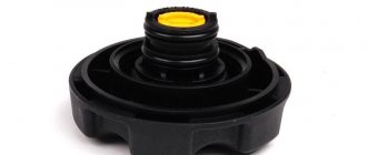
So, here is the standard GTZ VAZ-2110 from Nezhdanchik
The first step is to inspect the tank.
brrr (Off with it and in the trash,
Fortunately, a new one costs a penny even in our outback. After all, no matter how hard you try, you won’t be able to wash this sediment out because of the shape of the tank.
I'm dismantling the GTZ. Attention, you need to remove the filling towards the VUT stem. When removing the plugs to the side, you risk damaging the cuffs on the threads
Disqueri. "how does it work" ))))
Well, surprise, the inside of the GTZ is like new, without wear. Perhaps it was replaced not so long ago. The surface usually shows marks from processing, the photo does not show it (
I sand with water, sandpaper 500-800-1000-1500-2000-2500 without fanaticism
Here, now a real mirror! Again, you can’t see it in the photo(
I wash the filling, dry it, inspect and feel the rubber bands, decide to put them back, lubricate them with mounting paste and carefully assemble them.
Hydraulic brake circuit diagram
1 – front wheel brake mechanism; 2 – pipeline of the “left front–right rear brake” circuit; 3 – main cylinder for hydraulic brakes; 4 – pipeline of the “right front–left rear brake” circuit; 5 – master cylinder reservoir; 6 – vacuum booster; 7 – rear wheel brake mechanism; 8 – elastic lever of the pressure regulator drive; 9 – pressure regulator; 10 – pressure regulator drive lever; 11 – brake pedal; A – flexible hose of the front brake; B – flexible rear brake hose
The car uses a working brake system with diagonally separated circuits, which ensures high active safety of the car. One hydraulic drive circuit ensures the operation of the right front and left rear brake mechanisms, the other - the left front and right rear.
If one of the circuits of the service brake system fails, the second circuit is used to stop the vehicle with sufficient efficiency.
The hydraulic drive includes a vacuum booster 6 and a dual-circuit pressure regulator 9 for the rear brakes.
The parking brake system is driven by the brake mechanisms of the rear wheels.
Brake system VAZ 2110 - diagram
For better or worse, all Tolyatti models suffer from the same diseases. The perestroika virus brought them to the plant back in the 80s, along with the VAZ 2108, and since the genetics of the cars did not change, the diseases were the same. The VAZ 2110 is no exception. A nice replacement for the eights and nines appeared on the assembly line about 20 years ago, almost completely repeating the design of the front-wheel drive VAZ first-borns. The same applies to the brake system of the tenth family, which we will wash the bones with today.
Content:
Vacuum booster
1 – vacuum booster housing;
2 – amplifier housing cup; 3 – rod; 4 – adjusting bolt; 5 – rod seal; 6 – sealing ring of the master cylinder flange; 7 – diaphragm return spring; 8 – amplifier pin; 9 – tip mounting flange; 10 – valve; 11 – hose tip; 12 – diaphragm; 13 – amplifier housing cover; 14 – sealing cover; 15 – piston; 16 – protective cover of the valve body; 17 – air filter; 18 – pusher; 19 – pusher return spring; 20 – valve spring; 21 – valve; 22 – valve body bushing; 23 – rod buffer; 24 – valve body; A – vacuum chamber; B – atmospheric chamber; C, D – channels The rubber diaphragm 12 together with the valve body 24 divides the cavity of the vacuum amplifier into two chambers: vacuum A and atmospheric B. Chamber A is connected to the engine inlet pipe through the check valve of the tip 11 and a hose.
The 24 valve body is plastic. At the exit from the cover, it is sealed with a corrugated protective cover 16. The valve body contains the main cylinder drive rod 3 with a support sleeve, rod buffer 23, valve body piston 15, valve assembly 21, pusher and valve return springs 19 and 20, air filter 17 , pusher 18.
When you press the pedal, the pusher 18, the piston 15, and after them the valve 21 move until it stops against the seat of the valve body. In this case, cameras A and B are separated. As the piston moves further, its seat moves away from the valve and through the resulting gap, chamber B is connected to the atmosphere. The air entering through filter 17, the gap between the piston and the valve and channel D creates pressure on the diaphragm 12. Due to the difference in pressure in chambers A and B, the valve body moves along with the rod 3, which acts on the piston of the main cylinder.
When the pedal is released, valve 21 moves away from the body seat and through the resulting gap and channel C of chambers A and B communicate with each other.
Master brake cylinder. Purpose, device
The main element of the hydraulic drive is the brake master cylinder (MBC). It is thanks to him that the mechanical action is converted into brake fluid pressure. It also separates the entire braking system along its contours, which is very important.
The main condition for the normal functioning of the hydraulic drive is the tightness of the system. If the pipelines break down due to a leak, the entire system will stop working. To avoid a complete failure of the system, it was divided into two circuits independent of each other. Each of them combines two brake mechanisms. As a result, if the pipeline of one of the circuits is damaged, the second remains sealed and the mechanisms to which it is connected continue to perform their function. And although the efficiency of the system decreases, the car still retains the ability to brake.
The design and operating principle of a dual-circuit gas turbine engine are quite interesting. And although they may differ in appearance, the internal structure of all main cylinders is almost the same.
There is a cavity made inside the body and channels for connection with pipelines (leading to the brake mechanisms) and a reservoir from where fluid is supplied. In this cavity there are two pistons installed one behind the other. They act on the liquid. To ensure that the pistons return to their original position after the pedal is released, they are both spring-loaded. Moreover, the spring stop of the first piston is the second one. The spring of the second piston rests against the end wall of the housing cavity.
Since each of the pistons is responsible for supplying liquid only to its own circuit, the entire cavity is divided into two chambers (one is located between the pistons, the second is between the piston and the housing wall). To ensure the tightness of each of them, rubber sealing elements are installed on the pistons.
Each of the working chambers is connected to the tank by two channels - compensation and bypass. Thanks to them, the amount of fluid in the system is replenished and the formation of vacuum and air in the system is prevented when the pedal is released. Also, two pipelines are connected to the chamber, each of which leads to its own brake mechanism.
Video: Brake master cylinder
The tank can be attached directly to the GTZ body or be remote (in this case it is connected to the cylinder by pipelines). The liquid from it is supplied to both circuits, but there is a partition inside the tank that separates the liquid between the circuits. This is necessary so that in the event of a depressurization of the system, all the liquid does not leak out.
Pressure regulator drive
1 – pressure regulator; 2, 16 – pressure regulator mounting bolts; 3 – bracket for the pressure regulator drive lever; 4 – pin; 5 – pressure regulator drive lever; 6 – axis of the pressure regulator drive lever; 7 – lever spring; 8 – body bracket; 9 – pressure regulator mounting bracket; 10 – elastic lever of the pressure regulator drive; 11 – earring; 12 – earring bracket; 13 – washer; 14 – retaining ring; 15 – bracket pin; A, B, C – holes
Pressure regulator
1 – pressure regulator housing;
2 – piston; 3 – protective cap; 4, 8 – retaining rings; 5 – piston sleeve; 6 – piston spring; 7 – body bushing; 9, 22 – support washers; 10 – sealing rings of the pusher; 11 – support plate; 12 – pusher bushing spring; 13 – valve seat sealing ring; 14 – valve seat; 15 – sealing gasket; 16 – plug; 17 – valve spring; 18 – valve; 19 – pusher bushing; 20 – pusher; 21 – piston head seal; 23 – piston rod seal; 24 – plug; A, D – chambers connected to the main cylinder; B, C – chambers connected to the wheel cylinders of the rear brakes; K, M, N – clearances The pressure regulator regulates the pressure in the hydraulic drive of the brake mechanisms of the rear wheels depending on the load on the rear axle of the car. It is included in both circuits of the brake system and through it brake fluid flows to both rear brake mechanisms.
Disassembly
To replace and repair a damaged master brake cylinder, you need to remove it from the VAZ 2110; to do this, you should carry out several steps:
- Carefully disconnect all pipelines from a part such as the main cylinder;
- Disconnect the block equipped with wires from the emergency brake fluid indicator. They are connected by terminals;
- It is necessary to prevent fluid leakage and contamination of the mechanism; to do this, it is necessary to cover the openings of the unit and pipelines;
- Next, you need to remove it along with the tank; to do this, unscrew the fastening nuts that secure it to the vacuum type amplifier;
- After the VAZ 2110 fluid level sensor is removed, you need to drain all the brake fluid from the cylinder and basque;
We can only add to this that if there is no great need, you should not remove the reservoir from the master cylinder. To completely disassemble it, you need to remove the tank. Assemble and then install in place in exactly the reverse order.
Before you begin assembling the unit, all components must be washed with purified brake fluid or isopropyl alcohol. After this, everything must be carefully dried using a compressor, and then each of them must be wiped with a dry, clean cloth.
The main thing is not to get mineral oils directly or indirectly on the components; it is also dangerous for the front components of the main type brake cylinder, kerosene and diesel fuel to get on them.
If you find that the brake pedal has increased travel, it is recommended to bleed the brakes. The intricacies of the procedure can be found in this article:
Master cylinder with reservoir
1 – main cylinder body; 2 – low pressure sealing ring; 3 – drive piston of the “left front–right rear brake” circuit; 4 – spacer ring; 5 – high pressure sealing ring; 6 – pressure spring of the sealing ring; 7 – spring plate; 8 – piston return spring; 9 – washer; 10 – locking screw; 11 – drive piston of the “right front–left rear brake” circuit; 12 – connecting sleeve; 13 – tank; 14 – brake fluid emergency level sensor; A – gap
Master cylinder with sequential pistons. A tank 13 is mounted on the master cylinder body, in the filler neck of which a sensor 14 for emergency brake fluid level is installed. The high pressure O-rings 5 and the rear wheel cylinder rings are interchangeable.
Algorithm for removing the GTZ VAZ 2108
- Remove the reservoir cap from the brake fluid and brake fluid, remove the reservoir from the brake fluid, using something wooden to remove it from the seat.
- To prevent brake fluid from getting on electrical wiring and other elements, you need to place some kind of rag under the turbocharger. After this, use a special key, which eliminates the possibility of “licking” the edges, to turn off the pipes.
Key for removing the turbocharger
Be careful!
TJ is toxic, leaves stains on clothes, plastic, rubber. It is better to leave marks on the tubes with paint or a marker.
Front wheel brake
1 – brake disc;
2 – pad guide; 3 – caliper; 4 – brake pads; 5 – cylinder; 6 – piston; 7 – pad wear indicator; 8 – sealing ring; 9 – protective cover of the guide pin; 10 – guide pin; 11 – protective casing The front wheel brake mechanism is disc, with automatic adjustment of the gap between the pads and the disc, with a floating caliper and a brake pad wear indicator. The bracket is formed by a caliper 3 and a wheel cylinder 5, which are tightened with bolts. The movable bracket is bolted to pins 10, which are installed in the holes of the guide 2 of the pads. Lubricant is placed in these holes, rubber covers 9 are installed between the pins and the pad guide. Brake pads 4 are pressed against the grooves of the guide by springs, the inner one of which has a lining wear indicator 7.
A piston 6 with a sealing ring 8 is installed in the cavity of the cylinder 5. Due to the elasticity of this ring, the optimal gap between the pads and the disk is maintained.
Repair of the brake system of VAZ 2110
Most often, repair and maintenance of brakes of the tenth family occurs during planned replacements of consumables - pads, brake discs, cuffs and seals. In this case, it is necessary to evaluate the degree of wear not only of the brake pads themselves, but also of the discs and drums. Often, no attention is paid to their condition until the pads literally begin to whistle. The normal service life of brake pads is up to 60 thousand, depending on the degree of hardness. But if the disc is worn out, the pad wears out much faster. Before changing pads, it is imperative to check the condition of the discs and drums, and, if necessary, sharpen or grind their surface.
Wheel cylinder
1 – block stop; 2 – protective cap; 3 – cylinder body; 4 – piston; 5 – seal; 6 – support plate; 7 – spring; 8 – crackers; 9 – thrust ring; 10 – thrust screw; 11 – fitting; A – slot on the thrust ring
The rear wheel brake mechanism (Fig. Rear wheel brake mechanism) is drum-type, with automatic adjustment of the gap between the shoes and the drum. The automatic clearance adjustment device is located in the wheel cylinder. Its main element is a split thrust ring 9 (Fig. Wheel cylinder), installed on the piston 4 between the shoulder of the thrust screw 10 and two nuts 8 with a gap of 1.25–1.65 mm.
The thrust rings 9 are inserted into the cylinder with tension, providing a shear force of the ring along the cylinder mirror of at least 343 N (35 kgf), which exceeds the force on the piston from tension springs 3 and 7 (see Fig. Brake mechanism of the rear wheel) of the brake pads.
When, due to wear of the linings, the gap of 1.25–1.65 mm is completely removed, the shoulder on the thrust screw 10 (see Fig. Wheel cylinder) is pressed against the shoulder of the ring 9, as a result of which the thrust ring moves after the piston by the amount of wear. When the braking stops, the pistons are moved by the force of the tension springs until the cracks stop against the shoulder of the thrust ring. This automatically maintains the optimal clearance between the pads and the drum.
Malfunctions of the brake system of the VAZ 2110
The main malfunctions of the brake system of the VAZ 2110 can safely include the following set:
- brake fluid leakage through brake hoses;
- the brake pedal falls off;
- airing of the line due to a violation of the tightness of the connections or a fall
- brake fluid level in the reservoir;
- overheating of the front brakes, as a result of which the brake discs fail;
- malfunction of the vacuum brake booster.
There are not many malfunctions, but they do not bring joy. Most often, all fluid leaks occur due to the fact that the brake hoses of the front calipers are worn out. Whenever possible, they should be monitored from time to time. It is also common for the brake pedal to fail due to a defect or wear of the brake booster diaphragm. It is easy to identify such a breakdown. When the engine is off, the pedal will have normal travel, but it will be stiff. And when you start the engine, the pedal slowly goes to the floor. It should be taken into account that the depressed pedal moves 5-10 mm when starting the engine is a normal phenomenon on all VAZ cars with a vacuum booster. If the pedal fails, then you can safely make a claim against the amplifier’s diaphragm membrane. Most likely it is broken or simply worn out.