01/26/2022 13,592 VAZ 2109
Author: Ivan Baranov
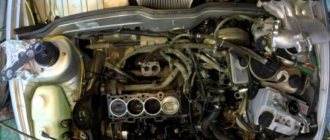
Modern cars are mostly equipped with an internal combustion engine. In order to cope with various unforeseen situations on the road, you need to know the structure of the machine. The article describes the operating procedure of the VAZ 2109 cylinders, as well as possible malfunctions in the operation of the power unit.
[Hide]
How to check high-voltage wires of a VAZ 2110
how to check the high-voltage wires of the ignition system.
Diagnosis of misfires on VAZ cars.
High-voltage wires of engine 2112 (1.5i 16v) - check and replacement.
Ignition coil with wires VAZ 2110 BU.
High voltage wires 8kl. injector VAZ 2111 SLON.
procedure for connecting high-voltage wires VAZ 2110 injector Do it yourself.
AT 320N Wiring for VAZ 2110 (1.5i 16V).
Removal, installation and repair of Lada Granta ignition coils
How to install high-voltage wires correctly.
Checking and replacing spark plugs of the VAZ 2110 Lada.
High-voltage wire VAZ-2111 dv.1.5 SLON set.
ignition module 2112-3705010-02 -2110.
2111-3707080 SLON High-voltage wire VAZ-2110 SLON kit (packed)…
Spark plugs for VAZ 2110 8 valves.
How to check the high-voltage wires of a car?
VAZ 2110 (VAZ 2110) – Replacement of I/O ignition wires.
Diagram, procedure for connecting VAZ high-voltage wires.
The numbering of the wires is marked on white rings, and the qi numbers are cast on the module...
VAZ 2110 (VAZ 2110) – Replacement of I/O ignition wires.
Replacement of high-voltage wires and installation of the left rear view mirror, i.e...
Comment on Removing and disassembling the ignition sensor-distributor of the VAZ-2110.
High-voltage wire VAZ-2112 V16 silicone set, RF.
Compression check
After checking the compression, you can breathe a sigh of relief or worry, since the cost of the repair depends on the result.
Impaired compression often causes the presence of oil in the VF, and also causes a number of other problems.
Compression check
To work you will need:
- Compressometer;
- A rag in oil, which you will use to determine the compression stroke;
- Adapter for spark plug holes. It is used when checking the combustion chamber for leaks;
- Compressor.
Now let's start checking.
- Warm up the engine to operating temperature, then turn off the fuel supply.
- In the case of a carburetor, you need to remove the hose, clamp or squeeze it with something, or lower it into a container.
- If you have an injector, remove the fuel pump fuse, start the engine and let it run. As soon as the fuel in the fuel rail runs out, it will stall on its own.
- Disconnect the ignition system by removing the center wire from the distributor (on the carburetor). The crankshaft position sensor at the injector must be disconnected.
- Remove all debris from the spark plug wells so that it does not end up inside the cylinders. Unscrew the spark plugs.
- Insert the compression gauge fitting while an assistant starts the engine. The starter should rotate the engine until the pressure gauge needle stops in one position.
- By analogy, measurements are carried out on each cylinder, the results are recorded on paper.
- To calculate ideal compression, use the formula - 1.2 * Compression ratio.
See your owner's manual for the compression ratio of your engine. Please also note that measurements may have some error.
Car ignition installation procedure
Construction machines and equipment, reference book
Category:
Car device
The ignition is installed to ensure normal operation and obtain the greatest power and efficiency of the engine. It is carried out if the ignition distributor is removed from the engine or if the ignition timing is not set correctly.
Installing the ignition on a GAZ-66 car in case of removing the ignition distributor is carried out in the following order: 1. Set the piston of the first cylinder to a position 4° before TDC on the compression stroke according to the marks on the flywheel and the arrow in the flywheel housing window. To determine the compression stroke, it is necessary to unscrew the first cylinder.2. Set the octane corrector to “O”, check the condition of the breaker contacts and the gap between them, and adjust if necessary.3. Insert the ignition distributor so that the vacuum regulator is directed upward, and by turning the drive shaft, insert the shank into the groove of the drive shaft.4. Using a screw, secure the fixed octane corrector plate to the drive housing and connect the wire to the distributor terminal.5. Loosen the nut securing the drive housing holder and turn the distributor housing to set the breaker contacts to the beginning of opening. It is better to determine the beginning of the opening of the contacts by the control light, for which connect it between the breaker terminal and ground (on cars with a contact-transistor ignition system, connect it between the unmarked terminal of the ignition coil and ground). Then turn on the ignition and, if the control lamp lights up, turn the distributor housing clockwise until the lamp goes out, and then slowly turn the distributor housing counterclockwise until the lamp lights up. In this case, the ignition distributor rotor must be located against the electrode with the number “1”.6. Tighten the nut securing the drive housing holder.7. Replace the distributor cap and connect the wire from the side electrode of the cap with the number “1” to the spark plug of the first cylinder. Connect the remaining wires to the spark plugs in the order of engine operation (1-5-4-2-6-3-7-8), following from electrode I clockwise.8. Connect the tube to the vacuum regulator.9. Check the correct installation of the ignition with the mileage of the loaded vehicle. To do this, on a flat road with a vehicle speed in direct gear of about 30 km/h, sharply press the throttle pedal all the way and hold it in this position until the vehicle speed reaches 60 km/h.
Rice. 1. Determination of TDC and setting the ignition on the ZIL-130 (ZIL-131) engine: 1 - crankshaft pulley; 2 — ignition installation indicator; I, II - ignition advance by 0° and 9°
If the ignition is installed correctly, during acceleration of the car, a slight detonation will be heard, which disappears when a speed of 40-50 jcm/h is reached. In case of strong detonation, it is necessary to move the index arrow of the upper plate of the octane corrector towards the “—” sign, and in the absence of light detonation, the index arrow must be moved towards the “+” sign. After adjusting the ignition timing, check the engine operation again using the vehicle's mileage.
The ignition installation on ZIL-131 and Ural-375D vehicles has features, the main ones of which are the following: 1. The piston of the first cylinder is installed in the compression stroke 9° before TDC with a contact ignition system and 6° before TDC with a transistor ignition system. Marks for setting the ignition are made on the engine crankshaft pulley (hole) and on the ignition setting scale.2. With a transistor ignition system, instead of installing contacts at the beginning of opening, it is necessary to rotate the distributor body to align the installation (red) marks on the rotor and stator of the pulse sensor and tighten the bolt securing the octane corrector plate to the distributor body.3. The spark plug wires are numbered, which makes it easier to distribute them among the cover sockets.4. On the Ural-375D vehicle, the ignition installation is not checked by mileage.
Read more: Main malfunctions of the ignition system and methods for detecting the causes of malfunctions
Category: – Car structure
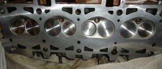
Block head and timing device
All front-wheel drive cars of the VAZ family, be it 2109, 2110 or 2114, have one cylinder head, common to all cylinders. They are mounted to the block using ten screws. During installation, a metal gasket is placed under it. This gasket is for single use and cannot be reused. There are five camshaft bearings at the top of the cylinder head.
The camshaft of the engine of the VAZ-2109 car has the index 21083. Some engines are equipped with 2110 or 2111 shafts; their design is slightly different from 21083, which allows for an increase in engine power. The shaft is cast from cast iron, there are five supports and eight cams on it that open the valves. It is driven by a toothed belt from the crankshaft pulley. The shafts can be correctly installed relative to each other using the alignment lug on the rear timing belt cover and the marks on the drive gears and flywheel.
Seats are pressed into the cylinder head, as well as valve guides. On the inside of the bushings there are grooves for supplying lubricant; the bushings are closed on top with oil deflector caps.
The valves are made of steel, and the intake head is made of heat-resistant steel. They are mounted obliquely in one row. The inlet valve has a larger diameter than the outlet valve. The gaps between the valves and camshaft cams are adjusted using shims that have increased wear resistance.
Pushers are metal cups moving in the cylinder head holes. To improve wear resistance, the surface in contact with the ends of the valve stems is cemented.
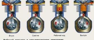
The principle of operation of a four-stroke power plant
You can understand why it is important to connect high-voltage wires correctly if you study the principle of operation of the power plant. The VAZ-2109 carburetor or injector operate on approximately the same principle, since both power plants are four-stroke
- First, the cylinder volume is filled with the fuel mixture and exhaust gases. This process is called "inlet".
- The engine then goes into compression. With it, the valves are closed, and the crankshaft and connecting rod move the piston upward. The mixture of fuel and air is transferred to the combustion chamber.
- During the expansion stage, the ignition is switched on and a spark appears. It ignites the fuel mixture, resulting in the formation of gases. They put pressure on the piston, causing it to move down. This force is transmitted through the connecting rod to the crankshaft.
- The process is completed by the “release” of exhaust gases through the exhaust system.
Compression check
After checking the compression, you can breathe a sigh of relief or worry, since the cost of the repair depends on the result.
Impaired compression often causes the presence of oil in the VF, and also causes a number of other problems.
Compression check
To work you will need:
- Compressometer;
- A rag in oil, which you will use to determine the compression stroke;
- Adapter for spark plug holes. It is used when checking the combustion chamber for leaks;
- Compressor.
Now let's start checking.
- Warm up the engine to operating temperature, then turn off the fuel supply.
- In the case of a carburetor, you need to remove the hose, clamp or squeeze it with something, or lower it into a container.
- If you have an injector, remove the fuel pump fuse, start the engine and let it run. As soon as the fuel in the fuel rail runs out, it will stall on its own.
- Disconnect the ignition system by removing the center wire from the distributor (on the carburetor). The crankshaft position sensor at the injector must be disconnected.
- Remove all debris from the spark plug wells so that it does not end up inside the cylinders. Unscrew the spark plugs.
- Insert the compression gauge fitting while an assistant starts the engine. The starter should rotate the engine until the pressure gauge needle stops in one position.
- By analogy, measurements are carried out on each cylinder, the results are recorded on paper.
- To calculate ideal compression, use the formula - 1.2 * Compression ratio.
See your owner's manual for the compression ratio of your engine. Please also note that measurements may have some error.
What you need to know about verification
- If the indicator is 12 atmospheres, this indicates that your engine is almost in perfect condition.
- When checking the compression on a cold engine, the compression readings will be significantly lower. Perform the test only on the engine at operating temperature.
- If the battery is partially discharged, the test data will also not be accurate.
- The increase in compression occurs due to the combustion of oil in the cylinders.
Finding the ignition moment in the ignition
On engine 402, ignition adjustment occurs according to the following algorithm and order:
- The crankshaft occupies a spatial position corresponding to 5 degrees of advance in ignition of the fuel mixture;
- This position can be easily achieved by aligning the mark on the pulley with the recess on the motor block;
- The coincidence means that the power plant has marked the end of a full piston stroke.
With the distribution sensor removed, adjustments are made as follows:
- I remove the spark plug from the head of the combustion chamber of the cylinder, which is listed as No. 1 in the order of fuel ignition;
- I cover it with a sheet of paper and turn the engine crankshaft;
- The air pushed out by the piston blows off the sheet, which indicates that it has reached the vertical maximum, from which the stroke begins;
- Then, using the keys, I set the octane corrector scale to 0.
Engine crank mechanism
The design of the cylinder block of the VAZ-2111 engine is identical to block 21083. It is cast from cast iron, the cylinder diameter is 82 mm, and if the piston group is replaced, it can be increased by:
Crankshaft
The crankshaft is located at the bottom of the block and rotates on five main bearings that have removable covers, which are secured to the block with bolts. The covers are not interchangeable and are marked with marks on the outside. The middle support of the main bearing has slots into which support half-rings are installed, eliminating axial displacement of the crankshaft. The front half-ring is made of an alloy of steel and aluminum, the rear half-ring is made of cermet. If play in the crankshaft appears, the half rings must be replaced.
The bearing shells - support and connecting rod - are thin-walled, made of steel-aluminum alloy. There are grooves on the inside of all the upper main bearings, with the exception of the third bearing bearing.
The design of the crank (engine crankshaft) is as follows: it is cast iron, has four connecting rods and five main journals. Eight counterweights are cast together with the shaft. Channels are drilled inside the shaft, closed with plugs and having a dual purpose:
- they supply oil to the connecting rod journals from the main ones;
- they clean the oil, since centrifugal force throws all mechanical impurities that are not retained by the filter towards the plugs.
High voltage wires. Test
High voltage wires
Many car enthusiasts are interested in the question: “which high-voltage wires are better?” And few of them find the correct answer. In this article we will try to find out the answer to this question and find out the results of the high-voltage wire test.
One well-known auto magazine has already conducted a similar test, but this test is focused on carburetor cars. Do not forget that injection and carburetor engines have different requirements, for example, carburetor wires have a lot of radiation, which will interfere with the electrics of the injection engine. In this article we will test high-voltage ignition wires for injection engines, which are equipped in most of our cars.
Let us remember the Soviet-era GOST for high-voltage wires (GOST 14867-79). Here are the main points of the content of the standard:
Terms of Use:
- climatic version O according to GOST 15150-69;
- operating temperature from minus 60 to 110°C;
- The wire is resistant to oil, gasoline, ozone, mold, and does not propagate fire.
Let us immediately note that the conditions and situation in the world have changed greatly since 1979.
Reliability of wires according to the following criteria:
- Active resistance.
- Breakdown voltage (at least 40 kV according to GOST).
- Electromagnetic field level.
- Price.
The test involves complex and inaccessible equipment:
- multimeter MY68;
- universal breakdown installation UPU-1M;
- electromagnetic radiation level meter P3-31.
Our test involves high-voltage (HV) wires from the following companies:
- Slon.
- Ween.
- Cezar.
- Horse.
- Tesla.
- Finwhale.
Let's take a closer look at the candidates:
SLON
According to our information, SLON high-voltage wires have been installed from the factory on domestic cars for three years now. Sellers in auto parts stores also say the same. The resistance of wires 1 to 4 is: 4.24-4.74-5.19-7.60. They passed the breakdown test at 40 kV. The price for high-voltage SLON wires is approximately 480 rubles.
Ween
The country of origin is Belgium. They have resistance from cylinders 1 to 4: 6.17-6.57-7.52-9.89 kOhm. The breakdown occurred at around 35 kV. The price for Ween high-voltage wires is approximately 260 rubles.
Cezar
Country of origin - Russia. Resistance from cylinders 1 to 4 is: 3.10-3.53-4.23-5.34 kOhm. Passed a breakdown test at 40 kV. Estimated cost: 450 rubles.
Tesla
The country of origin is the Czech Republic. Tesla high-voltage wires have a resistance from cylinders 1 to 4 of 3.27-4.16-5.02-6.26 kOhm. Passed the breakdown test up to 50 kV. The cost of Tesla high-voltage wires is 450 rubles.
Horse
The country of origin is Russia. The resistance of the wires is 3.15-3.90-4.09-6.24 kOhm. The breakdown test passed up to 40 kV. The price for high-voltage Horse wires is approximately 360 rubles.
Finwhale
Country of origin: Germany. The resistance of wires of this brand is: 1.95-2.18-2.60-3.42 kOhm. The breakdown test has been passed (50 kV). The price for Finwhale high-voltage wires is 570 rubles.
Absolutely all the wires we examined are suitable for operation in Russian realities:
- all wires are silicone;
- soft;
- withstand temperature changes from -40 to +100 degrees Celsius;
- as for electromagnetic radiation, all wires are within the permissible limits;
Let's summarize a little and enter the data into the table. Based on the table, you can find out how much high-voltage wires cost and what characteristics they have.
Comparison table of high voltage wires
Do not forget that each engine is designed for certain wires, and not every wire will ensure its normal operation. Choose your GDP wisely!
Useful articles:
https://youtube.com/watch?v=K2nNmBjJOyo
Purpose of the distributor cover
The design of the ignition distributor cap (aka distributor) has remained and remains virtually unchanged throughout the entire history of the use of this device as part of the ignition system of gasoline engines:
- On most ignition caps, the contacts for the spark plug wires are marked with numbers that correspond to the serial numbers of the corresponding cylinders
- In addition to protecting the distributor mechanism itself from moisture and dirt, it also serves the purpose of alternating the supply of high-voltage current from the ignition coil winding through high-voltage wires to the spark plugs
- It is because of this narrow specialization that the distributor cap has undergone almost minimal changes along the evolution of all car systems
Let's look at the design and operating principle of this much-needed part.
The distributor cap is a molded part made of non-electrically conductive material (insulator) that has the following device:
- Metal contacts are pressed into this part - these are the side and central electrodes
- The number of side electrodes strictly corresponds to the number of engine spark plugs (but not cylinders, do not forget that there are engines in which there is more than one spark plug for each individual cylinder); the distributor cover on the VAZ 2109 in our case has four side electrodes
- A high-voltage (armor) wire coming from the ignition coil is connected to the central electrode from the outside
- To the side electrodes - high-voltage (armor) wires going to the spark plugs
- Inside the cover itself there is a central contact equipped with a terminal that has a spring-loaded contact element (“carbon”), which transmits voltage to the central (main) contact of the distributor rotor (ignition distributor)
Schematic design of the lid
- When installing the cover on the distributor body, it is important to take into account not only the order in which the armored wires are connected, but also the orientation of the cover in relation to the “nose” of the runner is also important
- The ignition distributor cap is attached to the distributor body using latches or screws (the distributor cap on the VAZ 2109 is secured with screws)
- To prevent the formation of condensation under the lid, it has a special ventilation hole
Features of device operation
The “sore spot” of the distributor cover and rotor (ignition distributor) are the electrodes pressed into it:
- The reason is simple - there is no direct contact between these electrodes and the central electrode on the slider, so a spark jumps when they approach through the air, which causes the side electrodes to char rather quickly
- In order for the distributor cap to function reliably, it must be kept clean both outside and inside.
- It is necessary to periodically check the condition of the electrodes contained in it.
- If carbon deposits or oxides appear on them, clean the contacts of the VAZ 2109 distributor cover with a flat file
- It is not recommended to use sandpaper due to the high probability of abrasive particles getting into the distributor mechanism
- In addition, you should carefully monitor the external condition and mobility of the central contact (“coal”) of the cap electrode
Distributor cap as an anti-theft device
Due to the increasing number of car thefts, some “savvy” owners began to use the distributor cap as an additional anti-theft device:
- By removing the cover, which can be removed quite easily, you will make it more difficult for a thief who wants to steal your car.
- Firstly, the car simply won’t start without it.
- Secondly, even if he finds or has a cap with him, having removed the armored wires, you did not mark their connection order, connecting at random it is difficult to quickly achieve correct operation of the ignition
The order of operation of all cylinders in the VAZ 2109 engine description, photo and video
Modern cars are mostly equipped with an internal combustion engine. In order to cope with various unforeseen situations on the road, you need to know the structure of the machine. The article describes the operating procedure of the VAZ 2109 cylinders, as well as possible malfunctions in the operation of the power unit.
Operating procedure
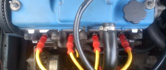
Often when repairing an engine, it becomes necessary to disconnect high-voltage wires. Some drivers, after disconnecting the wires, do not remember the order in which they were installed. As a result, there may be confusion with the wires, and if they are connected incorrectly, the car will not start. To avoid an unpleasant situation, you need to know how the internal combustion engine operates.
The principle of operation of the power unit is based on such a property of gases as the ability to expand when heated. A standard four-cylinder engine operates in 4 strokes:
- During the first stroke, the air-fuel mixture and part of the exhaust gases are “injected”. This mixture completely occupies the volume of the cylinder.
- In the second cycle, the “compression” process occurs. In this case, the valves are closed, and the piston moves upward due to the movement of the crankshaft and connecting rod. The working mixture fills the combustion chamber.
- On the third stroke, called “expansion,” a spark appears thanks to the spark plugs, which ignites the working mixture. The expanding gases exert pressure on the piston and force it to move downward. Then, thanks to the connecting rod, the crankshaft begins to move.
- On the fourth stroke, the process of “release” of exhaust gases is carried out. Through the exhaust valves they enter the exhaust system of the VAZ 2109.
In order for the operation of a multi-cylinder engine to be smooth and the crankshaft not to experience uneven loads, it is necessary that the work processes be carried out in a certain order.
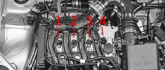
There are different schemes that determine in what sequence the cylinders will function. The VAZ 2109 uses the following scheme: 1-3-4-2. The cylinders are numbered starting from the front cover of the power unit.
If we imagine the working process of the engine through the cylinders, then the order of operation is as follows:
- In the first cylinder, an upward movement occurs, the working process takes place: the air-fuel mixture burns, the gases expand.
- In the third, a “compression” process is carried out, in which the piston moves upward.
- The fourth receives the working mixture as the piston moves downwards, thus carrying out the “injection” process.
- In the second, the piston moves upward, while the exhaust gases exit through the exhaust valves.
Possible causes of failure
During the operation of the internal combustion engine, various malfunctions are possible. To detect them, you should perform the following sequence of actions:
- First you need to start the car. The engine should idle. At this time, you should listen to what sounds are coming from the exhaust pipe. If you hear regular popping noises, then one of the cylinders is faulty. The cause may be faulty spark plugs and lack of spark. The malfunction can also be caused by a large amount of incoming air or insufficient compression in the cylinder.
- It is necessary to inspect the candles. If there is carbon deposits, moisture or oxidation, you need to clean it. Check the gap between the electrodes, which should be 0.8 - 0.9 mm.
- Replace all spark plugs, regardless of their appearance and vehicle mileage.
- If there are irregular emissions, you need to inspect the high-voltage wires.
There should be no traces of oxidation on their tips, and the insulation should not be damaged. If defects are found, the wire should be replaced. Wires connecting to the coil - The gas distributor cap should be inspected. There should be no soot or cracks on it. The carbon contact should be checked for damage and wear.
- The rotor needs to be inspected. It must be solid and have no signs of burnout. All parts with defects must be replaced.
- The pressure in the cylinders is allowed to be no lower than 1.1 MPa, and the compression difference should not exceed 0.1 MPa. If the indicators do not correspond, engine repair is necessary.
Engine workflow through cylinders
The cylinders are activated as follows:
- In the first there is an upward movement. The gases expand and the mixture of air and fuel burns.
- In the third, to carry out the compression procedure, the piston rises.
- In the fourth, “injection” occurs - the piston moves down and at the same time a mixture of air and gasoline enters the cylinder.
- In the second cylinder, the piston rises and takes the upper position so that gases escape through the valve system. After which the exhaust gases are removed from the power unit.
Based on the principle of operation of the cylinders, their activation diagram looks like this: 1-3-4-2. It is important to connect them correctly so that the cylinders work in that order.
Frequency of adjustment work
The frequency of adjustment directly depends on driving style, vehicle load, and the correct use of a particular brand of gasoline. If the car is operated without harsh driving and is not heavily loaded, then the adjustment period is 15 thousand km; if the vehicle is used for cargo transportation, then 10 thousand km. Well, if the wrong type of fuel is used for the cylinder head (cylinder head), regardless of the settings of the ignition system, the valve clearances are adjusted after 5-6 thousand kilometers.
The GAZ family of cars is equipped with the following internal combustion engine models: 402, 405 and 406 engines. The 402 engine is installed on both the Volga and GAZelle. Now it’s worth moving on to the indicators of acceptable standards.
Signs of a faulty contact system
As we know today, there are distributors with non-contact and contact spark generation systems, let’s begin to understand the contact system. If you have a contactless device, then the instructions are a little lower for you:
- Symptoms that appear in the contact system are usually caused by either a change in the gap between the contacts or their contamination
- Since the performance of the contact distributor (see Design of the VAZ 2109 distributor: the difference between contact and non-contact ignition systems and ignition timing adjustment), the condition of its contacts has a huge impact, unlike a device that has a contactless system
- The condition of the contacts should be checked every 10,000 kilometers
- When a problem arises in the distributor in a VAZ 2109, it should be identified, since this includes wear on the shaft cams, the development of the contact stop that slides along them
- Possible wear of the bushings in which the shaft rotates, as well as destruction of the bearing in the movable contact plate, weakening of the contact spring, possible jamming of the contacts on their axis, as well as their burning, erosion or contamination
- Such malfunctions inevitably lead to changes in gaps or poor contact in the contacts
- And as a result of this - loss of engine power, complete cessation of its operation at idle, a noticeable decrease in throttle response, and the appearance of jerks when the gas pedal is sharply pressed
- With severe wear or destruction of the bearing in the movable contact plate, as well as with critical wear of the bushings, and a break in the negative shunt, a violation of the contact of the lever or contact pair, or even the contact itself, causes popping noises in the muffler or intake manifold
- This can also occur when the noise suppression resistor, which is located in the distributor runner, burns out
- If the engine does not start at all, this is most often due to either a lack of contact or a lack of gap in the contact pair, and also a breakdown of the slider (remove the slider and purchase a new one)
- The complete absence, contamination or burnout of contacts is easily determined visually, and if there is no discharge in the high-voltage armor wire coming from the ignition coil, then you need to replace the wire; if this does not solve the problem, change the coil
- If there is a spark on the central wire, but not on the spark plug wires, this indicates a malfunction of the slider
- Malfunctions also include - malfunction of centrifugal or vacuum regulators
- If a weak spark appears on the central wire or too much sparking between the contacts, this indicates a malfunction of the capacitor
- Note: During repairs (and in general) you should not install additional capacitors or capacitors with a larger capacity
- At nominal value, the capacitance of the capacitor is allowed within 0.15 - 0.35 microFarad
How to set the ignition
In order to correctly adjust and set the ignition on a UAZ, you must follow the sequence of actions that are given in the user's repair manual.
Before you begin adjusting the ignition system, you must place the vehicle on an inspection pit or a special platform for repair work and apply the hand brake. The wheel mechanisms of the vehicle must be secured with a stopper or stop. The power unit must be turned off.
After this, you can begin installing the ignition. To do this, it is necessary to fix the piston of the first cylindrical element in the position of the highest dead center. In this case, you need to check that the hole on the crankshaft pulley coincides with the pin on the cover of the timing gear block. It is necessary to slightly lower the mounting bolt located on the plate to the distribution equipment sensor housing.
Then remove the cover from the distributor and rotate the crankshaft 180°. The octane corrector must be in the zero position. Then it is necessary to tighten the pointer to the housing of the distribution mechanism sensor with a bolt so that its position coincides with the octane corrector mark.
After this, we adjust the slider by rotating it counterclockwise. This will help eliminate gaps in the drive. When the tip on the stator coincides with the red mark, you can fix the plate with a bolt.
Then you need to replace the switchgear sensor cover and check that the ignition leads are installed correctly according to the operating order of the cylindrical mechanisms (1-2-4-3). You need to count in a counterclockwise direction. The ignition setup on the UAZ is completed.
Now it is recommended to start the power unit and warm it up to operating temperature (about +80°C). Then you need to sharply press the accelerator at a speed of 40 km/h on a straight section of the road.
In case of severe detonation, it is recommended to turn the distributor sensor 0.5-1 turn on the octane corrector scale in a counterclockwise direction.
If there is no detonation, you need to increase the advance angle by turning the sensor clockwise.
Valve location
In the VAZ-2109 model, the designers changed the previously familiar system with a camshaft chain drive.
Despite the simplicity of the old design, it was noisy and required additional adjustments after a short period of time. In the nines, the shape of the upper part of the piston was changed, and special recesses were added for the valves.
An important adjustment task is also to align the camshaft and crankshaft on the same axis so that they rotate together.
The intake and exhaust valves are located in a certain order, this should be taken into account when adjusting
When adjustment is necessary
Valve adjustment is required when problems occur with the engine or after passing a technical inspection. Experienced car owners can quite accurately determine the cause of a power unit malfunction; the main signs are the following:
Valve adjustment is also required after every 25-30 thousand kilometers . During this time, some parts wear out and structural gaps increase. Diagnostics can be done at a service center; this service is inexpensive.
Preparatory work
From the adjustment tool you will need:
- set of wrenches;
- special device for adjustment;
- measuring probe;
- several adjusting washers;
- screwdriver;
- tweezers;
- valve cover gaskets.
Before starting the repair, set the car to the handbrake and engage any gear. One of the front wheels must be suspended so that the crankshaft can turn easily.
The procedure is as follows:
- Raise the hood.
- Disconnect all pipes from the cover.
- Remove the windshield wiper housing.
- We unscrew the spark plugs.
- Remove the front timing belt cover.
Tip: To monitor the current position of the piston, you need to use the viewing window.
For many VAZ models, the adjustment technology is not much different. Those who have already had experience of working with previous versions will find it easy to understand. The gaps are set according to the order in which the cylinders operate. The exhaust valves are 1, 4, 5 and 8 when counted from the camshaft drive belt. We use the following table in our work:
We use the table to correctly determine the cylinder number based on the crankshaft position
Tip: Before starting the adjustment, it is worth placing additional marks on the pulley every 90 degrees.
- Before adjustment, it is necessary to align the piston of the first cylinder. To do this, turn the crankshaft so that the marks on the pulley and the rear belt cover coincide.
The marks on the timing belt pulley and rear cover must be at the same level - Using a 17 key, turn the camshaft 3 teeth clockwise. This is necessary so that the camshaft cams move away from the pushers.
We install the camshaft so that the fists move away from the pushers - We test the gaps with an adjustment feeler; the tool should move under the influence of slight forces.
Using a feeler gauge, determine the amount of clearance on the first cylinder
If the gaps are increased or decreased, the following actions must be taken:
- We install the adjustment device on the bearing housing.
Installing the adjustment device - Turn the pusher towards you.
- Using the lever, we fix the pusher in the desired position.
We press the pusher using the lever and fix it in this position - Use long tweezers to remove the old washer.
Using tweezers, remove the old adjusting washer
The next task is to select a new washer of optimal thickness. Calculating this parameter is simple; we use the formula below:
- H = A + (B – C), where
- H – thickness of the new washer,
- A – thickness of the removed washer,
- B – gap size,
- C is the required gap.
Install a new washer and remove the retainer. We check the gap with a feeler gauge and, if necessary, select another washer of the required thickness. The finished set of washers contains products with a pitch of 0.05 mm. This procedure is carried out for each engine cylinder.
Features of modifications with an injector or carburetor
A considerable part of the owners of the VAZ-2109 model are equipped with an injector. When adjusting here, one important fact should be taken into account - thermal expansion.
When the engine is running, metal parts increase slightly in size, which leads to a decrease in clearances. Therefore, adjustments must be made only on a cold engine.
This way you can correctly measure the gap and select the adjusting washer.
How to connect the ignition switch
Replacing the ignition switch involves dismantling the old one and installing a new mechanism with its subsequent connection. To remove the old lock you will need a Phillips and flathead screwdriver.
The procedure for dismantling the old vehicle ignition system lock:
- Remove the fasteners from the lower trim panel of the steering column.
- Insert the key into the lock and set it to the zero position, at which the steering mechanism will be locked.
- Remove the steering column.
- Unscrew the ignition switch mounting bolts.
- Insert a flat-head screwdriver into the small technological hole and press the latch that holds the lock.
- Push the lock out of its seat.
- Disconnect all system wires.
- Install a new lock, connect the wires and reassemble the mechanism, performing all the steps in reverse order.
All wires are connected in a clockwise direction.
To terminal number 50 you need to connect a red wire, which is responsible for the stable operation of the starter device.
To terminal number 15 you must connect a blue wire with a black stripe, which is responsible for heating the vehicle interior.
A pink wire is connected to pin number 30, and a brown wire is connected to 30/1.
The black wire must be connected to the INT connector, which is responsible for the operation of the side lights and headlights.
After all the wires are connected, you need to connect the battery terminal. A black wire should be connected to the top of the terminal. Then you need to start the engine and check the serviceability and functionality of the entire ignition system. First, it is recommended to check the operation of electrical devices, and then the serviceability of the starter mechanism.
If all wires are connected correctly, then when the ignition system key is in the zero position, all elements of electrical equipment will be disconnected from power. When the key is turned to the first position, the system is activated, which controls the internal combustion engine, generator set, headlights and brake lights, as well as washers and windshield wipers. When the key is moved to the second position, the starter is activated, the anti-theft system rod extends and retracts when the key position is changed.
If this does not happen, it means the wires are connected incorrectly. It is necessary to disassemble the mechanism and repeat the connection procedure.
How to replace the distributor?
To dismantle, remove the negative terminal from the battery. Then remove all high-voltage wires that go to the cover. Next, disconnect the hose from the vacuum corrector. After this, remove the bracket, holding the wires. Installation of a new distributor on a VAZ-2109 is possible only in one rotor position. This makes the process easier. There is no need to make any marks. To install a new distributor, you need to install the device in its original place, and then tighten the nuts that secure it to the engine. This completes the replacement procedure.
(Added a photo) And again I’m struggling with the ignition. Then I’m driving, everything is fine, then I start sneezing and coughing again. It cools down again - everything is fine and again there are interruptions. It happens that the pedal is to the floor - and nothing happens... It jerks, as if the ignition is turned off .I changed the wires, the distributor cap and the slider...
I'm driving in the evening... I'm twitching, I decided to see what's wrong with the runner. I opened it, I see a picture that the runner has play... What should I do in such situations? I put a piece of paper to create a tighter fit between the shaft and the runner. I try to start it, it starts, and then it stalls. I turn the starter - there are no signs. Having opened the cover again, I find that the slider has begun to spin around its axis on the shaft without any interference. I look inside. And there is no retaining wall on it at all. 11:00 pm, what stores?! I thought for a very long time what to do. As a result, a thin screwdriver, a self-tapping screw and a lighter solve the problem. (If it were made of PCB, like in the USSR, I would I was never able to pierce it with a hot screwdriver to tighten the screw)
Next, in the morning I bought a slider, and when I arrived at work, I decided to look into the distributor... to see how everything works there. Imagine my surprise when I saw 2 screws there that MUST hold the ignition timing bearing.
I pulled out the whole thing and noticed that the bearing was also crooked... and it was still clamped...
Distributor for VAZ 2109
When a distributor malfunction appears on a VAZ 2109, malfunctions appear in the operation of the entire ignition system. Characteristic signs of distributor problems include unstable engine operation, which is especially noticeable at idle. As well as jerks that occur when driving, and the appearance of vibration of the tachometer needle on cars equipped with a tachometer. Knowing how the signs of a distributor malfunction appear on the VAZ 2109, you will be able to identify them and eliminate them.
The operating order of the VAZ 2106 cylinders: diagram, photo, video instructions
Much depends on the operation of the cylinders, so this unit must always be in working condition. Especially when it comes to old VAZ 2106 cars. In this article you can find out what is the operating order of the VAZ 2106 cylinders and for what reasons they may not work.
Work distribution
It may be necessary if it is necessary to identify a malfunction in the operation of the motor. Such breakdowns consist of unstable engine operation, that is, its tripping. It is necessary to diagnose the unit in cases where the engine power is too low, and the internal combustion engine itself regularly trips.
It should be added that the internal combustion engine throttles not only when driving at speed, but also in neutral gear. In addition to tripping and reduced power, fuel consumption in the vehicle increases. This sign is initial. In practice, interruptions in the operation of the power unit are observed when the carburetor is incorrectly adjusted, the spark plugs are broken, or one of the cylinders fails. In addition, air may leak into one of the cylinders.
But in order to accurately identify the malfunction, you need to know the operation of the cylinders in the vehicle. In a VAZ 2106 car it is as follows: 1-3-4-2. Accordingly, the numbers directly indicate the numbers of the cylinders themselves. The number “1” on the distributor cap is marked on the first cylinder. If you look at its cover from the side of the wires leading to the spark plugs, the cylinder operating mode will be 1-3-4-2.
What do ignition malfunctions promise?
Difficulties in starting the power unit, strange color of exhaust gases, incorrect operation of the engine at idle speed - all this can be the cause of incorrectly adjusted ignition timing.
At the same time, many car enthusiasts blame the carburetor and spend a lot of time cleaning or repairing it. As a result, money and time are wasted, but there is no result.
On the other hand, if the ignition system does not produce a spark, and the spark plugs are regularly filled, then the problem may lie elsewhere.
An incorrectly set angle manifests itself as follows:
1. Powerful detonation appears during operation of the power unit.
It is not difficult to recognize the problem. The main symptom is an uncharacteristic ringing sound that is heard when you press the accelerator pedal.
This malfunction is a common occurrence among motorists who do not properly monitor the condition of their vehicle.
The cause of detonation is early ignition timing, which not only reduces the comfort of driving a car, but can also lead to deformation of the pistons.
Alternatively, the rings may be defective, which in this case will inevitably have to be replaced.
2. The appearance of smoke from the exhaust pipe.
— after starting the power unit, black smoke comes out of the exhaust pipe. This problem is a clear indication of pre-ignition.
3. Motor power decreases.
This is especially noticeable when the vehicle picks up speed.
There may be a delay of several seconds between pressing the gas pedal and the car starting to accelerate. If the car starts to accelerate, it happens jerkily.
4. Fuel consumption increases.
One of the main consequences of incorrect system configuration. This and the problem described above are evidence of late ignition.
This is explained by the fact that when the piston reaches the top point, the fuel mixture does not burn completely and continues to burn even when the piston moves back.
5. Uneven idle.
An incorrectly set ignition immediately manifests itself as engine malfunctions at idle.
In such a situation, experts recommend setting up the system first, and only then starting to check other systems.
Checking for correct installation
If the order is followed without errors in the ignition of the 402 engine, then the next task will be to check the power plant while the car is moving:
- We go out onto the highway and, when driving 60 km/h, turn on fourth gear. We are accelerating. The appearance of short-term detonation knocks indicates that the ignition is installed correctly.
- Prolonged detonation knocks are confirmation of incorrect setting of the advance angle.
In this case, you should reduce it with an octane corrector, moving it to one notch. If detonation cannot be heard at all, then the advanced ignition angle of the fuel mixture should be increased. And check again for correct installation by accelerating the car to 60 km/h and shifting to fourth gear.
Features of the ignition module
Now let's talk about a more complex issue - the ignition module and its design features.
The design includes several components, each of which has its own nuances.
Component
Peculiarities
There are always two coils on a VAZ 2109. This mechanism is responsible for generating current
Switch keys also work together. Through them, the current goes to the spark plugs, plus the controller regulates the time the current is turned on, which is calculated by receiving information from the crankshaft sensor
Electronic control unit
Responsible for distributing information in the form of electronic impulses
High-strength plastic is used for its manufacture, which largely ensures the durability and reliability of the device.
Operating procedure for an inline 4 cylinder engine
The operating order of a 4-cylinder engine is designated as X―X―X―X where X is the cylinder numbers. This designation shows the sequence of alternating cycle strokes in the cylinders.
The order of operation of the cylinders depends on the angles between the crankshaft cranks, on the design of the gas distribution mechanism, and the ignition system of the gasoline power unit. In a diesel engine, the fuel injection pump takes the place of the ignition system in this sequence.
Of course, you don’t need to know this to drive a car.
It is necessary to know the operating order of the cylinders when adjusting valve clearances, changing the timing belt or setting the ignition. And when replacing high voltage wires, the concept of the order of operating cycles will not be superfluous.
Duty cycle
Depending on the number of strokes that make up the operating cycle, internal combustion engines are divided into two-stroke and four-stroke. Two-stroke engines are not used in modern cars; they are used only on motorcycles and as starters for tractor power units. The cycle of a four-stroke gasoline internal combustion engine includes the following strokes:
- Intake - the exhaust valve is closed, the intake valve is open, the piston moves downward, and the air-fuel mixture is sucked in.
- Compression - all valves are closed and the piston moves upward, compressing the air-fuel mixture.
- Working stroke - the valves remain closed; at the end of the previous stroke, a spark ignites the compressed mixture. The piston, under the influence of gas pressure from the burnt mixture, goes down, rotating the crankshaft.
- Exhaust - at the end of the previous stroke, the exhaust valve opens. The piston, pushed by the crankshaft, moves upward and displaces combustion products into the exhaust manifold.
The diesel cycle is different in that during intake only air is sucked in. Fuel is injected under pressure after air compression, and ignition occurs from contact of the diesel engine with air heated by compression.
Numbering
The cylinder numbering of an in-line engine starts with the one furthest from the gearbox. In other words, from the timing belt or chain side.
Sequence of work
On the crankshaft of an in-line 4-cylinder internal combustion engine, the cranks of the first and last cylinder are located at an angle of 180° to each other. And at an angle of 90° to the cranks of the middle cylinders. Therefore, to ensure the optimal angle of application of driving forces to the cranks of such a crankshaft, the order of operation of the cylinders is 1-3-4-2, as in VAZ and Moskvich internal combustion engines, or 1-2-4-3, as in GAZ engines.
Alternation of measures 1-3-4-2
It is impossible to guess the order of operation of the engine cylinders by external signs. You should read about this in the manufacturer's manuals. The easiest way to find out the operating order of the engine cylinders is in the repair manual for your car.
crank mechanism
- The flywheel maintains the inertia of the crankshaft to move the pistons from the upper or lower extreme positions, as well as to rotate it more evenly.
- The crankshaft converts the linear movement of the pistons into rotation and transmits it through the clutch mechanism to the gearbox input shaft.
- The connecting rod transmits the force applied by the piston to the crankshaft.
- The piston pin creates a hinge connection between the connecting rod and the piston. Manufactured from alloyed high carbon steel with surface hardening. Essentially it is a thick-walled tube with a polished outer surface. There are two types: floating or fixed. The floaters move freely in the piston bosses and in the bushing pressed into the connecting rod head. The finger does not fall out of this design thanks to the locking rings installed in the grooves of the bosses. The fixed ones are held in the connecting rod head due to a shrink fit, and rotate freely in the bosses.
https://youtube.com/watch?v=ilZyCD-QlJg
Video “The principle of operation of internal combustion engines”
This instructional video explains how the combustion system works.
Everything about engines 2108, 21083, 21081 Two articles by S. Geraskin, published in the magazine “Behind the wheel” in 1995 about engines 1100, 1300 and 1500 cm for front-wheel drive Samara. Placed without remarks or significant abbreviations. Twins are brothers. Behind the wheel. N 3 1995
For 10 years now, the VAZ-2108 has been produced in Tolyatti, and models -21083 and -21081 have been produced a little less. The time has come to “declassify” the history of their appearance and talk about the design features - especially since we have more and more re-exported “eighty-first” ones. Word from VAZ specialist S. GERASKIN. At the end of the distant 70s, a decision was made to create a new (after the Zhiguli) family of VAZ cars. The Office of the Chief Designer developed a technical specification (TOR), having analyzed foreign samples (Mazda-323, Volkswagen Golf, Citroen Visa, etc.). This is what the designers determined: the car must have front-wheel drive and a “swinging candle” suspension. engine with a displacement of 1300 cm*3 smaller in size compared to the existing one, drag coefficient (Cx) below 0.4. Since all the ideas accepted for implementation were new for VAZ, they decided to bring him in as a consultant. The base (and only) model of the contract was the VAZ-2108 with a 1300 cm*3 engine and a five-speed gearbox. At that time, the plant did not receive money from the ministry to develop other modifications. But they (not money, but modifications) were in the plans. About a year later, VAZ started working on the -21083 (1500 cm) engine, and after about six months - 21081 (1100 cm). Why did the 1300 cm3 engine become the base engine? From layout calculations and analysis of the automotive market, it was concluded that for a car of this class, weight, and purpose, a power of 60-62 hp would be sufficient. With. From here we calculated the displacement of the engine. Then they developed the -21083 motor. using the same cylinder block. This engine was born with difficulty, because almost nothing could be changed: the distance between the axes of the cylinders was set by the dimensions of the block, the materials were the same, etc. In other words, it was necessary to make candy from scrap material. And problems. inherent only to this engine were enough: unable to withstand the loads, the block cracked: the piston lifted and the piston pin jammed due to thermal stress (after all, there are no passages between the cylinders for coolant). And a whole bunch more: pitting on the liners and cracking of the exhaust manifold, pushing through the mating plane of the head and crushing the bosses. But during the fine-tuning process, the engine was brought up to the required reliability, although the power characteristics had to be reduced. However, the engine remained the most sensitive to the slightest deviations from documentation requirements, be it the quality of materials or the processing of parts. The power of a one and a half liter engine is approximately 6 liters. With. more. But it mainly determines the maximum speed. For acceleration and ease of maneuver, another indicator is much more important - maximum torque. This is where the 1500 engine gives a noticeable advantage. True, there was a fly in the ointment: the maximum torque corresponds to too high speeds. The current head of the STC engine development department, P. Byvshev, once argued that the engine should produce such a torque at 2500 rpm. Then, by selecting the gear ratios of the gearbox, it would be possible to achieve all the technical specifications for this car, while simultaneously significantly reducing fuel consumption, noise and toxicity. Now this option is implemented on an engine with injection. Engine -21081 has a completely different story. It was included in the range of engines being developed at the request of the export department, since in many countries (Belgium, Greece, Portugal) the tax on a car is determined by the displacement of its engine. In other countries, these cars attract customers with a low contract price. They come to us “from there” - the plant did not supply them to the domestic market. A car with this engine behaves rather sluggishly: besides. in order to meet toxicity standards in Europe, it had to be “tightened” by regulation. But. Let's say, for older people who buy cars solely based on the price-interior volume ratio, it provides certain advantages. And yet the engine was not in great demand. The “1100” engine is not particularly convenient for production: there are quite a few differences from the base engine (more on them below). At the same time, it turned out to be the least loaded and therefore “forgiving” even significant deviations in material and manufacturing. That's the story. And now about that. what was changed in the modifications of the -2108 engine. In the -21081 engine, the piston stroke is reduced and, as a result, the displacement is reduced. The cylinder block is 5.6 mm lower: the other dimensions have not changed, and there is nothing new in the repair technology. Crankshaft: the distance between the axes of the connecting rod and main journals has been reduced by 5.2 mm. The location of the lubrication holes on the connecting rod journals will help you “calculate” the shaft - on shafts -2108 and -21081 they are offset from the axis of the journal in opposite directions. The cylinder head is the same. By the way. if you bought a new head for your V8 and found the marking “21081” on it. don’t be upset - this is how it should be, this part is considered “native” for two engines. The only difference is the location of the pin for the timing belt tension roller. There are two threaded holes in the head and, depending on the type of engine - 1.1 or 1.3 liters - one or the other is used for the stud. The transfer of the tension roller made it possible to use the same toothed belt on engines with different center distances of the camshaft and crankshaft pulleys. The camshaft is original, with a different cam arrangement, which is associated with a change in valve timing on an engine with a “low” block. The carburetor model -21081 differs in calibration parameters - the cross-section of the fuel jets and starting clearances. The chain is identical to the “eight”, the methods of its adjustments are identical. disassembly and assembly remained the same. The exhaust system does not have the usual “pants” - the exhaust pipe is single, and the exhaust manifold is made with one outlet. Accordingly, a bracket and a clamp for fastening to the block are made for the exhaust pipe. A distributor sensor with different characteristics of centrifugal and vacuum ignition timing regulators is installed in the ignition system. Externally, this device can be recognized by the red mark on the cover of the vacuum regulator. The initial ignition timing has changed, which must be remembered when adjusting. One scale division in the clutch housing hatch corresponds to 1 degree of crankshaft rotation. therefore, in the strobe beam, the mark on the flywheel should be 5-6 divisions short of the middle mark of the scale. Let us remind you that on the -2108 engine the mark does not reach the middle of the scale by one division. Here. perhaps all the differences between the engine are -21081. Let's now look at the one and a half liter engine -21083. Here the designers took a different path, namely: they achieved a larger working volume than at -2108. increasing the diameter of the cylinders. It's clear. that there were differences in the design and repair of the cylinder block, pistons, cylinder head and carburetor. The design of the block is the same, only the dimensions (including repair ones!) of the cylinders and... the color have changed. The “eighty-third” block is easy to recognize - its pleasant blue color distinguishes it from its gray “brothers”. The pistons have increased in diameter and acquired grooves on the bottom, which will prevent the valves from hitting the piston if the timing belt breaks. A large piston requires large piston rings and other pins (from the VAZ-2101) - do not forget this when purchasing spare parts! In the cylinder head, the diameters of the intake valves (from 35 to 37 mm), seats and intake ports have been increased. Head gasket - with increased diameters of holes for cylinders. The design of the carburetor has not changed, but the flow sections and calibration data, including starting clearances, have changed. In the ignition system, all instruments remain the same (unless a microprocessor engine control system with two ignition coils and other tricks is used). The new initial ignition timing requires a slight adjustment of the actions when adjusting with a strobe light: the mark on the flywheel should not reach the middle division of the scale in the clutch housing hatch by 3-5 divisions (why - see above). The rest of the engine parts are “figure eight”, we won’t dwell on them; and if you are overcome by doubts when choosing spare parts, pay attention to their markings - the first few numbers indicate the engine model. We hope this article will help you in your choice. both in the maintenance and repair of the Samara, and at car wreckers - in search of the necessary spare parts. “1500” versus “1300” Driving N 7 1995 In the third issue of the magazine for this year, in the article “Twin Brothers,” VAZ specialist S. GERASKIN spoke about the features of the VAZ-2108 engine family with a volume of 1100, 1300 and 1500 cm*3. Today he continues this theme. In the previous material, I touched on the history of the creation of the VAZ-21083 engine (1500 cm). Some readers have made the incorrect conclusion that this engine is less reliable than the 1300 and 1100. In fact, this is not the case, although the one and a half liter engine requires proven and stable production technology and more attention during maintenance and repair. I'll try to explain why. First, I will note that the engines of the VAZ-2108 family are said to be an order of magnitude better than any other engines of domestic passenger cars. This statement is based on an analysis of their design and characteristics. Of course, our engines have passed the entire cycle of necessary tests (stipulated by GOSTs and VAZ factory methods). And the design of the engines and all parts meets the requirements laid down in the technical specifications and regulatory documents. But production-technological, supply-political and other reasons often appear that violate compliance with these requirements. Such changes can be called emotional deviations. Continuous, mass production (at VAZ it is still preserved) requires a rhythmic supply of components, raw materials, materials. It’s very difficult to keep the rhythm, especially in today’s Russia. That’s why other “innovators” try to manufacture parts from materials that do not correspond to the drawings. Although the reasons for such deviations can be very diverse - reduction in energy intensity, labor costs, time, etc. The disenfranchised domestic car enthusiast cannot fight this. Although he feels that the engine (car) is not behaving in the best way. And for the plant there are such miscalculations that a pellet is for an elephant - it’s big, it won’t last. Then the emotional terms “less” or “more” acquire material embodiment. More about this. Cylinder block. In the previous article, we said that the cylinder blocks of the -21083 and -2108 engines are identical in overall dimensions and distances between the cylinder axes (89 mm). The cylinder diameter of the VAZ-21083 engine is 82 mm, VAZ-21 08 is 76 mm. The thickness of the cylinder walls according to calculations (drawings) is at least 4.5 mm. And it is clear to a non-specialist that it is advisable to wash the cylinders with coolant from all sides: heat is better removed, temperature deformations are more uniform, and stresses are less. And hence all the derivatives - greater reliability and durability, less demands on deviations from the drawings. The last factor is significant for Russian conditions. In the VAZ-2108 block (1300 cm), the thickness of the jumper between the cylinders is 13 mm (89-76-13). The width of the water channel (duct) between them is 4 mm, respectively. The VAZ-21083 (1500 cm) has a jumper of only 7 mm (89-82-7). Therefore, there are no flows between the cylinders (in the plane of the cylinder axes) - the walls here are not washed by the coolant. With this design, the temperature regime of the block and cylinder-piston group of the VAZ-21083 engine is, of course, more intense than the VAZ-2108. And this requires mandatory compliance with strict manufacturing conditions for pistons, rings and fingers. The increased thermal stress of the block in a one and a half liter engine will quickly reveal any deviations from the specified dimensions of these parts moving in the cylinder. And of course, it will not forgive other production flaws: casting sand not completely knocked out of the block, burrs or nicks on the piston due to careless transportation, displacement of the piston pin, underestimated diameter of the piston skirt. All this, I repeat, will accelerate engine failure. The same cannot be said about the VAZ-2108 engine - with such deviations it can easily work out its service life of 125,000 kilometers. And further. The cylinders of the VAZ-2108 engines are connected at the top by a fairly powerful “plate” 12 mm thick. When the cylinder head is tightened, the cylinders “bend” and the plate transmits force from one cylinder to another, preventing each individual from clearly maintaining a cylindrical shape. That is why a one and a half liter engine requires parts only “tolerance”, precise technology for their processing and assembly. By the way, athletes remove these connections between the cylinders (“unravel” the plate) and thereby prevent possible defects. Cylinder head and gasket. It is very important to use an alloy of a precisely defined composition for the head. The fact is that a little recycled aluminum is added to it. If there is more of it than permissible, the stiffness of the head is greatly reduced. During the manufacturing process, this must be monitored especially strictly. During the development of the one and a half liter engine, to increase the safety margin (protection in case of deviations in material and technology), the configuration of the head bosses for its fastening screws was changed. This shape does not allow the bosses to crack even with serious deviations (for the worse, of course) in the structure of the material. The open arch of the combustion chamber of the -21083 head is larger than that of the -2108, and therefore it perceives greater force from the gases. If the addition of secondary aluminum in the head exceeds the norm, then after 60-90 thousand kilometers the joint between the head and the cylinders will certainly open - as a rule, in the narrowest (where there are no passages for water) and heat-stressed place, between the second and third cylinders. And then everything will go according to the standard pattern: curvature of the mating plane of the head, burnout of the gasket, rapid wear or destruction of seats and valve guides. The gasket is a thin part. Its task is not only to seal the joint between the head and the block, but also to compensate for thermal deformations that occur in the connection during engine operation. Since they are more pronounced in a one and a half liter engine, the requirements for the gasket (material, size, workmanship) are more stringent than for the 1300 engine. Therefore, never use a used gasket, and when buying a new one, take a close look at it. If you have doubts about the quality, don’t buy it. At the Yegoryevsky plant, where they make gaskets for VAZ-2108 engines, they sometimes allow deviations from the requirements of the drawing. I note that the position of the spark plug in the head of the VAZ-21083 has not changed. Due to the larger cylinder diameter, the flame front takes longer to reach the outermost places of the combustion chamber. Therefore, the resistance to detonation in the -21083 engine is lower than in the -2108. If the driver does not listen to the engine, uses gasoline with a low octane number and drives with detonation, a one and a half liter engine is not for him. In conclusion, I will repeat once again that VAZ-2108 (-21083) engines are reliable and durable, superior to other domestic and even some foreign analogues when everything is done properly. But if there are deviations from the drawings, the 1300 engine has a much greater chance of survival than the 1500.
Types of sanitary protection
The ignition system serves to ignite the air-fuel mixture located in the engine cylinders at the required moment.
The applied protection systems can be divided into three main types:
- Contact;
- Contactless;
- Contact transistor.
The first and third types are not of particular interest to us, since the VAZ 2109 uses a contactless or contactless transistor system.
https://youtube.com/watch?v=Ud-nuLSxwvk
The use of such schemes began in the mid-80s of the last century. Over time, engineers have been able to improve efficiency, performance and reliability.
BSZ began to use non-contact sensors instead of a breaker, which make it possible to instantly determine the speed of rotation of the crankshaft and the angle of its position.
Operating principle
The operating principle of the ignition system installed on the VAZ 2109 is as follows:
- The crankshaft position sensor performs its main tasks, sending a signal to the controllers;
- The controller processes the received information and calculates the sequence of switching on the ignition coils;
- The coil creates two sparks - igniting and idle.
The dry spark method involves creating sparks simultaneously in two spark plugs. One is igniting, and the second is idle, because it beats in time with the release of exhaust gases on the other spark plug. Thus, the cylinders where sparks are generated simultaneously create pairs - cylinders 1 and 4 and cylinders 2 and 3.
Coil
Main advantages
The ignition system used for nines has good reliability indicators, although it produces energy up to 50 kJ, and the breakdown voltage can sometimes reach 30 kV or more. BSZ is valued for its high efficiency.
There are several main advantages that characterize contactless ignition systems.
| Advantages | Peculiarities |
| SZ works with a Hall sensor | Because of this, the spark energy parameters are not affected by the voltage in the electrical network or the frequency of the engine. This is due to the fact that the time period of energy concentration in the ignition coil is always constant. This ensures high efficiency of the circuit |
| There is no mechanical interaction between contacts | This ensures there is no contamination or burning of contacts, so there is no need to clean them |
| No need to adjust the position of the contacts | This can be explained simply - they are not in the SZ VAZ 2109 |
| Minimal mechanical interactions between parts | This factor contributes to the absence of rotor vibrations, resonance, and uneven spark distribution across the spark plugs |
| The energy in the candles is constantly increased | It can reach 50 J, which allows you to avoid failures when igniting the air-fuel mixture in the cylinders. This is especially noticeable when accelerating a car. |
| Cost-effective and environmentally friendly | The use of the new SZ made it possible to improve fuel economy by approximately 5 percent, as well as reduce CO emissions by 20 percent |
| Stable cold engine start | Even if the battery is discharged to 6V, you can still start the engine without problems. This makes BSZ significantly different from other ignition systems that cannot boast of such stability. |
Scheme
Do-it-yourself distributor repair
Before you repair a faulty distributor, you will need a VAZ distributor repair kit. You can find it at any auto store. The dismantling and installation procedure is described below (the author of the video is Dmitry Slesarenko).
Removal and installation
If the distributor fails, it can either be repaired or replaced with a new one. Here everything depends on the specific breakdown.
The sequence of removal and installation steps is as follows:
- First you need to de-energize the car's electrical circuit; to do this, disconnect the battery.
- After this, you need to disconnect the wires from the distribution unit. Having done this, also disconnect the vacuum pipe that goes to the corrector.
- Next you need to find the cable holder that goes to the throttle actuator. This cable must be removed.
- Dismantle the bracket that secures the wires, along with them and the studs. To do this you will need to unscrew the nut. Be careful - there is a washer under the nut, you cannot lose it.
- Having done this, you need to install marks on the housing of the distribution unit and the drive of the auxiliary elements. If you do not put the marks, then after further installation of the mechanism in place you will have to set and adjust the ignition again.
- On the distributor body you can see the connector to which the harness with high-voltage wires is connected. You need to press out the fastening, use a screwdriver for this, and remove the wires. Then remove the rubber plug, which is located in the clutch housing itself.
- Rotate the crankshaft with your own hands until the piston of cylinder 1 reaches TDC. The mark on the flywheel in the hole must coincide with the middle mark located on the housing scale.
- After this, you can unscrew the nuts that secure the distributor and dismantle it.
- As for further installation, it is carried out in the reverse order. When installing the device in place, you must make sure that the distributor shaft is turned so that the outer contact of the runner is located against the terminal that corresponds to 1 cylinder of the internal combustion engine. The terminal itself is located on the cover.
- When installing, combine the risks as we reported above. If you have difficulty installing the ignition, use this article.
Sorry, there are no surveys available at this time.
Lada 2109 › Logbook › Dual-circuit ignition on the VAZ 2109
I suffered several times in the winter with starting the engine. Even when it’s not cold, but at 0 degrees, you come to start it and the car is silent. You unscrew the damp spark plugs and the battery eventually dies! With a good battery, it starts normally. As it turned out in the end, I had a contact ignition coil B- 117 from the classics. I immediately changed it to a coil from BSZ. And the car started to start and drive much better, but I didn’t stop there and decided to make a dual-circuit ignition with 2 hall sensors, 2 switches and 2 coils from the Volga ZMZ- 406
To begin with, I started assembling the distributor because it is the most basic and thinnest part of the system. I took the distributor from OKI as a basis, or an ordinary nine-wheel one. I just had it from the window lying in the garage. I completely disassembled it and started installing the second one. hall sensor directly to the standard platform at an angle of 90 degrees. Marked the approximate position of the 2nd sensor. On the platform there are risks of the approximate position of the middle of the sensor:
Drilled and tapped the threads for the bolts:
Then I carefully cut the hall sensors themselves with a metal cloth so that they do not interfere with each other. It looks something like this:
Then I modified the shaft, replaced the ignition angle advance weights with nine-shaft ones. They are smaller and lighter than those of the Oka, the photo shows Okushinsky weights! And accordingly, I also replaced the springs. The curtain remained the standard Okushinsky one, I didn’t touch it. If you make it from a nine-shaft shaft, then the curtain must also be modified sawing off two opposite ones so that it looks like in the photo:
That's all for the shaft! Next, I cut out a small piece from the distributor body itself to attach the fork of the 2nd hall sensor, drilled a hole and cut a thread for the bolt
Then I put the whole thing together. Here’s what happened:
Note: during assembly it turned out that the platform on which the hall sensors are attached from the Oka is larger than from the 2109 and it turned out to be easier to mount the sensor, so another one +, It is advisable to buy the same sensors themselves in the same store from the same batch as they are slightly different! That's all for now with the distributor!
Then I bought the rest of the necessary parts: 2 coils from the Volga ZMZ-406, a wiring harness for the BSZ 2108, an “Astro” switch, as I already had the same one
I connected the wiring according to the diagram:
Note: when connecting according to scheme 1, the tachometer will show half the revolutions. If you want to make a normal tachometer, then there is also scheme 2, you will need to solder in 2 KD213A diodes. But I did not do this and did it according to scheme 1. And don’t try to connect wires without diodes according to scheme 2; thereby you parallel both coils and it turns out that all 4 spark plugs spark at the same time when both hall sensors are triggered! Tested personally)
I made a metal mount for the coils, but it didn’t turn out very well:
And now about the most important thing: for the system to work well, you need to adjust the synchronization of the hall sensors so that the spark on all cylinders is the same advance. To do this, you need to make the opposite mark on the flywheel, this will be the TDC of the 2nd cylinder. You need to count 64 teeth along the crown from the standard mark. And Using a strobe light, align both marks from the 1st and 2nd cylinders, moving the 2nd hall sensor up and down or both sensors in the direction of the white arrows. To do this, I drilled holes with a thin drill in the sensors to move.