Many UAZ owners know about the vagaries of classic ignition, which sometimes presents unpleasant moments. And often craftsmen find ways to modernize a problematic unit or an entire system. And one such method of improving the launch system with your own hands will be discussed in this publication.
In the photo, UAZ 31514 is a reliable all-terrain vehicle for many purposes.
General concept
The contact ignition circuit itself is not bad, because humanity has been using it since the advent of the first car. But, of course, it is far from the capabilities of contactless ignition. Therefore, many UAZ owners, in an effort to improve the performance of the power unit, reconfigure it.
General ignition circuit for older UAZ models
And not only UAZs, but also other domestic cars, for example, the wiring of the Moskvich 2141 and a number of other brands and models are subject to alterations.
Effect of modernization
What is important is that the engine compartment and interior electrical wiring of the UAZ 31514 remains virtually unchanged, and the alteration itself is characterized by the installation of new elements under the hood.
As a result:
- The engine begins to operate stably in all modes;
- Improves cold starting;
- Fuel consumption is normalized;
- The engine power will reach the passport data.
Differences between ignition systems
The main difference between the two systems is the moment of sparking:
- In classic ignition, a slider under the distributor cover is responsible for this when it comes into contact with the output contact on the spark plug wire. In this case, the supply of a high-voltage pulse occurs with an increase. It seems to be lubricated, reducing the spark power at the spark plug electrodes.
- In contactless ignition, the switch generates a charge and releases it almost instantly upon receiving a signal from the Hall sensor. As a result, the candle produces a more powerful spark. Among domestic off-road vehicles, the Niva has a similar contactless ignition system - see the VAZ 21213 wiring diagram.
The electronic switch is often mounted in UAZ vehicles on the partition on the left side.
Please note! More powerful sparking promotes self-cleaning of the spark plug, because The fuel burns intensively, leaving no deposits.
Review of SZ on famous UAZs
What is the connection diagram for electronic or contactless ignition on a UAZ 417, how to convert contact ignition to contactless? Why does the coil heat up and how to adjust and adjust the advance angle? First, let’s look at the main points regarding the action and types of SZ.
Operating principle of SZ
Contact system diagram
The ignition system, or rather its correct setting, plays a big role in the operation and starting of a car engine. With correct adjustment, the combustible mixture will burn correctly in the power unit as a result of the supply of charge through the spark plugs. A spark plug is placed on each cylinder of the UAZ engine, each of which is turned on in a certain order, in turn, delivering a discharge to the cylinder after a certain time. It must be taken into account that any SZ makes it possible not only to deliver the required discharge, but also determines its strength.
Due to its technical characteristics, the car’s battery cannot produce the voltage and current required to ignite the mixture. This is due to the fact that the battery can only produce a current of a certain strength. And thanks to the correct operation of the system, the current value increases significantly, which allows you to successfully ignite the air-fuel mixture.
What to buy
In fact, you don’t need to buy much, and if you have a working distributor and reel, then the list of purchases will be minimal.
So, you need to buy:
- Hall Sensor;
- High-voltage wires (preferably silicone);
- Switch from VAZ 08.
Advice: If your UAZ is already many years old, then we recommend that in addition to the already indicated list, you buy a new distributor, a coil, and you will also need UAZ 31514 wiring with connectors for the switch.
For reconfiguration and operation, you will also need a new UAZ 31514 wiring diagram, which is shown in the photo below, and which you can print for convenience.
For a new ignition - a new circuit
You can also make your ignition system more powerful by upgrading it with two kits at once:
- Two switches;
- Two Hall sensors;
- Two ignition coils.
With this approach, each subsystem will be responsible for sparking 2 cylinders at once:
- First and third;
- Second and fourth.
Most often, UAZ cars that take part in competitions or are used by professional fishermen and hunters are subjected to such serious modifications. The video below shows how an engine works with such a system.
Advice: if you use your UAZ 31514 in everyday life, not related to extreme sports, then it is enough to limit yourself to alterations with one set - it’s easier to maintain it. After all, domestic all-terrain vehicles use a proven UAZ wiring diagram.
FakeHeader
Comments 17
The wiring diagram does not correctly indicate the wires from the switch to the ignition coil. Additional resistance is installed if you use a 13.3734 commutator, otherwise the ignition coil or the commutator itself will heat up.
which wire should I remove?
there is 1 wire +, the second one comes from the capacitor, and you remove the third one!
Tell me, what is the additional resistance for? but it's not in your diagram
resistance is installed to make the engine start more logically, but I didn’t install it, and it starts just fine. As they say, half a kick. And they put it on the lawn (53), but I didn’t feel the difference.
I also installed the motor from the Volga, but the old commutator remained, the UAZ one removed the resistance and hooked it up according to your diagram, but for some reason the coil gets very hot
resistance is installed to make the engine start more logically, but I didn’t install it, and it starts just fine. As they say, half a kick. And they put it on the lawn (53), but I didn’t feel the difference.
I drove for about 15 minutes, the coil got very hot and after 10 minutes it didn’t start anymore, in the end I installed the original switch that was on the Volga, it started right away, but I didn’t have time to check the coil and whether it was heating up or not. couple, just whether the coil should heat up so much, what’s the matter, I can’t understand, I thought it might be due to resistance
Many UAZ owners know about the vagaries of classic ignition, which sometimes presents unpleasant moments. And often craftsmen find ways to modernize a problematic unit or an entire system. And one such method of improving the launch system with your own hands will be discussed in this publication. In the photo, UAZ 31514 is a reliable all-terrain vehicle for many purposes.
Rework
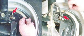
Actually, the work itself comes down to remaking the distributor, which will no longer have a high-voltage part - an electronic switch will generate high-voltage pulses for it . The photos below show the location of two sensors at once.
The sensors are attached to the base and the contact plate has curved edges
Pay attention to the shape of the contact plate:
- It has curved ends - the sensors are located vertically;
- Flat – the sensors are mounted horizontally.
Flat plate option
Flat plate option
Both options are working, it all depends on the design of the distributor. In the future, you only have to adjust the ignition. The instructions are simple - you must remember that sparking begins when the edge of the plate is in the center of the Hall sensor.
The order is as follows:
- Rotate the crankshaft until the piston in the first cylinder reaches TDC;
- Rotate the distributor body until the contact plate is in the sensor slot;
- Carefully tighten all mounting screws to eliminate any play.
- Start the engine.
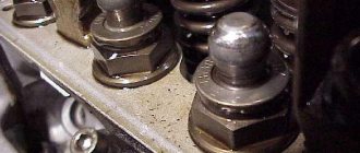
Coil device
Underwater ignition on a jeep
The UAZ 469 ignition coil has a complex design:
- screw-in terminal with high voltage;
- voltage output;
- lid;
- contact spring;
- low voltage clamp;
- gasket for sealing;
- fastening bracket;
- magnetic circuits;
- contact plate;
- primary and secondary winding;
- insulation gaskets;
- frame;
- insulator;
- iron core;
- insulating mass;
- additional resistor and its insulator;
- screw and plate for fastening the resistor.
The distributor performs the function of distributing and interrupting the ignition of the UAZ 469. It has vacuum and centrifugal regulators. The centrifugal changes the ignition angle of the UAZ depending on the frequency with which the crankshaft or camshaft rotates.
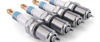
BSZ spark plugs are a very important element. With their help, the working mixture in the combustion chamber in the cylinders ignites and gives a good spark so that the car starts quickly. Most often they use A12BS spark plugs, which cannot be disassembled, so in case of a malfunction you need to have new ones in stock that can be quickly and easily replaced.
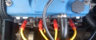
Wires for high voltage are made from PVL-1 wire. They connect the coil to the distributor, and the distributor to the spark plugs. The spark plugs are attached to the central electrode using special tips with resistors.
How to set the ignition
In order to correctly adjust and set the ignition on a UAZ, you must follow the sequence of actions that are given in the user's repair manual.
Before you begin adjusting the ignition system, you must place the vehicle on an inspection pit or a special platform for repair work and apply the hand brake. The wheel mechanisms of the vehicle must be secured with a stopper or stop. The power unit must be turned off.
Checking the Hall sensor and switch
- Turning on the ignition, remove the connector from the Hall sensor and measure the voltage between the outer contacts, there should be 12 volts, this is the power supply for the sensor. If there is power, go to the next step by plugging the connector back in, if not, change the switch, it’s dead.
- We set the tester to measure voltage (a tester with an arrow is better, it will deviate jerkily, digital testers sometimes “slow down”) and connect it, without disconnecting the switch and piercing the insulation with the ends of the probes, to contacts 6 and 3 of the switch. We turn with the starter. The tester should show pulses from 0.4 volts to no less than 9 volts. There are impulses - we change the switch. There are no pulses - we change the Hall sensor.
If someone’s octane corrector plate, which secures the distributor, has burst, then to repair it, you need to cut an M6 thread and rubber rings for sealing.
How to connect the ignition switch
Replacing the ignition switch involves dismantling the old one and installing a new mechanism with its subsequent connection. To remove the old lock you will need a Phillips and flathead screwdriver.
The procedure for dismantling the old vehicle ignition system lock:
- Remove the fasteners from the lower trim panel of the steering column.
- Insert the key into the lock and set it to the zero position, at which the steering mechanism will be locked.
- Remove the steering column.
- Unscrew the ignition switch mounting bolts.
- Insert a flat-head screwdriver into the small technological hole and press the latch that holds the lock.
- Push the lock out of its seat.
- Disconnect all system wires.
- Install a new lock, connect the wires and reassemble the mechanism, performing all the steps in reverse order.
All wires are connected in a clockwise direction.
To terminal number 50 you need to connect a red wire, which is responsible for the stable operation of the starter device.
To terminal number 15 you must connect a blue wire with a black stripe, which is responsible for heating the vehicle interior.
A pink wire is connected to pin number 30, and a brown wire is connected to 30/1.
The black wire must be connected to the INT connector, which is responsible for the operation of the side lights and headlights.
After all the wires are connected, you need to connect the battery terminal. A black wire should be connected to the top of the terminal. Then you need to start the engine and check the serviceability and functionality of the entire ignition system. First, it is recommended to check the operation of electrical devices, and then the serviceability of the starter mechanism.
If all wires are connected correctly, then when the ignition system key is in the zero position, all elements of electrical equipment will be disconnected from power. When the key is turned to the first position, the system is activated, which controls the internal combustion engine, generator set, headlights and brake lights, as well as washers and windshield wipers. When the key is moved to the second position, the starter is activated, the anti-theft system rod extends and retracts when the key position is changed.
If this does not happen, it means the wires are connected incorrectly. It is necessary to disassemble the mechanism and repeat the connection procedure.
A guide to replacing a distributor with an oil pump drive
Before installing a new distributor with a drive, you need to weigh your strengths, since it is not recommended to make mistakes when performing work.
So, how to replace and install the distributor:
- Turn off the ignition and remove the distributor cover; the tips and high-voltage cables are connected to it.
- Then you need to disconnect the wire connected to the switch from the distribution mechanism. You also need to disconnect the pipe connected to the vacuum regulator.
- Taking a 13mm wrench, unscrew the two nuts securing the device and remove the mechanism along with the oil pump drive from the power unit.
- After completing these steps, you will be able to see the gasket located under the drive. If as a result of these actions the position of the crankshaft has not changed, then simply install a new mechanism, making sure that the slider is located opposite the mark. All actions are performed in reverse order. When the installation is completed, the advance angle is adjusted.
- If, as a result, the location of the shaft has changed, then before installation it is necessary to move the piston of cylinder 1 to top dead center. You need to ensure that the marks on the pulley align with the pointer on the motor itself.
Generator wiring diagram
Elements of the G-250E1 alternator circuit, used on early machines:
- Brush.
- Contact ring.
- Excitation winding.
- Diode rectifier bridge.
- Heat sink plate.
- Stator windings.
Generator G250 with a power of 350 W
Generators with improved parameters installed on later UAZ 3151 vehicles are connected in a similar way.
Electrical diagram of the UAZ 469 old and new model with description
The composition of the electrical wiring components of the early UAZ:
- A front light used as a parking signal and direction indicator.
- Headlight.
- Connecting strip for connecting lighting devices.
- Klaxon.
- Coil.
- Additional resistance in the tips of the spark plugs, reducing the level of interference during operation.
- Spark plugs.
- Generator.
- A sensor used to turn on the warning lamp for pressure drop in the lubrication system.
- A device for measuring oil pressure in operating mode.
- Coolant temperature meter in the engine jacket.
- Sensor for turning on the overheating warning lamp, installed in the radiator.
- Battery.
- Engine compartment illumination lamp.
- Ignition pulse chopper and distributor.
- Connecting strip.
- Klaxon signal button.
- Relay for turning on the starter.
- Starter.
- Battery switch (disconnecting ground from the body).
- Regulator of the voltage level of the generated current.
- Motor for driving windshield wipers.
- Windshield wiper switch.
- Relay interrupter for direction indicators.
- Fuse box.
- Two plug sockets for supplying power to additional equipment.
- Headlight mode switch (foot switch).
- Brake signal limit switch.
- Lighting control button in the car interior.
- Lamp for illuminating the cabin interior.
- Thermal fuse (reusable).
- Additional lighting located in the rear of the body.
- Indicator lamp for excessive increase in fluid temperature in the radiator.
- Warning signal for low oil pressure.
- A control indicator displaying the operation of the direction indicators.
- Set of instruments.
- Scale illumination lamp (separate for each dial indicator).
- Speedometer.
- Central manual switch for external lighting.
- Egnition lock.
- Indicator for turning on headlights in high beam mode.
- On-board network ammeter.
- Oil system pressure gauge.
- Fluid temperature gauge in the engine block.
- Fuel level meter (works only on one of the selected fuel tanks).
- Gasoline quantity sensor switch (selects left or right tank).
- Radio receiver and speaker (optional, rarely installed from the factory).
- Steering column switch for direction indicators.
- Electric motor for the impeller of the interior heating system.
- Glow plug installed in the preheater boiler.
- A control spiral, which was used to determine the degree of glow of the candle.
- Fuel level sensor (individual for each tank).
- Rear combination lamps, which included lamps for parking lights, brake lights and turn indicators (common lamp).
- Glow plug switch.
- Switch for operating modes of the additional auxiliary heater engine.
- Separate heater motor switch.
- Plug block designed to provide current to towed devices.
On the left side of the rear light there is a transparent insert for illuminating the registration plate with a side lamp.
This diagram does not include elements that were included with some machines:
- additional rotating searchlight;
- the lamp switch in this headlight.
Composition of UAZ electrical wiring components after modernization:
- Front combination lamp with lens for position signal and direction indicator.
- Headlight.
- Fog lights are not found on all cars.
- Sound warning signal.
- Generator.
- Underhood lighting.
- Sensor for measuring the coolant temperature in the cooling jacket.
- Engine overheat sensor (installed in the tide on the radiator).
- Sensor for emergency reduction of fluid level in the brake hydraulics.
- Oil pressure indicator sensor.
- A separate element responsible for turning on the emergency pressure warning lamp in the lubrication system.
- Valve microswitch on the carburetor (forced idle system).
- Candles.
- Sensor-distributor of the ignition system.
- Electric washer pump drive motor.
- Idle speed economizer valve.
- Electromagnetic shut-off element on the carburetor.
- Coil.
- Lead-acid battery.
- Manual negative battery breaker.
- Starter.
- Additional resistor.
- Side repeater for direction indicator.
- Fog light control button on the front of the car.
- Cigarette lighter.
- Separate fuse for the cigarette lighter circuit.
- Vibrator (used as an emergency ignition system when the main one breaks down).
- Transistor switch.
- Economizer valve control controller.
- Electric motor to drive the cleaners.
- Starter start relay.
- Fuse block.
- Limit switch on the brake pedal (to turn on the brake lights).
- Steering column lever for controlling the direction indicators.
- Push-button toggle switch for external alarm.
- Turn signal relay.
- Plug connector.
- Interior lighting switch.
- Interior lighting lantern.
- Switch for operating modes of the windshield wiper and control of the supply of liquid to the windshield.
- Electric fan motor of the ventilation and heating system.
- Heater control switch.
- An additional resistor included in the fan motor circuit.
- Heater safety element.
- Egnition lock.
- Thermal fuse.
- Central external light control device.
- Foot switch for switching the operating mode of the headlights.
- Voltmeter.
- Engine lubrication system pressure gauge.
- Emergency pressure control indicator.
- Coolant temperature indicator device.
- Warning lamp for power plant overheating.
- Fuel level meter in tanks (switchable).
- Indicator of operation of direction indicators.
- Warning lamp for low fluid level in the hydraulic brake reservoir.
- Parking brake indicator.
- Sound signal control key.
- Signal lamp for active headlight high beam mode.
- Speedometer.
- Fog light switch (on the rear of the car).
- Limit microswitch under the parking brake lever.
- Reversing lamp limit switch.
- Gasoline level measuring sensor in the right tank.
- Switch for liquid level meter in containers.
- Sensor for determining the amount of gasoline in the left tank.
- Rear combination lamp.
- Rear registration plate light.
- Separate reverse indicator light.
- Plug block for connecting the trailer wiring harness.
- Fog light on the rear of the car.
Engine tuning options
Since the UMZ 417 carburetor engine has a heavy piston system, tuning is carried out according to the following scheme:
- boring of exhaust seats up to 39 mm and use of valves from 412 internal combustion engines;
- installation of a 51 mm exhaust pipe;
- Replacing the stock camshaft with a city camshaft to increase torque at low speeds.
Thus, the UMZ 417 motor was copied from the 402 power drive of the Zavolzhsky Motor Plant with minor changes. Even with existing shortcomings, the internal combustion engine serves regularly in UAZ all-wheel drive buses, trucks and SUVs, that is, in very difficult operating conditions.
Common faults
Failures associated with the UAZ 469 electrical circuit:
- battery discharge;
- wire breaks due to mechanical stress or corrosion;
- voltage drop in sections of circuits due to oxidation of contact connections;
- lack of charging due to wear of the brushes on the generator or insufficient tension of the belt drive;
- failure of part of the electrical circuit due to a blown fuse;
- burnout of one or more lighting lamps;
- Problems with the starter solenoid relay.
Specifications
Detailed review of the Sherkhan Logicar 4 car alarm: characteristics and differences, installation, configuration and operation instructions.
The ZMZ 409 Euro 3 engine has increased technical characteristics compared to its older brother. Thus, the power unit, due to the fact that it was designed on the basis of the 406, received high technical characteristics and endurance. Let's consider the main technical characteristics of the motor:
In addition to the Euro 3 standard, there are a number of modifications that are worth considering:
- ZMZ 409.10 is the main motor, meets the Euro-2 environmental standard. Power 143 hp
- ZMZ 40904.10 - analogue of 409.10 with a new CPG, new gaskets, DBP, complies with the Euro-3 environmental standard. Power 128 hp Installed on Patriot, Hunter, Pickup, Cargo.
- ZMZ 40905.10 - analogue of 40904.10, compliance with the Euro-4 environmental standard. Power 128 hp Installed on Patriot, Hunter, Pickup, Cargo.
- ZMZ 4091.10 - derated low-end version of ZMZ 40904.10, another receiver, camshafts (lift 8, phase 240), firmware, complies with Euro-3 environmental standard. Used on UAZ loaves. Power 112 hp
- ZMZ 40911.10 is an analogue of ZMZ 4091.10, DBP, meets the Euro-4 environmental standard. Used on UAZ loaves. Power 112 hp
- ZMZ 4092.10 is a non-serial motor. Power 160 hp Used on the Volga.
Prevention measures
Basic measures to prevent electrical system malfunctions:
- Regularly check the condition of the wire tips installed on the battery terminals. Clean parts from oxides and dirt.
- Wipe the battery case from dust. If a serviceable battery is used, it is necessary to clean the ventilation ducts and bring the electrolyte density to normal. Periodically recharge the device from the charger.
- During long periods of inactivity, disconnect the battery using the standard disconnect switch.
- The wiring harness should not bend or rub against sharp edges of the body panels. If damage to the insulation is detected, restore the protection with insulating tape or replace the wiring section. Protect the bend points with special sleeves.
- If a fuse blows, determine the cause of the failure. It is prohibited to carry out repairs by installing reinforced elements designed for increased current.
- Monitor the condition of the starter by periodically cleaning the rubbing elements from dirt and lubricating them with Litol-24. Check the axial clearance of the rotor, which should be within 1 mm, and the tightness of the bolts securing the unit to the engine crankcase. Electrical contacts must be cleaned of carbon deposits using a file.
- Clean the distributor slider from dust and oil using a rag and clean gasoline. At the same time, lubricate the rotor bushing (a few drops are applied under the removed felt). High-voltage wires must be installed tightly in the seats. If moisture gets on the elements, wipe them with a clean and dry cloth.
- Do not overuse the emergency vibrator, which has a service life of about 30 hours. When switching on the backup ignition, deactivate the carburetor economizer.
- Check the fastening of devices in the instrument cluster, replacing burnt parts.