1.
Unscrew the seven screws securing the decorative steering shaft casings and.
4.
Remove the instrument cluster from the instrument panel (
see subsection 8.6.1. ).
5.
Disconnect the ignition switch wire block from the ignition switch relay and.
7.
Unscrew the two bolts securing the ignition switch and.
9.
Remove the ignition switch and its mounting bracket from the steering shaft. Install the ignition switch in the reverse order of removal. Before installing the steering shaft housings, check the operation of the ignition switch and light alarm when the ignition is on.
Source
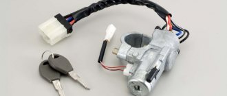
Ignition switch VAZ 11113 oka
Unfortunately, the ignition switch of the VAZ 1111 “Oka” model cannot be called the most reliable part of this, in general, not bad, and most importantly, inexpensive car. The presence of a design flaw, expressed in the fragility of the plastic guide cams of the lock, has led to the fact that Oka owners sooner or later have to face the problem of checking this switch, with the prospect of its removal and subsequent repair or replacement.
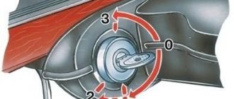
According to its operating principle, this switch is equipped with a special anti-theft mechanism that jams the steering column when the key is removed. The anti-theft device is disabled when the key is turned from position “III” to position “0”, while slightly turning the steering wheel in both directions.
When the key is moved from position “I” to position “II” in case of restarting the engine, the starter power circuit is blocked and in such a situation, starting the engine will not be possible until the key is returned to its original position “0” (only after this position “II” will ensure that the engine turns on). More detailed information about the purpose of the wires and their color markings is provided by the ignition switch connection diagram.
As for the most common failures of the ignition switch, they are usually manifested by the lack of response of electrical equipment and devices to the key inserted into the lock, as well as the inoperative state of the anti-theft device.
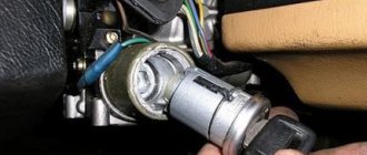
If you need to remove the ignition switch on an Oka car, the first thing you need to do is disconnect the negative terminal from the battery.
Next, unscrew the seven mounting screws and remove the upper and lower decorative steering column covers.
After this, it becomes possible to remove the instrument assembly and disconnect the ignition switch control wire block.
The ignition switch itself is removed together with its mounting bracket by unscrewing two screws. Among other things, do not forget to disconnect the ground wire of the switch from the general wiring harness.
Reinstalling the sensor has no special features and is carried out in the reverse order.
When checking the lock for functionality, you can use a conventional multivoltmeter; in this case, it is enough to measure the closure of the switch contacts at different key positions using the combinations below:
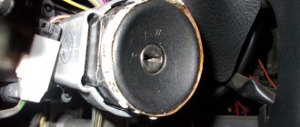
During my next trip to the city on business, a breakdown occurred while the car was moving. The car is Oka 11113. While driving around a turn, the car stalled, when I tried to start it again, I realized that the key did not turn in the ignition to the position where the starter was activated, and the movement of the key itself became somehow tight. After some thought, I called my brother by phone and drove his car, went to the auto store, bought a new ignition switch (350 rubles).
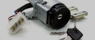
For all this action we will need: a Phillips screwdriver, a 10mm wrench, a hammer, a chisel, the ignition switch itself and of course two “tricky” bolts.
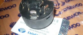
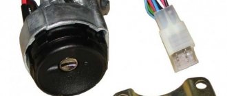
You can see what the ignition switch and bolts look like in the photo, attached:
So, it’s clear why we need a screwdriver, but why do we need a hammer and chisel? They play a key role in unscrewing those very ingenious bolts that hold the ignition switch. Of course, you can drill them out. But it seems easier to me to just gently tap, placing the chisel towards the head of the bolt in the direction of unscrewing, slightly loosen the grip and then they can be easily unscrewed by hand. Did you unscrew it? Great. I did it, a little awkward, but completely doable. After that, we install a new lock, just like the broken one, and fasten it with new bolts, use a 10 key.
At the end of twisting, they break off on their own and we get what we had at the beginning, when we picked up the chisel and hammer. Screw the casing into place.
Okavodov Club of Novosibirsk
Current time: 02 Aug 2022, 13:29Time zone: UTC + 7 hours
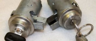
Fuse diagram for VAZ-1111 and 11113
The fuse block is located at the bottom of the instrument panel on the driver's side. The unit is protected on top by a quick-release plastic cover with a spring lock. The machine uses obsolete cylindrical type fuses. A list of inserts is printed on the outside of the lid.
Fuse markings on the cover
If a fog light is installed on a VAZ-1111 or 11113, it is protected by a separate insert (nominal 8A) located on the wiring harness next to the control button.
List of fuses with a description of the protected circuits on cars with a carburetor engine:
| Number on the diagram | Denomination, A | Protected elements |
| 1 | 16 |
|
| 2 | 8 |
|
| 3 | 8 | Left side high beam and indicator lamp in the instrument cluster. |
| 4 | 8 | Starboard main beam. |
| 5 | 8 | Low beam on the left side of the car. |
| 6 | 8 | Likewise on the right side |
| 7 | 8 | Side lights on the left side (front and rear), registration plate illumination and indicator for turning on the “dimensions” (in the instrument cluster) |
| 8 | 8 | Dimensions of the starboard side, lighting system for the cigarette lighter socket and instrument cluster |
| 9 | 16 | Operation of turn signal indicators in hazard warning mode, rear window heating filaments together with the control relay |
| 10 | 16 |
|
egnition lock
| Page 1 of 1 | [Messages: 5] |
| print version | Prev. topic | Track. subject |
| Author | Message |
| alexs |
Registered:
07 Jul 2013, 17:32
Messages:
1
Car:
VAZ-1111
Name:
Vasya
| oka275 |
Registered:
April 10, 2007, 22:36
Messages:
10745
From:
Novosibirsk, Dzerzhinsky
Car:
VAZ-21043
Name:
Alexey
| Nick S. |
Registered:
12 May 2014, 08:37
Messages:
60
From:
Akademgorodok
Car:
VAZ 11113
Name:
Nikolay
Okushka threw up a surprise, which, of course, could have been expected, but not in this form.
I already had the problem that the starter with the key stopped starting and I installed a button. I thought that the problem was in the contact group, but it turned out to be. Yesterday the lock jammed tightly, fortunately in the completely off position, that is, you can insert the key, but it refused to turn tightly. The steering wheel is naturally jammed.
I had to tinker with removing the lock, fortunately everything was close to the work and a chisel with a hammer was not a problem. The contact group turned with a finger, the starter pressed the button and off we went. I arrived at the store on Pasechnaya, through a terrible traffic jam on Kutateladze. And it's closed there. Of course, it would have been possible to go to Volga Motors, but I was still too lazy to stand in traffic jams, so I moved to the den.
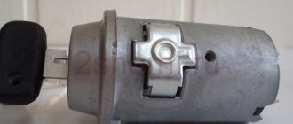
In the morning again to Pasechnaya, there was only an old type lock, I took it, remembering that in any case it was possible to switch somehow, I read about it. When I arrived at work, I compared it and realized that I had a new type, but my contact group easily fit on the new piece of hardware. I decided not to bother with tricky screws, because if someone decides to steal it, everything is done in five minutes and this stupidity still won’t help. By the way, replacing the old contact group with a new piece of hardware will not work, since the casings are different both in the design of the installation (latches and protrusions on the pins) and in the design of the cover (there must be additional cavities for the fifth and sixth contacts).
Just for memory, the old style contact group has six tails, the new one has four.
The castle rose heavily.
Firstly, according to Feng Shui, the ground contact with the relay should be located next to the choke handle, but it simply comes out of the harness. Naturally, he disguised himself and the search for him took some time. Second, the radius of the iron clamp was very different from the radius of the steering column. I had to tighten it with a welding clamp so that the screws would go in correctly and not at an angle. Also a fun and unexpected twist. Everything else worked out without problems.
It’s a pity I couldn’t take any photos – I had nothing.
Source
Ignition of the Eye
When designing the small car VAZ Oka 1111 and 11113, many components and mechanisms were “borrowed” from other VAZ models, which made it possible to reduce the cost of car production and speed up the start of production. But the designers had to significantly rework some components in order to adapt them to the features of the Oka engine. One of these components is the ignition system.
When creating the ignition system, the designers used modern developments of those years. The VAZ Oka received a non-contact ignition system. At the same time, the features of the power plant made it possible to somewhat simplify the system and reduce the number of components, which had a positive impact on the reliability of this component of the power plant.
Fuse box diagnostics (video)
VAZ-1111 especially small class passenger cars are equipped with 12-volt electrics with a negative terminal connected to the car body. The cars were equipped with carburetor and injection power units, which had little effect on the location and purpose of the circuits. The VAZ-1111 electrical circuit, which is basic for all versions of the Oka, can be used when repairing a car of any year of assembly.
What is included in the Oka electrical circuit?
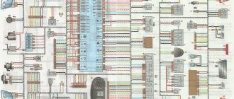
Electrical diagram of VAZ-1111 with symbols
Electrical diagram of VAZ-11113 with symbols
Contactless ignition diagram indicating the main elements and connecting wires
Fuse diagram for VAZ-1111 and 11113
Common electrical faults
Design
The ignition system of the VAZ Oka consists of only seven main elements:
All elements are connected to each other by wiring.
Using the ignition switch, the driver controls the power supply to the system from a source - the battery, while the voltage passes through the auxiliary relay and fuses. The lock has three positions - “0”, in which all electrical consumers are turned off, “1” - voltage is supplied to the ignition system and a number of other devices, and “2” - current is supplied to the starter. This switching sequence ensures that the ignition system is activated at the moment the engine starts.
Spark torque sensor
The spark timing sensor is one of the main ignition components, since it sets pulses that are subsequently converted into a spark discharge between the spark plug contacts. This sensor is driven by the camshaft, which allows you to accurately set the timing of the spark in the cylinders.
The main working elements of the unit are the Hall sensor and a special screen with slots mounted on the drive shaft interacting with the camshaft. The interaction of these elements leads to the emergence of control impulses.
The sensor not only sets pulses, it also “adjusts” to the operating conditions of the motor, adjusting the advance angle depending on the operating conditions of the motor (speed, load).
The adjustment is carried out by two regulators - vacuum and centrifugal, included in the design of the spark generation moment sensor.
Until 1989, Oka used a sensor of type 55.3706, and after that it was replaced by model 5520.3706.
Switch
The switch acts as a circuit breaker for the primary winding of the coil, using control pulses coming from the spark sensor. Circuit interruption in the switch is performed by the output transistor. The switch is completely electronic, without any moving elements, so the ignition system is contactless.
Several types of switches were installed on the VAZ-1111 and 11113 - 36.3734, 3620.3734, as well as HIM-52. The switch is installed in the engine compartment near the engine panel. It is secured with two bolts, so replacing the switch is quite simple.
Coil
Oka received a two-terminal ignition coil, which made it possible to remove the distributor from the design.
It is noteworthy that the high voltage in this coil is supplied simultaneously to both spark plugs. Moreover, due to the offset strokes in the engine cylinders, only one spark discharge is working, the spark on the second spark plug is the so-called “idle”.
The standard coil on the Oka is type 29.3705, but it has an analogue that is suitable for use on a small car - 3012.3705.
Wires, spark plugs
All wiring consists of low and high voltage wires. The first ones are used to connect all the components up to the coil. These are ordinary wires of small cross-section, which is quite sufficient, since the voltage in the circuit up to the coil is low.
High voltage wires are used to connect the coil terminals to the spark plugs. For ease of connection, lugs are installed at the ends of these wires.
Recommended for use on Oka are spark plugs of type A17DVR - with an extended thread and an interference suppression resistor, as well as their analogues.
Electrical diagram of VAZ-1111 with symbols
List of elements indicated in the diagram:
- 1 — side turn signal repeater located on the front fender;
- 2 — front direction indicator;
- 3 — head lighting device;
- 4 - electric motor used to drive the radiator cooling impeller;
- 5 — warning sound signal (horn);
- 6 - temperature sensor, which ensures that the cooling system impeller is turned on;
- 7 — motor for driving the front window washer pump;
- 8 — distribution sensor of the ignition system;
- 9 — lead-acid battery;
- 10 - electric motor for starting the engine;
- 11 — ignition system controller;
- 12 — spark plugs installed in the cylinder head;
- 13 — ignition system coil;
- 14 — alternating current generator;
- 15 — liquid temperature indicator in the cooling jacket;
- 16 - control sensor that determines emergency oil pressure in the engine;
- 17 — connector for installing a portable lamp;
- 18 — windshield wiper operation controller;
- 19 — indicator sensor of the fluid level in the hydraulic brake drive system;
- 20 — brake pedal position limit switch;
- 21 — motor for driving the trapezium wipers on the front window;
- 22 - electromagnet located in the carburetor valve;
- 23 — limit switch responsible for the operation of the reverse gear signals;
- 24 — starter controller;
- 25 — headlight control relay (low beam);
- 26 - similar unit for high beam;
- 27 — controller of direction indicators and emergency lights;
- 28 — cigarette lighter socket;
- 29 — speed switch for the heating system motor;
- 30 - additional resistor that determines the rotation speed of the heater fan impeller;
- 31 — external lighting operating mode switch;
- 32 - fuse block;
- 33 — additional protective element for fog lamps;
- 34 — rear window heating control controller;
- 35 - start relay, necessary for the operation of the cooling system fan;
- 36 — control relay for the control indicator of the position of the parking brake lever;
- 37 — control of the rear window cleaning system (together with the washer);
- 38 — glass heating operating mode switch;
- 39 — rear fog light button;
- 40 — indicator of the open starting valve in the carburetor;
- 41 — alarm control button;
- 42 — ignition switch;
- 43 — distribution relay of the ignition system;
- 44 — heating fan impeller motor;
- 45 — indicator of the amount of gasoline in the tank;
- 46 — interior lighting switch located on the central pillar;
- 47 — instrument cluster;
- 48 — front wiper control;
- 49 — turning on the windshield washer;
- 50 — horn control button;
- 51 — lever for changing the operating modes of the head lighting;
- 52 — direction indicator control lever;
- 53 — limit switch, responsible for indicating the position of the parking brake lever;
- 54 — interior lighting lamp;
- 55 — limit switch located behind the carburetor choke control button;
- 56 — motor for driving the glass washer pump on the rear door;
- 57 — stern canopy;
- 58 - fog signal, located on the rear of the car;
- 59 — registration plate illumination system;
- 60 — tailgate glass heating threads;
- 61 — stern wiper blade drive motor.
The specified colors of connecting wires correspond to the factory documentation. During repairs, many owners replace sections of the harnesses with cables with insulation of a random color. Because of this, some vehicles have difficulty identifying the wiring.
How it all works
The principle of operation of the ignition system is as follows: after turning the key to position “1” el. Energy from the battery is supplied to the ignition system components through the lock, fuses and auxiliary relay. In this case, high voltage pulses are not generated, since the spark torque sensor is not yet operational.
After activating the starter, the timing drive begins to rotate the camshaft, and accordingly the sensor shaft - the Hall sensor begins to interact with the screen, due to which control pulses are created.
Arriving at the commutator, these pulses interrupt the power supply circuit of the coil winding. When the power circuit is broken, a high voltage pulse is induced in the coil, which is transmitted through high-voltage wires to the spark plug, which leads to the formation of a spark between its electrodes.
Setting the advance angle
Setting the ignition timing is the only operation that is performed in the ignition system.
A strobe light is used to set the angle correctly. The technology for performing the work is not complicated. The algorithm of actions is as follows:
- We connect the strobe to the power source and the tip of the spark plug of the 1st cylinder (according to the instructions for the device);
- Remove the plug from the inspection window on the clutch housing;
- We start the engine (it should be idling);
- We direct the beam of light from the strobe into the viewing window;
- We determine the position of the marks (with the angle correctly set, the mark on the flywheel at the moment the strobe light beam flashes should be located between the central and rear marks on the crankcase);
- If the marks are not positioned correctly, make adjustments. To do this, loosen the bolts securing the spark moment sensor and rotating it around its axis until the marks match;
After adjustment, tighten the sensor fasteners, turn off the engine, disconnect the strobe light and replace the plug.
Malfunctions
The simplified design of the ignition system and the absence of moving components ensures high reliability and ease of maintenance.
There are not so many malfunctions in the Oka ignition system:
Since the ignition system is directly involved in the operation of the engine, any malfunction in it immediately affects the performance of the engine - interruptions occur, the unit does not develop power, popping noises appear, or the unit simply does not start.
Diagnosis of a malfunction is carried out by visual inspection of the wiring and its connections, as well as by sequentially replacing all components with known good ones. A check using measuring instruments allows you to more accurately determine the faulty element.
The search for the problematic element is carried out from the candles. That is, first the presence of a spark is checked on them, then the high-voltage wires are inspected, and then the performance of the coil, switch, and Hall sensor is diagnosed.
The components of the ignition system are non-repairable, so if they break down they must be replaced.
Replacing the ignition switch
Hello everyone! Today, after a long time, I wanted to write to Oka’s BZ. It so happened that we spent the winter in the garage. In December we stopped at the garage, and in January we bought a Lada Kalina car, since Oka didn’t always want to go somewhere in the cold, starting it on the street was problematic, and I was a little tired of going to the garage all the time. And the family began to insist on buying a car, so to speak, more comfortable, for some long trips. Actually, after purchasing Kalina, the need for further operation of the Oka disappeared and I only drove Kalina. In January, an attempt was made to start the Oka (a friend needed to change the heater tap on the car, it’s more convenient to do this in the garage), but after a couple of attempts to turn over the engine, the ignition switch was broken, she was probably offended by me, or maybe she just liked it in the garage so she decided to stay in the warm garage. I didn’t bother with repairs, and it stayed like that for 4 months until today.
Replacing the ignition switch is not a complicated procedure, but it is terribly inconvenient to change it; your arms and back will get tired)) The only tools you need are: a Phillips screwdriver, a 10mm wrench, a hammer, a chisel, and the ignition switch itself and two bolts (the kit includes 2 bolts with with breakaway heads, but I didn’t use them, I used the old ones, fortunately, apparently this part had already been replaced on the car, probably my grandfather changed it at one time and did not tighten it with breakaway ones, I picked up similar bolts with a 10-mm head and tightened them in. But I was afraid, I thought I would have to I had to drill them out, but everything worked out fine.
I removed the ignition switch to service it (the key started to stick when the ignition was turned off). And I broke off one of the riveted terminals. There is nothing to do, I still wanted to install a regular switch instead of a lock. And away we go. It turned out that the harness of the removed lock can easily be adapted to work without a lock. We just add a second relay.
I did not remove the lock. Let it be for furniture. And I hid the button. Kind of a secret...
If necessary, I'll post a diagram. But it doesn’t seem to be complicated. The only thing that needs to be added is an audible alarm so that you don’t leave the car without leaving the ignition on. However, if you use the signal correctly, this will not happen. But I was unlucky: today I found out that my alarm does not block the ignition. So the apocalypse will continue.
By the way, can anyone tell me if there is such a cunning relay in nature, in which both positions are stable? Those. so that after each switching the relay does NOT require power and it retains its accepted position. Based on the trigger principle. Of course it’s interesting at 12V. Such a thing would be very useful when activating the signaling. And not only…
And a small addition for those who want to repeat the alteration. It is better to screw the new relay to the steering column with self-tapping screws. There is already a standard ignition relay there and I screwed it on a long time ago. We add a second one instead of the ignition switch. And from it we pull four wires to the steering wheel. Everything is corrugated. We bite off the thick wires from the ignition switch and re-route them to the new relay. Corrugation is a must. If these wires are shortened, the car is destroyed and a fire is guaranteed. Therefore, we lay them without pinching, no sharp edges nearby, and protect them with corrugation. It is very convenient to use the standard connector from the ignition switch wire. This way you can assemble everything at home, and then just put it in the car. I got it right without errors and everything worked after the first connection.
Electrical diagram of SeAZ-11116
On SeAZ-11116 cars with a Europanel and a Chinese 3-cylinder engine, the electrics have undergone changes. The cars use an electronic instrument cluster, which has led to the emergence of a number of new sensors. The fuel supply system was changed, into which a fuel pump with a control relay was introduced. Big innovations appeared in the engine compartment, where a fuel injection and ignition control system began to be installed. At the same time, the main part of the wiring, the fuse and relay box was carried over unchanged from the old carburetor version.
The diagram shows the following electrical equipment components:
| Number on the diagram | Element designation |
| 1/1 | High beam thread |
| 1/2 | Low beam thread |
| 2 | Front turn signal lamp |
| 1/4 | Side light |
| 3 | Side repeater |
| 5 | Generator and built-in relay regulator |
| 9 | Hall Sensor |
| 10 | Ignition coil |
| 12 | Starter |
| 13 | Spark plug |
| 14 | Klaxon |
| 17 | Coolant temperature sensor |
| 18 | Sensor for determining emergency oil pressure |
| 23 | Battery |
| 25 | Reversing signal switch |
| 26 | Device for turning on and off brake signals |
| 30 | Turn signal control relay |
| 31 | Parking Brake Warning Indicator Controller |
| 32 | Block for changing the operating mode of the windshield wiper |
| 33 | Additional heater motor resistor |
| 35 | Windshield wiper drive motor (front) |
| 37 | Heater fan motor |
| 38 | Radiator impeller drive |
| 39 | Cooling system motor control relay |
| 42/1 | Steering column turn signal switch |
| 42/2 | A similar element for headlight modes |
| 42/3 | Steering column for controlling the windshield wiper and washer |
| 42/4 | Steering wheel button for horn |
| 44 | Egnition lock |
| 46 | External lighting control (dimensions) |
| 48 | Alarm management |
| 49 | Switching heater fan speeds |
| 52 | Instrument cluster |
| 63 | Speed sensor |
| 74/1 | Cigarette lighter |
| 74/2 | Cigarette lighter socket illumination system |
| 75 | Fluid volume measuring sensor in the brake drive |
| 76 | Parking brake limit switch |
| 77 | Diagnostic connector |
| 81 | Portable lamp socket |
| 83 | Washer pump drive |
| 87 | Limit switch for interior lighting system (on the door) |
| 89 | Interior lighting |
| 93 | Sensor measuring fuel level (with backup indicator) |
| 98/1 | Rear light size |
| 98/2 | Turn signal located in the stern lights |
| 98/3 | Brake lamp |
| 98/4 | Reverse gear indicator |
| 99 | License plate light |
| 104 | Radiator Fan Thermal Switch |
| 108 | Rear fog light |
| 112 | Tail wiper motor |
| 113 | Rear window washer motor |
| 115 | Rear window heating filaments |
| 121 | Heated glass controller |
| 125 | Additional relay |
| 126 | High beam controller |
| 127 | Similar device for low beam |
| 129 | Starter controller |
| 133 | Heated rear window switch |
| 136 | Tail fog control |
| 137 | Rear window wipe control |
| 138 | Turning on the tailgate glass washer |
| 158 | Fuel injectors |
| 159 | Watch |
| 168 | Rear Fog Lamp Controller |
| 169 | Third brake light |
| 170 | Fuel pump controller |
| 171 | Fuel pump |
| 172 | Idle speed control system |
| 173 | Throttle valve angle sensor |
| 174 | Knock sensor |
| 175 | Canister purge system |
| 176 | Lambda probe |
| 177 | Absolute pressure sensor |
| 178 | Main relay |
| 221 | Engine control system controller |
Replacing the ignition switch and contact group on a VAZ 2108, VAZ 2109, VAZ 21099
Welcome! The ignition switch breaks quite rarely, but it still happens. After a lock breaks, it of course needs to be replaced with a new one, but how to do this, you ask? Some people still know the answer to this question, but some do not. For those who don’t know, we have prepared this article, which will describe in detail the process of replacing the ignition switch. And at the end of this article you will find a video clip that will describe in detail the process of replacing this lock.
Note! To replace the ignition switch, you will need the following tools: First, you will need screwdrivers, and you will also need a drill, a small hammer, pliers, and you will definitely need to stock up on a chisel!
Summary:
When do you need to change the ignition switch and contact group? It must be replaced if it breaks, as well as if the key is lost, and even if the cylinder in the lock stops turning and is stuck in one place. The contact group must be replaced if it is deformed, and even if, after turning the key in the lock, the car’s engine stops starting.
Irregularities in the fuel system
The operation of the Oka fuel system is to ensure that the mixture is supplied along with air and fills all cylinders with it. An important component that is responsible for the serviceability of this system is the carburetor. How can you identify problems with the fuel system?
The main reason for these problems is severe contamination of the air filters and lack of fuel mixture. If there is no gasoline supply to the carburetor, then first of all it is recommended to check the condition of the fuel pump, pipes, and cleaning filters for damage.
How to replace the ignition switch, check the contact group and replace it on a VAZ 2108-VAZ 21099?
Replacing the ignition switch:
Removal: 1) Starting with “The battery is a rechargeable battery,” unscrew the nut that holds the “-” terminal on the battery and then remove the terminal. (How to remove the negative terminal from the battery, see the article about “Replacing the battery on a VAZ”, in the “first” paragraph)
2) Then remove the steering column cover and both steering column switches. (How to remove the casing and both switches, see the article: “Replacing under-steering switches”)
3) Next, insert if the lock allows it, then insert the ignition key into it and put it in position “0”.
Note! The key must be installed in this position only to disable the anti-theft device!
4) Now remove the four bolts that secure the ignition switch. If you have these bolts with a cut off head, then knock them down with a hammer and chisel. (Be sure to read the “Important!” paragraph)
Note! If that doesn’t work, then try drilling out all four bolts, but just do it carefully without damaging anything!
5) Once the bolts are loosened, use pliers to remove them from the hole.
6) Next, remove the bracket on the left side, and the ignition switch on the right.
7) Now disconnect the wire block from the electrical connector.
And finally, crawl under the dashboard, and there, disconnect the connector going from the ignition switch to the relay.
Installation: Installation of a new lock is carried out in the reverse order of removal.
Checking the contacts of the wire block:
1) First, remove the lock from the car using the text above.
2) Next, using an “Ohmmeter” or a “Multi-meter” with the “Ohmmeter” function enabled on it, connect its leads to the electrical connector and then look at the readings of the device.
Note! The device should clearly display “0”; otherwise, replace the contact group!
Replacing the contact group:
1) First, on the removed ignition switch, use a screwdriver to unscrew the screw that secures the ignition switch cover.
2) Then use a screwdriver to press out the two plastic latches securing the lock cover.
3) Then remove the cover.
4) And finally, remove the contact group from the ignition switch.
Note! Installation of the contact group is carried out in the reverse order!
Important! Not on all cars of the Samara family the ignition switch is attached to the steering column with four bolts; on some cars it is attached only with two bolts and on top it is secured with a hook indicated by a red arrow!
Additional video material: Below we have prepared a video related to replacing the ignition switch on cars of the Samara family.
You may also like
General scheme
The general diagram of the electrical equipment of the VAZ 11113 is presented below:
1 – turn signal repeater; 2 – front turn signal; 3 – headlight; 4 – el. fan motor with cooling; 5 – signal; 6 – fan switching sensor; 7 – el. washer pump motor; 8 – spark supply moment sensor; 9 – battery; 10 – starter; 11 – switch; 12 – candles; 13 – coil; 14 – generator; 15 – temperature sensor; 16 – oil pressure sensor; 17 – 12 V socket; 18 – windshield wiper relay; 19 – brake fluid level sensor; 20 – brake light switch; 21 – el. windshield wiper motor; 22 – el. carburetor magnetic valve; 23 – reverse light switch; 24 – starter relay; 25 – low beam relay; 26 – high beam relay; 27 – alarm relay; 28 – cigarette lighter; 29 – electric switch. stove motor; 30 – extra electric resistor stove motor; 31 — lighting switch; 32 – safety block; 33 — PTF power supply fuse; 34 – relay for turning on the rear window heater; 35 – electric switching relay. fan motor with cooling; 36 – parking brake control relay; 37 – rear window heater and washer switch; 38 – rear window heater switch; 39 – rear PTF switch; 40 – carburetor suction control; 41 – alarm switch; 42 – ignition switch; 43 – ignition relay; 44 – el. stove motor; 45 – fuel sensor; 46 – lamp switch; 47 – dashboard; 48 – windshield wiper switch; 49 – glass washer pump switch; 50 – signal switch; 51 – light switch; 52 – turn signal switch; 53 – brake light switch; 54 – interior lamp; 55 – carburetor suction control switch; 56 – el. rear window washer motor.
Design
The ignition system of the VAZ Oka consists of only seven main elements:
All elements are connected to each other by wiring.
Using the ignition switch, the driver controls the power supply to the system from a source - the battery, while the voltage passes through the auxiliary relay and fuses. The lock has three positions - “0”, in which all electrical consumers are turned off, “1” - voltage is supplied to the ignition system and a number of other devices, and “2” - current is supplied to the starter. This switching sequence ensures that the ignition system is activated at the moment the engine starts.
Spark torque sensor
The spark timing sensor is one of the main ignition components, since it sets pulses that are subsequently converted into a spark discharge between the spark plug contacts. This sensor is driven by the camshaft, which allows you to accurately set the timing of the spark in the cylinders.
Instrument cluster diagram
- Coolant temperature indicator sensor;
Fuel level indicator with reserve indicator lamp;
- Indicator lamp for brake fluid level and parking brake system;
- Oil pressure warning lamp;
- Coolant temperature gauge;
- Fuse box;
- Ignition switch;
- Parking brake warning lamp switch;
- Parking brake warning lamp relay;
- Brake fluid level sensor;
- Oil pressure warning light sensor;
- Level indicator and fuel reserve sensor.