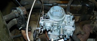
Purpose
The most important function of this device in a car is the preparation and dosage of a mixture of fuel and air at any engine operating mode. The DAAZ-2105 carburetor also performs the following functions. This is ensuring a cold start of the engine, supplying limited portions of fuel in idle mode, preparing and supplying an emulsion to the engine intake manifold at engine operating modes, dosing portions of the mixture depending on the opening angle of the throttle valves, injecting additional gasoline when accelerating the car and when accelerating, pressed until the end of the stroke.
Operation and repair of the device
The carburetor serves to form a combustible mixture by combining injected fuel and air, in order to ensure the operation of the internal combustion engine. In this case, the correct proportions must be observed to ensure normal combustion. If the proportions are not observed, an over-enriched mixture is formed due to an excess amount of fuel or lack of air, which leads to breakdowns.
The carburetor includes a system that maintains the required fuel level; a system responsible for starting and warming up a cold engine; idle system; main dosing system; acceleration pump; econostatic system. Adjusting the idle speed of the VAZ 2105 should be performed exclusively on the engine, which is warmed up in advance. The temperature value of the coolant should fluctuate around 90-95 degrees.
In addition, you need to adjust the gaps on the gas distribution mechanisms and open the air damper. Special attention should be paid to the correct setting of the ignition timing. When adjusting carburetor 2105, first of all, set the crankshaft rotation frequency to 700-800.
This process is carried out by means of a screw that regulates the composition of the mixture, after which the same screw achieves a carbon monoxide concentration of approximately 0.05.2% reduced to 20 ° C and 760 mm Hg. Art. with the screw in the above position. After this, using the first screw, you need to restore the crankshaft rotation frequency to 700-800. Using the second adjustment screw, the carbon concentration value can be restored as a percentage to 0.05.Jan.2.
Then, by sharply pressing the throttle drive pedal and then releasing it, the engine will increase the crankshaft rotation frequency, and if it decreases, the engine will stall. In this case, using the first screw, you should again increase the rotating frequency to 750-800, after which a plastic plug is installed in the hole for the second adjusting screw. After all these steps, the adjustment process 2105 is considered complete.
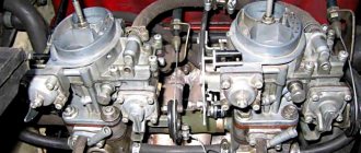
When installing a carburetor on a classic VAZ 21053, you should remember that, unlike the VAZ 2105, 21053 20 has a somewhat poor second chamber. This is explained by the fact that the first has a fairly rich adjustment. It can be made poorer by installing 102-150 jets, but then there will be a need to enrich the second chamber by installing 115-135 jets.
Considering the technical characteristics of the VAZ 2105, of course, it is necessary and more advisable to install the 2105 Ozone carburetor, but still, installing the 21053 20 carburetor is also considered acceptable. In order to increase engine power and the efficiency of the VAZ 2105 carburetor, a compressor is usually installed on the car.
The effectiveness of this method lies in the fact that when a compressor is installed, the charge of the fuel-air mixture increases. The mixture enters the cylinder due to increased air supply to the fuel system. The compressor has not only advantages, but also disadvantages, one of which is increased fuel consumption.
The compressor consists of a pulley, a drive gear, a rotor driven gear and an internal oil gear. All installation work should be carried out with the engine cool. After installation, the compressor should have minimal resistance to air movement. Typically, an installation kit is used for this, which includes all the necessary parts. A mechanical supercharger (compressor) plays an important role in the process of improving the quality of a car.
Device
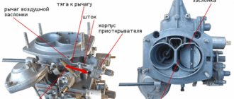
In the design of the DAAZ-2105 carburetor, three main parts can be distinguished. This is the cover, the main block, and also the housing in which the throttle valves are located.
There is a built-in starting system installed in the carburetor cover - it is semi-automatic. The lid also contains a fine fuel filter, a needle valve and a float, and an econostat tube. The top cover is secured to the middle part of the carburetor using five screws.
The main part has a more complex structure. There is a float chamber for fuel, and the main metering system is built here, consisting of air and fuel jets and diffusers - large and small. In the middle part there is also a diaphragm accelerator pump with a ball valve, channels for powering the transition system and idle channels. In the middle part there is a vacuum drive for the throttle valve of the second chamber.
At the bottom of the DAAZ-2105 carburetor there are damper axles, as well as screws for adjusting the operation. These are the screws of mixture quantity and toxicity. In addition, the lower block has a lot of channels for the operation of the idle system, transition and starting systems. The lower part of the carburetor is attached to the middle main part with screws.
Carburetor VAZ 2105 - general information
On the fifth model Zhiguli we are interested in, the main power unit is a four-stroke four-cylinder internal combustion engine with a volume of 1.45, 1.29 and 1.57 liters.
Russian Ozons (DAAZ 2105) of several modifications are used to form the combustible composition for the “five” engine.
The most commonly installed models were 2105-1107010-20 and 2105-1107010-10. Their difference lies in the size of the cross section of the two elements:
- additional pipe;
- fuel main jet located in the primary chamber.
Carburetors of these modifications have five main mechanisms:
- econostat system;
- dosing main chamber;
- system for starting a cold engine and warming it up;
- accelerator pump;
- idle system;
- system responsible for maintaining the required level of gasoline.
The VAZ 2105 carburetor jets are marked as follows:
- 2105-1107010-10. Air jet: main system - 170 for the first and second chambers, idle speed - 170 and 70, respectively. Fuel: main system - 109 and 162, idle - 50 and 60. Accelerator pump: 40 (bypass and fuel).
- 2105-1107010-20. All markings are similar to the previous model, with the exception of the fuel cell of the main system - 107 (in 2105-1107010-10 marking 109).
In general, the “five” carburetor is a rather complex device that ensures stable operation of the car engine in different modes, mixes vehicle fuel and air in a given proportion, and then supplies the resulting combination to the cylinders of the power plant. Its correct setting guarantees economical fuel consumption and stable operation of the “heart” of the car.
Operating principle
If car enthusiasts do not understand the basic principles of carburetor operation, then repairs and adjustments can present certain difficulties.
The principle of operation of the mechanism is based on the fact that the engine creates a vacuum with its pistons. That is, the fuel is drawn in by the air flow. Fuel is dosed due to the presence of jets - these are small parts with calibrated holes. They are located inside the carburetor channels and are capable of passing only a certain amount of fuel or air.
How is the carburetor float device adjusted?
Experts say that it is possible to adjust the carburetor without necessarily removing it from the vehicle. A float mechanism is responsible for ensuring the required volume of fuel in the described device, which is adjusted as follows:
- the engine is started and it idles for several minutes;
- The carburetor cover is removed and the fuel level is measured, which should be 28 millimeters.
If these same 28 mm are not observed, perform:
- bending the float tongue touching the needle valve (more precisely, its ball) to a value of 6.2 to 6.75 mm;
- After visual inspection, align the parallelism of the float with respect to the lower level of the cover, as well as the perpendicularity of its tongue to the axis of the valve (needle);
- align the position of the bracket in situations where the distance between the float, allocated to the greatest length, and the cover gasket does not fall within the range of 13.5–14.5 mm.
Cold start system
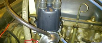
The DAAZ-2105 carburetor starts working from the starting system. Using the choke lever, the channel is closed, and the throttle valve is slightly opened to a certain clearance.
At the same time, the engine receives the richest possible mixture - it is supplied from the float chamber through the jets of the main metering system and the small diffuser. Then the engine starts. To prevent a large amount of liquid fuel from entering the cylinders, the vacuum actuates the starting device membrane and the air damper opens slightly.
Adjusting the carburetor trigger 2105, 2107 Ozone
achieve precise setting of the gaps (A, B) between the walls of the mixing chamber and the edges of the carburetor air damper and the throttle valve of the first chamber. As a result, normal operation of the starting system is ensured and the engine starts reliably.
Very often, if the starting device is faulty or not adjusted, a cold car engine either does not start at all, or starts, but with difficulty.
Starter Adjustment Tools
1. Slotted screwdriver. To rotate the adjustment screw.
2. Round probes, drills or pieces of wire (diameter 5.0, 0.8, 0.9 mm). For measuring starting gaps.
3. Tachometer (multimeter, autotester, operating in tachometer mode). To adjust the speed without removing the carburetor from the engine.
Checking the operation of the carburetor starting device 2105, 2107 Ozone
We will need an assistant to check. Remove the air filter cover. The assistant starts the engine, and we look from above at the carburetor air damper. At the first flashes in the engine cylinders, the air damper should open slightly at a certain angle (starting gap).
The gap between the edge of the air damper and the wall of the first chamber of the carburetor 2105, 2107 Ozone formed immediately after starting the engine
If this does not happen, then most likely the starter is not adjusted or its diaphragm is damaged. The diaphragm can only be checked by removing the cover of the trigger housing. If it is damaged, then replace it with a new one. If it is intact, tighten the screws securing the starter cover more firmly, since it is possible that due to its loose fit, the seal of the housing is compromised.
Preparatory work
Remove the air filter housing.
Adjusting the starting device on a removed carburetor
To begin with, we set the gap (B) , which is necessary to ensure the enrichment of the fuel mixture when starting the engine, when additional volume is supplied through the slightly open throttle valve, facilitating the first engine speeds.
This is the gap between the upper edge of the throttle valve of the first chamber of the carburetor and its wall.
Removing the carburetor from the car engine
“Removing carburetor 2105, 2107 Ozone from a car engine.”
We turn the lever of its air damper and close it completely
Thus, we cock the starting device and bring it into working condition.
Turn the choke lever counterclockwise until it stops (cock the carburetor trigger)
Top view of a closed air damper. It covers the cross section of the first chamber completely, without gaps.
The air damper of the carburetor 2105, 2107 Ozone must be completely closed when the starter is cocked
With the air damper fully closed, the throttle valve of the first chamber should open slightly.
Turn the carburetor over and measure the gap between the edge of the throttle valve of the first chamber and the chamber wall
This gap (B) for carburetors 2105-1107010, 2105-1107010-10, 2105-11070-20 = 0.7, 0.8 mm, for carburetors 2107-1107010, 2107-1107010-20 = 0.85, 0.90 mm. We take measurements with a probe, drill or a piece of wire of the required diameter.
Measuring the starting gap “B” on the removed carburetor using a drill
If it is not correct, adjust it by bending the throttle linkage with pliers and a small hammer. Just before bending it is advisable to heat it.
When bending the throttle valve drive rod of the 1st chamber, the gap “B” increases, when straightening it decreases
Now we adjust the gap (A )
between the lower edge of the air damper and the wall of the air duct. It occurs immediately after starting the engine, when the diaphragm mechanism is activated.
Completely close the air damper of the first chamber
We cock the starting device again.
The starter is cocked - the air damper is completely closed
We press the starter rod, pushing it inside the housing
This is how we simulate the effect of rarefaction.
Forced movement of the carburetor trigger rod 2105, 2107 Ozone deep into the body
The rod pulls a rod inserted into its slot, which in turn, acting on the lever, slightly opens the air damper
We measure the gap that appears (A) . It should be within 5.0 - 5.5 mm. We carry out the measurement using a probe or drill.
Starting gap “A”, formed after the rod moves deep into the starting device housing
If necessary, this gap can be increased or decreased using a slotted screwdriver by screwing in or out a screw inserted into the end part of the diaphragm mechanism
Access to the screw that regulates the amount of movement of the rod
The screw is closed on the outside with a screw plug. It needs to be turned out.
Adjusting the carburetor starting device 2105, 2107 Ozone without removing the carburetor from the engine
See “Adjusting the Ozone carburetor trigger without removing it from the car engine.”
Transitional system, GDS
When the driver presses the gas pedal, the throttle valve opens slightly. The engine receives fuel due to vacuum through the small diffuser of the first chamber and the jets of the main metering system. At the same time, the GDS is not yet fully operational, but the idle system is still working.
If you press the gas sharply, the accelerator pump will start. It injects a portion of gasoline through its spout directly into the manifold. The pump is designed to eliminate failures when starting and accelerating the car.
A further increase in speed entails an increase in vacuum. The force begins to retract the membrane, and it opens the draft of the secondary chamber. The diffuser and jets of the second chamber come into operation.
To prevent failures when the second chamber is fully opened, the DAAZ-2105 1107010 carburetor is equipped with a transition system. It is designed similarly to the idle system. But the hole for supplying the combustible mixture is located higher than the closed throttle of the second chamber.
Setting up the Ozone carburetor
Often the “seven” is equipped with an “Ozone” carburetor. This unit is configured according to a certain scheme. It should be noted that replacing a needle valve involves adjusting the level of the substance in the corresponding chamber.
Having disassembled the VAZ 2105 carburetor cover, you need to make sure that the float is in a free position and can easily rotate on its axis. There are no holes or dents and the bedroom wall is not touching. The tightness of the needle valve seat is checked, including the free movement of the ball in the corresponding hole.
We are rebuilding the minimum
When adjusting the Ozone carburetor, it is necessary to keep the cover in a vertical position with the fitting facing up. Please note that the gap between the float and the gasket should be 6.5 mm. The important point in this matter is the contact of the float tongue and the ball. If necessary, the gap is adjustable. To do this, the tongue is bent, and the area in contact with the ball must be located perpendicular to the axis of the valve. If the above conditions are met, the roof is mounted in its original position.
Adjusting the Ozone carburetor for models 2107-1107010-20 involves adjusting the pneumatic actuation of the throttle valve of the 2nd chamber. This procedure is performed when replacing a rod or diaphragm actuator. The lock washer is removed and the rod is disconnected. After turning the 2nd chamber throttle to a vertical position, it will need to be pressed all the way down. Then the locknut on the rod is loosened. The bushing is held in place with a wrench. In this position, the rod is rotated or rotated until the lever pin aligns with the hole in the rod. The last block is put on the pin and secured with a lock washer. The lock nut is then tightened.
When adjusting the Ozone carburetor (as well as the 2105 carburetor), you must sharply press the accelerator pedal and then release it smoothly. If this process is performed correctly, the engine will be able to increase the crankshaft speed without failure. If the speed decreases, the engine should not stop. In this case, the crankshaft rotation speed is increased by a screw. The last step in the process is installing the end cap. Having figured out how to adjust the 2105 carburetor, you can get to work.
Dampers
Primary adjustment comes down to adjusting the cable on the trigger mechanism and adjusting the accelerator pedal traction. It is easy to adjust the thrust - the plastic tip is placed approximately opposite the hinge, twisting it along the thread. To secure, tighten the nut 10 mm.
The choke drive cable is adjusted as follows. The choke lever in the cabin is pushed in all the way, and the air damper must be fully open. The cable is threaded through the eyes, and the end is inserted into the corresponding hole in the clamp. While holding the latch, tighten the bolt with a wrench. When pulling and retracting the choke, you need to make sure that the damper opens and closes completely.
Next, check how the throttle of the second chamber opens. The membrane and rod must be in such a state that their stroke is sufficient to fully open the damper. If the stroke is not enough, then unscrew the nut that is on the rod and adjust the length.
Why does the cylinders flood?
Also look carefully at the spark plugs; if they have heavy carbon deposits on them, the engine will run unstably. But if a lot of gasoline enters the combustion chambers, then most likely it is necessary to adjust the level in the float chamber.
In this case, the cylinder head will have to be repaired. If the engine runs unstable, as well as stops at high speeds, look for a fault first of all not in the carburetor, but in the fuel pump and its drive. But you need to look at the carburetor of the VAZ 2105; adjustment will not hurt it.
Idling
The DAAZ-2105 1107010 carburetor is adjusted as follows. The mixture toxicity screw must be unscrewed approximately 3.5 turns. The quantity screw is unscrewed 7 turns. Using a starting device, the power unit is started. If the speed is high, you can reduce it by tightening the quantity screw. The engine needs to be warmed up.
Next, remove the choke completely and adjust it using a screw to approximately 900 revolutions. After this, turn the quality screw. They twist it and achieve the highest speeds. You need to find the position at which the speed will be maximum. This is the correct position. With this position of the screw, the fuel burns as efficiently as possible and the idle speed is smooth. And if you rotate it further, the engine will become unstable.
Many people recommend adjusting the idle speed of the DAAZ-2105-20 carburetor using spark plugs. When the engine is idling, regardless of the quality of the mixture, the spark plugs will be black, so you should not trust this method.
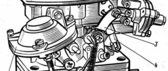
CARBURETOR 2105-1107010
The VAZ-2105 car is equipped with a 2105-1107010 emulsion-type carburetor, two-chamber, with a falling flow. Has a balanced float chamber (Fig. 2-81),
Rice. 2-81. Diagram of the main dosing system of the carburetor and econostat (the econostat spray is located in the second chamber of the carburetor. In the diagram it is conventionally shown in the first chamber):
1 — econostat emulsion jet; 2 — emulsion channel of the econostat; 3 — air jet of the main dosing system; 4 — econostat air jet; 5 — econostat fuel jet; 6 — needle valve; 7 — float axis; 8 — locking needle ball; 9 — float; 10 - float chamber; 11 — main fuel jet; 12 - emulsion well; 13 - emulsion tube; 14 — axis of the throttle valve of the first chamber; 15 — spool groove; 16 — spool; 17 — large diffuser; 18 — small diffuser; 19 - sprayer
two main metering systems, an enrichment device (econostat) with a pneumatic drive, a crankcase gas suction system behind the throttle valve, a pipe for supplying vacuum to the vacuum regulator of the ignition distributor, an autonomous idle system with a forced idle economizer (Fig. 2-82) with electronic control by engine crankshaft rotation speed.
Rice. 2-82. Diagram of the carburetor idle system 2105-1107010:
1 — throttle body; 2 - throttle valve of the first chamber; 3 - holes for transition modes; 4 - adjustable hole; 5 - air supply channel; 6 — economizer needle; 7 — forced idle economizer housing; 8 - economizer cover; 9 — hose connecting the economizer to the pneumatic valve; 10 — adjusting screw for the amount of mixture; 11 - adjusting screw for the composition (quality) of the mixture; 12 — emulsion channel of the idle system; 13 — carburetor body cover; 14 - air damper; 15 — air jet of the idle system; 16 — fuel jet of the idle system; 17 — fuel channel of the idle system; 18 - emulsion well; 19 — pneumatic valve; 20 - hose going to the inlet pipe
The throttle valve of the second chamber has a pneumatic drive (Fig. 2-83), the air damper has a diaphragm starting device for starting a cold engine (Fig. 2-84). The accelerator pump (Fig. 2-85), a diaphragm type, mechanically driven, supplies fuel to the first chamber.
Rice. 2-83. Diagram of the carburetor throttle valve drive 2105-1107010:
1 — pneumatic drive jet located in the diffuser of the first chamber; 2 — throttle valve drive lever; 3 - lever rigidly connected to the axis of the throttle valve of the first chamber; 4 - lever limiting the opening of the throttle valve of the second chamber; 5 — pneumatic drive jet located in the diffuser of the second chamber; 6 - lever connected to lever 9 through a spring; 7 — axis of the throttle valve of the second chamber; 8 — pneumatic drive rod; 9 — throttle control lever of the second chamber; 10 — channel for supplying vacuum to the pneumatic drive; 11 - rod bushing; 12 — pneumatic drive of the throttle valve of the second chamber
Rice. 2-84. Carburetor trigger diagram 2105-1107010:
1 — air damper control lever; 2 - air damper; 3 — air pipe of the first chamber; 4 - traction; 5 — starting rod; 6 - diaphragm; 7 - adjusting screw; 8 - cavity communicating with the throttle space; 9 — telescopic rod; 10 — throttle valve drive lever; 11 — sector (antenna); 12 — axis of the throttle valve of the first chamber; 13 — lever on the axis of the throttle valve of the first chamber; 14 - lever connected to the air damper
Rice. 2-85. Carburetor accelerator pump diagram 2105-1107010:
1 — screw valve; 2 - sprayer; 3 - fuel channel; 4 - bypass jet; 5 - float chamber; 6 — accelerator pump drive sector; 7 — drive lever; 8 — return spring; 9 - diaphragm cup; 10 — pump diaphragm; 11 — inlet ball valve; 12 — pump vapor chamber
Carburetor calibration data is given in Table 2-6.
Adjusting the engine idle speed
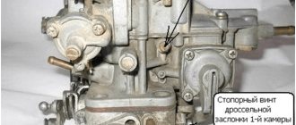
Engine idle speed adjustment elements include screw 2 (Fig. 2-86), which determines the mixture composition, and screw 1, which regulates the amount of mixture.
Rice. 2-86. Carburetor idle speed adjustment screws 2105-1107010:
1 — mixture quantity screw; 2 - mixture quality screw
CARBURETOR CALIBRATION DATA 21-5-1107010
Table2-6
| Indicators | 1st camera | 2nd camera |
| Calibration number of the mixture sprayer | 3,5 | 4,5 |
| Diameter of the main fuel jet, mm | 1,07 | 1,62 |
| Diameter of the main air jet, mm | 1,70 | 1,70 |
| Emulsion tube calibration number | f15 | f 15 |
| Diameter of the idle fuel jet, mm | 0,50 | 0,60 — |
| Diameter of the idle air jet, mm | 1,70 | 0,70 |
| Diameter of the accelerator pump nozzle hole, mm | 0,40 | — |
| Accelerator pump bypass jet diameter | 0,40 | — |
| Accelerator pump performance for 10 full strokes, cubic cm. | 7 + 25% | |
| Econostat fuel jet diameter, mm | — | 1,50 |
| Econostat air jet diameter, mm | — | 1,20 |
| Diameter of the emulsion jet of the econostat, mm | — | 1,50 |
| Diameter of the pneumatic drive jet of the throttle valve of the second chamber, mm | 1,20 | 1,00 |
| Diameter of the air jet of the starting device, mm | 0,70 | — |
| Distance of the float from the carburetor cover with gasket, mm | 6,5 + 0,25 | |
To ensure that the owner does not violate the factory settings, restrictive plastic bushings are pressed onto the screws, allowing the screws to be turned only half a turn.
If it is not possible to adjust the CO content in the exhaust gases with the bushings, then by unscrewing the screws, break the heads of the bushings, unscrew the screws, remove the bushings from them and screw the screws back into the carburetor.
Note. Blue bushings are installed at the factory, and red bushings are installed at service stations.
Idle speed adjustment is carried out on a warm engine (coolant temperature 90 - 95 ° C and oil temperature 75 - 90 ° C) with adjusted gaps in the valve timing mechanism and with a correctly adjusted ignition timing.
Make adjustments in the following order:
- Using screw 1 (see Fig. 2-86), set the crankshaft rotation speed to 820 - 900 using the stand tachometer.
- use screw 2 to achieve a CO concentration (reduced to 20 ° C and 1013 GPa (760 mm Hg)) in the exhaust gases within 0.5 - 1.2% at a given position of screw 1;
- Use screw 1 to restore the crankshaft speed to 820 - 900 m
- if necessary, use screw 2 to restore the CO concentration to 0.5 - 1.2%;
- Press restrictive plastic bushings onto the screws, orienting the splines of the bushings relative to the mounting lugs, as shown in Fig. 2-87.
Rice. 2-87. Installation of restrictive bushings on the carburetor idle speed adjustment screws 2105-1107010;
a - on the screw for the amount of mixture; c - on the mixture quality screw
Setting the fuel level in the float chamber
The fuel level required for normal operation of the carburetor is ensured by the correct installation of serviceable elements of the shut-off device (Fig. 2-88).
Rice. 2-88. Setting the fuel level in the carburetor float chamber:
1 — carburetor cover; 2 — needle valve seat; 3 - emphasis; 4 - needle valve; 5 — locking needle ball; 6 — valve needle pull-out fork; 7 — float bracket; 8 - tongue; 9 - float; 10 - gasket
The distance between the float and gasket 10 adjacent to the carburetor cover (size A) should be 6.5 ± 0.25 mm; This size is adjusted by bending tongue 8. In this case, the supporting surface of the tongue must be perpendicular to the axis of the needle valve and must not have nicks or dents.
Perform inspection with caliber 67.8151.9505. Hold the housing cover vertically so that the tongue 8 of the float lightly touches the ball 5 of the needle valve 4 without recessing it.
Adjust the maximum float stroke of 8±0.25 mm by bending the stop 3. The valve needle pull-out fork 6 should not interfere with the free movement of the float.
When installing the carburetor cover, check that the float does not touch the walls of the float chamber.
Note. The float installation should always be checked when replacing a float or needle valve; In the latter case, the valve seal must also be replaced.
Adjusting the carburetor drive
With pedal 16 fully pressed (Fig. 2-89)
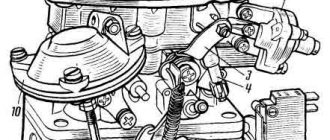
Rice. 2-89. Carburetor control drive 210501107010:
1 — air damper control rod handle; 2 and 17 - seals; 3 — air damper drive rod; 4 and 14 - return squads; 5 - return spring fastening screw; 6 — transverse thrust; 7 — intermediate lever; 8 — longitudinal thrust; 9 - rod fastening bracket; 10 — bracket for mounting the roller; 11 and 13 — levers; 12 - roller; 15 — lock washer; 16 - throttle control pedal
The throttle valve of the first chamber must be fully open and the throttle lever must not have additional travel. When the pedal is released, the throttle valve should be completely closed. If this is not the case, then the position of the pedal and the throttle valve can be coordinated by changing the length of rod 8, rolling or screwing its tip.
At the same time, check and, if necessary, adjust the length of rod 6. The center-to-center distance of its tips should be 80 mm.
Rod 3 of the air damper drive and its shell must be secured so that when handle 1 is fully extended, the damper is completely closed, and when the handle is recessed, it is completely open.
Removing and installing a carburetor on a car
Remove the air filter.
Disconnect rod 6 from the throttle drive lever (see Fig. 2-89) and return spring 4. Disconnect rod 3 of the air damper drive from the carburetor.
Disconnect the hoses from the carburetor. Close the end of the fuel supply hose with a plug to prevent fuel leakage.
Remove the carburetor. Close the inlet of the inlet pipe with a plug. Install the carburetor in reverse order. After installation, adjust the carburetor throttle valve drive, as well as the engine idle speed.
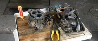
Disassembling the carburetor
Remove the return clamp 8 (Fig. 2-90). Undo the cotter pin and disconnect the connection rod with the three-arm lever 3 from the throttle lever of the first chamber.
Rice. 2-90. View of carburetor 2105-1107010 from the throttle valve drive side:
1 - air damper; 2 — starting device; 3 — three-arm air damper control lever; 4 — telescopic rod; 5 - microswitch; 6 — throttle valve drive lever; 7 - lever limiting the opening of the throttle valve of the second chamber; 8 — return spring; 9 — pneumatic drive rod; 10 — pneumatic drive of the throttle valve of the second chamber
Disconnect rod 9 of the pneumatic drive from the throttle valve drive lever of the second chamber.
Squeezing the telescopic rod spring 4, disconnect it from the three-arm lever 3.
After unscrewing the fastening screws, disconnect the cover with the gasket from the carburetor body, being careful not to damage it and the float.
After unscrewing the fastening screws, disconnect the throttle body from the carburetor body, being careful not to damage the adapter bushings of the carburetor fuel-air channels pressed into the body and the bushing sockets. Carefully remove the thermal insulation pad.
DISASSEMBLY OF THE CARBURETOR HOUSING COVER
Using a mandrel, carefully push the float 16 axis (Fig. 2-91) out of the racks (push it towards the rack with the cut) and remove the axis with smooth-nose pliers. Taking care not to damage the float tongues, remove it with needle valve 15.
Rice. 2-91. Carburetor cover parts 2105-1107010:
1 - adjusting screw; 2 — starting device cover; 3 - spring; 4 - diaphragm; 5 — diaphragm rod; 6 — starting device housing; 7 - telescopic rod; 8 — air damper axis; 9 - air damper; 10 — carburetor cover; 11 - gasket; 12 - filter; 13 — filter plug; 14 — needle valve seat; 15 — needle valve; 16 — float axis; 17 — float; 18 — gasket; 19 — starting device thrust,
Remove the gasket 11 of the cover, unscrew the seat 14 of the needle valve, unscrew the plug 13 and remove the fuel filter 12.
Disconnect the telescopic rod 7 and the rod 19 of the starter drive from the lever of the air damper axis 8.
Unscrew the two screws securing the housing 6 of the starting device and remove it.
Unscrew the three screws securing the device cover 2 and remove the cover with the adjusting screw 1 and spring 3. Remove the diaphragm 4.
DISASSEMBLY THE THROTTLE BODY (Fig. 2-92)
Rice. 2-92. Carburetor throttle body parts 2105-1107010:
1 — throttle valve drive lever; 2 - lever limiting the opening of the throttle valve of the second chamber; 3 - bushing; 4 — link lever with the air damper; 5 - lever mounted on the axis of the throttle valve of the second chamber; 6 - spring; 7 — lever connected to the pneumatic drive; 8 — throttle body; 9 — return spring of the first throttle valve; 10 — axis of the second throttle valve; 11 — throttle valves; 12 — axis of the first throttle valve; 13 — restrictive bushings; 14 — idle mixture adjustment screw; 15 - sealing ring; 16 — gasket; 17 — forced idle economizer housing; 18 — economizer cover; 19 — screw for adjusting the amount of idle mixture; 20 — economizer diaphragm; 21 — economizer needle; 22 — needle seat; 23 — microswitch mounting bracket; 24 - microswitch; 25 - spool; 26 — spool spring; 27 - lever mounted on the axis of the first throttle valve
Break the heads of the limiting bushings 13, unscrew the adjusting screws 14 and 19 and remove the remaining bushings.
Unscrew the screws and remove the forced idle economizer cover 18, diaphragm 20 with needle 21 , economizer body 17 and seat 22. At the same time, remove bracket 23 with microswitch 24.
Bend the lock washer's tendril and unscrew the nut securing the levers to the damper axis of the first chamber.
Remove the lock washer, levers 1,2,4,27 with washers and bushing 3 from the damper axis of the first chamber, and then the spool pressure spring 26 and spool 25.
Unscrew the nut securing the levers on the throttle valve axis of the second chamber, remove the levers with washers and spring.
DISASSEMBLY OF THE CARBURETOR HOUSING
Unscrew the two screws and remove the pneumatic actuator of the throttle valve of the second chamber. Unscrew the three screws securing the cover 4 (Fig. 2-93) of the pneumatic actuator and remove it, the spring and the diaphragm 3 with the rod.
Rice. 2-93. parts 2105-1107010:
1 — rod of the pneumatic drive of the second throttle valve; 2 - pneumatic drive housing; 3 - diaphragm; 4 — pneumatic drive cover; 5 — fuel jet of the transition system of the second chamber; 6 — fuel nozzle body; 7 — small diffuser of the second chamber; 8 — accelerator pump nozzle; 9 — screw valve of the accelerator pump; 10 — main air jet of the second chamber; 11 — emulsion tube of the second chamber; 12 — main air jet of the first chamber; 13 — emulsion tube of the first chamber; 14 - main fuel jet of the second chamber; 15 — main fuel jet of the first chamber; 16 — accelerator pump adjusting screw; 17 — fuel jet of the idle system; 18 — fuel nozzle body; 19 - return spring of the accelerator pump; 20 — accelerator pump diaphragm; 21 — accelerator pump cover; 22 — small diffuser of the first chamber; 23 — lever return spring; 24 — three-arm lever for air damper drive; 25 — connection rod with the throttle valve; 26 — bracket for the throttle valve return spring
Unscrew the screw securing the air damper control lever 24, remove the bracket 26, the lever and the spring 23, and disconnect the rod 25 from the lever.
Remove the screws securing the cover 21 of the accelerator pump with return spring 19.
Unscrew the main air jets 10 and 12, turn the body over and, lightly tapping it, shake out the emulsion tubes 11 and 13 from the wells.
Unscrew the housings of jets 6 and 18 and remove them together with jets 5 and 17.
Unscrew the valve-screw 9 and remove the accelerator pump nozzle 8 with gaskets, unscrew the accelerator pump adjusting screw 16.
Take out the small diffusers 7 and 22, unscrew the main fuel jets 14 and 15.
CLEANING AND CHECKING TECHNICAL CONDITION
Fuel filter. Wash the filter in gasoline and blow with compressed air. Check the condition of the filter and the conical sealing ring of the filter plug. If the filter or plug is damaged, replace it with a new one.
Float mechanism. Wash the parts in acetone or gasoline. The float must not be damaged or distorted in any way. The mass of the float should be 11 - 13 g. The sealing surfaces of the needle valve and its seat must not be damaged to impair the seal of the valve. The valve should move freely in its seat, and its ball should move freely and not hang up. Replace faulty parts with new ones.
Carburetor cover. Clean the cover and all holes and channels from dirt and oil. Wash the lid in gasoline or acetone and blow with compressed air. Inspect the sealing surfaces of the cover. If damage is found, replace the cover with a new one.
Starting device. Clean all parts of the starting device, rinse with gasoline and blow with compressed air. Inspect the parts, replace damaged ones.
Jets and emulsion tubes. Clean the jets and emulsion tubes from dirt and resinous deposits. Wash them with acetone or gasoline and blow with compressed air.
WARNING
It is not allowed to clean the jets with metal tools or wire, and also to wipe the jets and other parts of the carburetor with cotton wool, cloth or rags, as lint can clog the fuel-emulsion path.
If the blockage is severe, you can clean the jets with a soft wood needle moistened with acetone.
Carburetor body. Clean the housing from dirt and oil. Wash the housing and its channels with gasoline or acetone and blow with compressed air. If necessary, clean the channels and emulsion wells with special reamers. Inspect the sealing surfaces of the housing; if they are damaged, replace the housing with a new one.
Acceleration pump. Clean the pump parts, rinse them and blow them with compressed air. Check the ease of movement of the ball in the screw valve 9 (see, Fig. 2-93) and the condition of the sealing surfaces and gaskets.
Check the ease of movement of the moving parts of the pump (lever, roller, diaphragm parts). Jams are not allowed. The diaphragm must be intact, without deformation. Replace damaged parts with new ones.
Pneumatic drive of the throttle valve of the second chamber. Clean the parts, rinse and blow with compressed air. Check the condition of the diaphragm; it should not be damaged.
Throttle body and its parts. Clean the parts and rinse them with gasoline or acetone. Inspect the parts, replace damaged ones.
CARBURETOR ASSEMBLY
The carburetor is assembled in the reverse order of disassembly. In doing so, pay attention to the following:
• the float must rotate freely on its axis without touching the chamber walls;
• the needle valve should slide freely in its seat without distortion or jamming, and the valve guide should not interfere with the movement of the float tongue.
To avoid mixing up the jets of the first and second chambers during assembly, pay attention to the markings of the jets and when installing them, follow the calibration data table given at the beginning of the chapter.
The main air jets 3 (see Fig. 2-81) have a marking on the upper plane of the jet head (for example, “170”), which indicates the diameter of the jet hole (1.70 mm).
For main fuel jets, 11 numbers are printed on the side surface (“107”) and also indicate the diameter of the nozzle hole (1.07 mm).
The emulsion tubes 13 of the first and second chambers of the carburetor of this car are the same. However, they may be different on other car models. Therefore, on the cylindrical surface, at the bottom of the tubes, numbers are applied (for example, “F 15”), which indicate the calibration number of the tube.
On small diffusers 18 there are also numbers (for example, “4.5”) indicating the calibration number of the atomizer hole.
For idle fuel jets, numbers are stamped on a cylindrical band (for example, “50” or “60”) and indicate the hole diameter (0.50 or 0.60 mm).
Installation of the pneumatic drive of the throttle valve of the second chamber. Attach rod 8 (see Fig. 2-83) to lever 6 on the axis of the throttle valve of the second chamber in the following order:
• turn the throttle valve of the second chamber to a vertical position;
• press the rod 8 of the pneumatic actuator all the way and, holding the sleeve 11 from turning, turning the rod out or in, adjust its length so that the hole in the tip of the rod 8 is opposite the pin on the lever 6;
• put rod 8 on lever pin 6 and secure with lock washer;
• secure rod 8 with a locknut, holding bushing 11 from turning with another wrench.
ADJUSTING AND CHECKING THE CARBURETOR AFTER ASSEMBLY
Position of the throttle valves. The partial opening of the throttle valve of the first chamber, at which the upper tendril of lever 3 (Fig. 2-94a) comes into contact with lever 2, should be 6 ± 0.1 mm.
This size can be adjusted by bending the upper tendril of lever 3. Fig. 2-94. Adjusting the carburetor throttle valve positions 2105-1107010:
a - partial opening of the throttle valve of the first chamber; c - full opening of the throttle valves; 1 — lever on the throttle axis of the second chamber; 2 - lever limiting the opening of the throttle valve of the second chamber; 3 - lever rigidly connected to the axis of the throttle valve of the first chamber; 4 — damper drive lever; 5 — throttle valve of the first chamber; 6 - throttle valve of the second chamber
Full opening of the throttle valves is checked by turning their drive levers to the stop position. The maximum opening value of the throttle valve of the first chamber (13±0.5 mm) is adjusted by bending the lower tendril of lever 3.
The maximum opening value of the throttle valve of the second chamber (15±0.5 mm) is adjusted by screwing in or unscrewing the pneumatic drive rod.
The position of the microswitch is adjusted when the air damper is open.
Microswitch 3 (Fig. 2-95) should turn off when lever 2 is turned clockwise until it stops. When turning lever 2 from its original position counterclockwise until it stops at the antenna A of lever 1, the microswitch should turn on. Rice. 2-95. Adjusting the microswitch position:
1 - lever mounted on the axis of the throttle valve of the first chamber; 2 — throttle valve drive lever; 3 - microswitch; A - lever antenna 1
To adjust the moment of turning the microswitch on and off, loosen the screws securing it to the bracket and turn it relative to the top screw to the required position. Then tighten the mounting screws.
Starting device. When turning lever 1 (Fig. 2-96) counterclockwise until it stops, the air damper should be completely closed. Moreover, in this position of the lever, the end of the rod 3 should be at the end of the groove of the rod 4 of the starting device, but not move the rod. This requirement is met by bending rod 3.
Rice. 2-96. carburetor starter drive 2105-1107010:
1 — three-arm lever for air damper drive; 2 - air damper; 3 — thrust of the starting device; 4 - rod; 5 - adjusting screw; 6 — throttle valve of the first chamber; 7 — throttle drive rod
With the air damper completely closed, the throttle valve of the first chamber should be slightly open by 0.7-0.8 mm (gap C is the distance between the damper and the chamber wall at the location of the idle air system vias). This gap is adjusted by bending rod 7.
A fully closed air damper should be opened 5 (+0.5) mm (gap B) by the trigger rod when moving it manually to the right until it stops. This value is adjusted with screw 5.
The fuel supply by the accelerator pump is checked during ten full strokes (turns) of lever 4 (see Fig. 2-94) of the throttle valve drive. The fuel released from the pump nozzle during these ten strokes is collected in a beaker. Its volume should be 5.25-8.75 cc.
Before starting the test, make ten test strokes with the lever to fill the accelerator pump channels.
The tightness of the needle valve is checked on a stand, which supplies fuel to the carburetor at a pressure of 30 kPa (3 m of water column). After setting the fuel level in the test tube of the stand, it is not allowed to drop for 10-15 s. If the fuel level in the test tube decreases, this indicates a fuel leak through the needle valve.
CHECKING THE OPERATION OF THE FORCED IDLE ECONOMIZER
Checking the economizer. Check the operation of the economizer by disconnecting the wires from the pneumatic valve with the engine running. The engine should stall.
Check the tightness of the economizer diaphragm by supplying air at a pressure of 0.15 MPa (1.5 kgf/cm 2 ) into the economizer fitting. No pressure drop is allowed within 10 s.
Checking the pneumatic valve. Turn on the ignition and use a voltmeter or test lamp to check whether there is voltage at the pneumatic valve connectors. Check operation by disconnecting and reconnecting wires to the air valve plugs. When the valve is activated, a characteristic click should be heard.
Start the engine and disconnect the wires from the air valve. The engine should stall.
The valve must be sealed when air is supplied with an excess pressure of 0.085 MPa (0.85 kgf/cm 2 ) to the unmarked fitting or when a vacuum of 0.085 MPa (0.85 kgf/cm 2 ) is supplied to fitting “1”. Plug connector “2” when checking for leaks.
When a vacuum of 0.085 MPa (0.85 kgf/cm 2 ) is supplied to fitting “1”, the valve should open when an electric voltage of 12 V is supplied and close when the voltage is removed.
Current consumption at a voltage of 12 V is 0.375 A. Minimum operating voltage at a temperature from -40 to 100 ° C, a vacuum at fitting “1” of 0.085 MPa (0.85 kgf/sq. cm) or excess pressure at an unmarked fitting of 0.085 MPa (0.85 kgf/sq.cm), with closed fitting “2” there should be 9 V.
Checking the microswitch. Disconnect the wires from the microswitch and, using an ohmmeter or a test lamp with a power of no more than 5 W with a battery, check the operation of the microswitch by pressing and releasing its lever. When you press the lever, the microswitch contacts should open (the control lamp should go out). When the lever is free, the microswitch contacts must be closed (the control lamp is on).
Check the microswitch setting as above and adjust if necessary.
Checking the pneumatic valve control unit is described in the “Electrical Equipment” section.
>
Now about the setup itself
Maintaining the required fuel level in this device is ensured by a float mechanism.
Setting the float mechanism
- Start the car engine and let it idle for 2-3 minutes;
- Remove the carburetor cover;
- Check the fuel level in the float chamber. It should be 28 mm.
In case of deviation, we perform the following actions:
- Measure and adjust the distance between the cover gasket and the float when the float tongue touches the needle valve ball. It should be 6.5±0.25 mm. Adjust by bending the tongue;
- Check the maximum valve needle travel. It should be 8 mm. To check, it is necessary to measure the distance between the cover gasket and the maximum retracted float. It should be 14±0.5 mm. The deviation is eliminated by acting on the bracket;
- Visually check that the tongue of the needle valve axis is perpendicular and that the float is parallel to the bottom plane of the cover. If there are any violations, correct them.
If all of the above steps fail to achieve a stable fuel level (28 mm) in the float chamber, then the needle valve must be replaced.
Adjusting the starting device of the VAZ 2105 carburetor
- Using the thrust handle located in the cabin, close the air damper;
- Check that the rod shank is at the end of the carburetor trigger rod groove. If there is a violation, correct it by bending the rod;
- Remove the cover and measure the gap between the edge of the air damper and the chamber wall with the starter rod recessed (we recess the rod using a screwdriver with the rod disconnected). It should be 5.0-5.5 mm. We adjust by rotating the adjusting screw of the starting device.
How to install the unit in place
You can assemble and reinstall the carburetor in the same way as you disassembled it, performing all the steps in reverse order.
- The carburetor is installed in its place, the mounting bolts are tightened.
- The pipes through which fuel is supplied are attached. The gas cable is connected to the throttle lever.
- The wiring is attached.
- A vacuum hose is connected to the ignition distributor, and the EPHH limit switches are combined.
- After installing the carburetor, it is adjusted.
Video: installing a carburetor on a VAZ
It is not so difficult to independently remove, disassemble, clean and reinstall the carburetor in the VAZ 2107 and 2106. The main thing is not to be intimidated by the huge number of hoses, valves, parts and dirt and strictly follow the instructions.
If you find an error, please select a piece of text and press Ctrl+Enter.