Any mechanism must have impact organs, as well as controls. The car clutch is no exception in this regard. Designed for short-term separation of the transmission and engine, it is an integral part of any vehicle and serves to ensure the ability to control the machine.
To transfer the impact from the driver to this mechanism, a hydraulic drive is usually used in passenger cars; One of the critical parts of such a device is the clutch master cylinder.
About the hydraulic drive device
To better understand what will be discussed, it is necessary to at least schematically imagine the design of such a drive. Let’s leave its purpose, structure, and role in the vehicle aside; in this case, the hydraulic drive itself is important.
Its implementation, as an example, as one of the possible options, can be seen in the figure below. This is enough to understand the structure and operation of the clutch drive, as well as to understand its role and significance in the vehicle.
Of the drive parts in the figure, it is necessary to note the following components:
- reservoir for filling brake fluid (1), which is used as a filler for the hydraulic drive;
- clutch master cylinder (2);
- hydraulic pipes (3,4,5) and hose (7);
- clutch slave cylinder (8);
- pedal (6) and return spring (9).
Features of choosing mineral oil. Can it be used in a hydraulic clutch?
Mineral oil must adapt to the harsh operating conditions in gears, because the temperature can reach +150 C. Accordingly, strict requirements are imposed on oils, since in addition to performing the function of lubricating rubbing surfaces, they play the role of a working fluid.
Thus, mineral oil must have a sufficient number of performance qualities:
- high stability over the full operational life;
- mineral oil must have intensive aeration;
- high rates of foam formation;
- mineral oil must contain anti-corrosion additives that reduce the effect of corrosion;
- the optimal level of viscosity and density that mineral oil should have. If the level and efficiency are high, the viscosity index is minimal; if it is necessary to provide a film in the area of the friction surfaces, a high viscosity index is required;
- lack of aggressiveness in relation to parts used for compaction and in comparison with other elements operating in the system.
Often in practice, a special mineral oil is used, which is made on the basis of spindle components with a low viscosity level and the presence of additives.
However, it is worth paying special attention: in modern cars, mineral oil is not used in the clutch hydraulic drive, as it can destroy the rubber structural elements. For this purpose, special DOT4 brake fluid is used. It is also unacceptable to mix brake fluids of different types.
How does a hydraulic drive work?
Without touching on the design of individual components of this mechanism, we can return to this a little later; it is enough to familiarize ourselves with its operation in a simplified manner. We will assume that the required amount of brake fluid is filled into the drive, it is in good working order and fully operational.
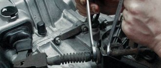
When you press the pedal (6), the force is transmitted through the rod to the clutch master cylinder (2). He perceives this force, and then transmits it through a system of tubes and hoses to the clutch slave cylinder. The latter, through the clutch fork and release bearing, disconnects the transmission from the engine.
Possible malfunctions and their diagnosis
Signs indicating malfunctions in the clutch drive can be diagnosed based on the following: - The level in the clutch reservoir has dropped significantly, this indicates that brake fluid is leaking somewhere in the system; if the connecting tubes are intact, then this may be caused by worn cuffs or piston failure in the master cylinder. — A visual inspection showed the presence of places where fluid was leaking: tubes, cuffs, etc. — When pressed, periodic failures of the pedal occur, this indicates that there is air in the clutch drive, this happens when hoses are cracked or when the level in the reservoir drops below the minimum. — When changing gears, a characteristic sound is heard in the gearbox, reminiscent of a “crunch”; the cause may be a malfunction of the piston or spring of the master cylinder.
If these signs are present, you should check all components of the clutch drive, carry out diagnostics and subsequent repair or replacement of failed parts.
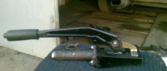
Clutch master cylinder disassembled
How does the hydraulic drive work?
The design of the clutch master cylinder can be structurally designed in different ways, but in general the principle of operation is the same in all variants. As an example, the figure below shows a sectional view of the clutch master cylinder.
Among the main details are
- (2) - a pusher connecting the mechanism to the pedal;
- (3) master cylinder;
- (4) piston;
- plugs and return spring.
The figure shows that the clutch cylinder is divided into two parts by a partition. The upper half serves to fill the hydraulic drive with fluid entering the cylinder from the tank (5) and store its required working reserve. If everything is configured and adjusted correctly, then its level should be three quarters of the working volume.
The lower part serves as a working area. In the initial state, the piston (4) is pressed against the dividing wall by a spring, a gap A is formed between the pusher and the piston, and through it the liquid fills the working area.
When you press the pedal, the pusher, moving, closes gap A, the flow from the upper part to the lower part stops, the piston begins to move, transmitting force from the driver’s foot through a system of tubes and hoses to the working cylinder.
Due to the difference in the diameters of the piston and the outlet hole, its value increases, this becomes sufficient for the clutch to operate. This drive design makes it possible to lightly press the pedal to provide the required force to operate the entire mechanism.
When the pedal is released, the piston, under the influence of the spring and the pressure existing in the system, returns to its original position, and the pusher moves there, thereby restoring free penetration of liquid between the two parts of the cylinder.
Repair
If the clutch pedal fails, in order to avoid unreasonable disassembly of the cylinder, it is worth initially bleeding the system and expelling any air that could get in when the fluid in the tank drops below the minimum permissible level. If this does not help, you should start repairing. For this case, there is a repair kit for the clutch master cylinder on sale, which, depending on the make of the car, contains the main wearing parts: cuffs, return spring, rod, retaining ring, etc.
Typical faults
Despite its simplicity, the master cylinder can also be a source of serious trouble. The most common causes of the defect may be:
- lack of working fluid;
- air entering the hydraulic drive system.
In the first case, you just need to check the liquid level in the tank; if it is insufficient, you need to add it to the set value. To avoid this, it is necessary to periodically monitor the position of the fluid in the tank during routine maintenance, as well as maintenance.
The reasons for air entering the master and slave cylinders, leading to clutch failure, may be cracks in the hoses, wear of parts, or leakage of the system at the junction of its various sections.
In order to restore the operability of the system, it is necessary to eliminate such sources of leakage and air entry into the line, the main and working cylinders, and also pump the entire system to remove air that has already entered from it. This procedure can be performed completely independently, without resorting to the help of a car repair shop. Due to the design features that the master cylinder has in different cars, it is difficult to describe this procedure correctly, although it can be briefly noted that it is carried out by pressing the clutch pedal. In this case, an additional hose is put on a special fitting or valve, through which the working fluid flows into a separate container with brake fluid.
Its level in the tank, to which the main cylinder is connected, should not fall below the set level, otherwise air may again enter. Along with the liquid, air leaves the system. When its bubbles stop releasing, we can assume that the system has been pumped and air has been removed from it. After this, everything is returned to its original state, the necessary adjustment of components and mechanisms is carried out (gaps and free movement are set).
The master cylinder is designed to transmit force from the pedal and convert its value to a value that should be sufficient to move the clutch fork. In this case, the clutch mechanism will operate and the connection between the engine and the wheels of the car will be broken.
Nuances of clutch operation
Often, drivers tend to associate unevenness and jerking when driving a car with clutch malfunctions. This logic is wrong in most cases.
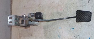
For example, when a car shifts gears from first to second, the speed drops sharply. It is not the clutch itself that is at fault here, but the clutch pedal position sensor. It is located behind the clutch pedal itself. Sensor malfunctions can be eliminated through simple repairs, after which the clutch will again operate smoothly and without jerking.
Another situation: when changing gears, the car jerks a little, and when moving away it may stall. What could be the reason? Most often, the clutch delay valve is to blame. This valve provides a certain speed at which the flywheel can engage, regardless of how quickly the clutch pedal is "thrown" in. For novice drivers, this function is necessary, because... The clutch delay valve prevents excessive wear on the clutch disc surface.
Features of ceramic clutch
The life of the clutch and the efficiency of its operation at the load limit also depend on the properties of the material that ensures the engagement of the discs. The standard composition of clutch disc linings on most vehicles includes a compressed mixture of glass and metal fibers, resin and rubber. Since the principle of operation of the clutch is based on friction, the friction linings of the driven disc are designed to operate at high temperatures, reaching up to 300-400 degrees Celsius.
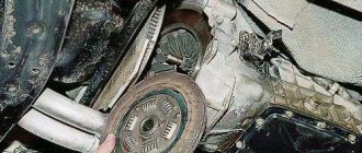
Clutch disc with ceramic friction linings
In high-performance sports cars, clutch loads are much higher than normal. Some transmissions may use ceramic or cermet clutches. The material of such overlays includes ceramics and Kevlar. Metal-ceramic friction material is less susceptible to wear and can withstand heating up to 600 degrees without loss of performance.
Manufacturers use various clutch designs that are optimal for a particular vehicle, based on its purpose and cost. The dry single-plate clutch remains a fairly effective and inexpensive design to manufacture. This scheme is widely used on passenger cars of the budget and middle classes, as well as SUVs and trucks.
Source
Types of clutch drive
On most passenger cars with a manual transmission, two types of clutch drive are installed;
- mechanical (cable);
- hydraulic.
A mechanical drive is installed mainly on passenger cars equipped with low-power power units. This type of drive has an extremely simple design and is cheap to produce. In addition, the mechanical drive is very easy to maintain and repair, since it contains a minimum number of structural elements.
Design and principle of operation of the GCS
In principle, the design of the master cylinder is quite simple:
- force is transmitted from the pedal through the pusher (10) to the rod (8);
- the piston (14) moves forward, while closing the valve (C), from which liquid from the compressible part of the cylinder can flow into the tank (1);
- the fluid in the cylinder is compressed and pushed through the fitting (19) into the hydraulic line to the working cylinder, which directly drives the fork;
- when the pedal returns to its original position, the piston returns back using a spring (18).
The operation of a hydraulic drive (no matter whether it relates to the clutch system, brake system or any other) is based on the fact that the fluid under pressure is practically not compressed, but at the same time instantly transmits force through the system of pipes to the desired point.
Clutch elements
The standard clutch used on most vehicles with a manual transmission includes the following main elements:
- The engine flywheel is the drive disk.
- Driven clutch disc.
- Clutch basket - pressure plate.
- Clutch release bearing.
- Clutch release clutch.
- Clutch fork.
- Clutch drive.
Friction linings are installed on the clutch driven disc on both sides. Its function is to transmit torque due to friction. A spring torsional vibration damper built into the disk body softens the connection with the flywheel and dampens vibrations and loads from uneven engine operation.
Layout of the clutch disc, basket and release bearing with release clutch
The pressure plate and diaphragm spring acting on the driven clutch disc are assembled into a single unit called the “clutch basket”. The clutch driven disc is located between the pressure plate and the flywheel and is connected to the transmission input shaft using splines along which it can move.
The diaphragm spring of the basket can be of either a push or pull principle of operation. The difference is in the direction of application of force from the clutch drive: to the flywheel or from the flywheel. The design feature of the extension spring allows the use of a basket whose thickness is much smaller. This makes the unit as compact as possible.
Specifications
In the specifications for the master cylinder, manufacturers indicate the following parameters:
- side of the steering wheel (left, right) – important for asymmetric mounting;
- Is there a tank included (GCS can be sold with or without a tank);
- connection method (left, top, etc.) – help with selection if non-standard parts are installed in the hydraulic drive;
- body material: cast iron, aluminum, steel, polymer;
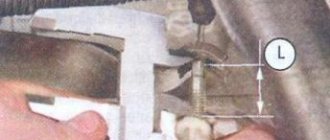
- dimensions of the body and structural elements (nozzle diameter, rod length).
These characteristics can be taken into account as auxiliary information when selecting a master cylinder for your car. Car enthusiasts pay special attention to manufacturing materials: the most common today are cast iron and aluminum, and there are also quite a few offers of cylinders with polymer bodies. Steel cases are quite rare, since steel combines high price and difficulty in processing.