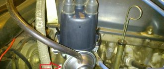
Since the beginning of car production, as the design improved, the following types of carburetors were installed: instead of the 2101-1107010 carburetor, from 1974 they began to install 2101-1107010-02; since 1977 - 2.101-1107010-03; and since 1979, Ozone carburetors 2105-1107010-20 have been installed on VAZ-2101, -21011, -21013, -2102, -21021 cars along with new ignition distributors with a vacuum ignition timing regulator. With old ignition distributors (without a vacuum regulator), a carburetor 2105-1107010-10 is installed, which is supplied as spare parts and differs from 2105-1107010-20 mainly in the absence of a vacuum selection for the vacuum regulator.
Carburetors with corresponding ignition distributors are interchangeable with each other. Basic data are given in table. 3.
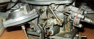
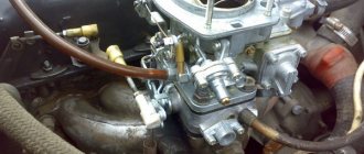
Carburetor 2105-1107010-20
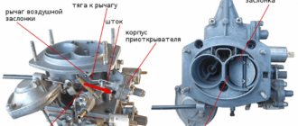
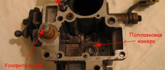
Emulsion type, two-chamber, with falling flow (Fig. 32). It has a balanced float chamber, main metering systems, an enrichment device (econostat), an idle system, a transition system, a diaphragm starting device, a spool valve for crankcase gas suction, and a pneumatic drive for the secondary chamber throttle valve.
Rice. 32. Carburetor 2105-1107010-20:
1 - air damper; 2 — diaphragm trigger; 3 — three-arm lever; 4 — telescopic rod; 5 — throttle drive lever of the first chamber; 6 - lever that limits the opening of the throttle valve of the secondary chamber; 7 — return spring; 8 - rod connecting the throttle valve of the primary chamber with a three-arm lever; 9 — pneumatic drive rod; 10 — pneumatic drive of the throttle valve of the secondary chamber.
Common causes of carburetor failure and their solutions
If one of the system elements in the carburetor fails, you may not notice it immediately. Failures appear gradually. Often, unstable idle speed is explained by a failed solenoid valve. Not all carburetors have such a device.
To test the solenoid valve, you will need to disconnect the wire connected to it. A positive contact is supplied to it from the battery. Correct wiring is indicated by a slight click.
You need to check the voltage on the wire that connects to the solenoid valve. If there is no voltage in the line, the wiring has failed. It will be necessary to completely replace the network from the ignition switch to the solenoid valve.
Unstable speed can also be observed when the spark plug electrodes are covered with a large layer of soot. The spark power is insufficient. It cannot ignite the fuel mixture. The poor condition of the spark plugs is due to incorrect carburetor settings. In this case, it supplies too much fuel to the combustion chamber.
The cause of this malfunction may be a burnt-out intake valve. It is responsible for the amount of fuel that is supplied to the combustion chamber of the engine. To ensure this, you need to adjust the carburetor. If this does not help, the inlet valve will need to be replaced.
Main dosing systems
Designed to prepare a combustible mixture of the required composition in throttling modes (low and medium engine loads). Fuel enters float chamber 4 through needle valve 28 (Fig. 33). Float 32 maintains the required fuel level. From the float chamber, fuel through the main fuel jets 34 and 45 enters the emulsion wells, mixes with the air leaving the holes of the emulsion tubes 35, 44 and entering them through the main air jets 9 and 19. Then, through the spray nozzles 12, the emulsion enters the small and large carburetor diffusers.
Rice. 33. Carburetor diagram:
1 — accelerator pump lever; 2 - adjusting screw; 3 - plug; 4 - float chamber; 5 — fuel jet of the transition system; 6 — econostat air jet; 7 — air jet of the transition system; 8 — econostat fuel jet; 9 — main air jet of the secondary chamber; 10 — econostat emulsion jet; 11 — econostat sprayer; 12 — sprayer of the main dosing system of the secondary chamber; 13 — small diffuser of the secondary chamber; 14 — valve-screw of the accelerator pump; 15 — accelerator pump nozzle; 16 — small diffuser of the primary chamber; 17 — air damper; 18 — adapter bushings; 19 — main air jet of the primary chamber; 20 - starter jet; 21 — drive rod of the starting device; 22 — starting device housing; 23 - rod; 24 — diaphragm of the starting device; 25 — adjusting screw of the starting device; 26 — idle air jet; 27 — needle valve seat; 28 — needle valve; 29 — filter; 30 — bracket with stop; 31 — damper ball; 32 — float; 33 — idle fuel jet; 34 — main fuel jet of the primary chamber; 35 — emulsion tube of the primary chamber; 36 — mixture quality adjusting screw; 37 — adjusting screw for the amount of mixture; 38 — mixing sleeve; 39 — throttle valve of the primary chamber; 40 - primary mixing chamber; 41 - secondary mixing chamber; 42 — throttle valve of the secondary chamber; 43 - non-adjustable holes of the transition system; 44 — emulsion tube of the secondary chamber; 45 — main fuel jet of the secondary chamber; 46 — accelerator pump check valve; 47 — accelerator pump bypass jet; 48 — accelerator pump diaphragm.
The main fuel jets are 34 and have a marking stamped on the side of the head (for example, 107 or 162), which indicates the diameter of the jet opening (1.07 or 1.62 mm). The main air jets 9 to 19 are marked on the upper plane (for example, 170 or 190) and also indicate the diameter of the jet holes (1.70 or 1.90 mm). A marking is applied to the cylindrical surface of the emulsion tubes 35 and 44, which indicates the calibration number of the tube (for example, 15). Small diffusers 13, 16 also have markings (for example, 3.5 and 4.5), indicating the calibration number of the atomizer hole 12.
Installing a Solex 21083 Carburetor on a Classic
Carburetor Solex 21083
to classic
.
settings
and settings
For those who decided to install a Solex 21083
At your discretion, you should know that this is a carburetor model in which the diffusers are made small. General Solex 21083 carburetor for a classic They expressed it very well. Generally speaking, it works great on engines up to 1.5L. The main feature of this carburetor, as mentioned above, is the size of the main air diffusers. Thanks to this, even at low speeds, air passes through them at high speed, and this guarantees good quality of mixture formation.
If you install Solex 21083 on an engine larger than 1.5 liters it will choke the system at high speeds. All this is because the engine simply cannot breathe the required amount of full chest air. Generally, if you don't need huge revs and you want maximum bottom end thrust, this carburetor will work just fine.
carbohydrate system solex 21083
Generally, this carburetor is usually installed on cross-section engines, but some suggest that it works great on longitudinally mounted cars, in other words, a classic.
READ Installing 2 Din Radios in Lacetti
By type, this carburetor is classified as an emulsion, which has two openable chambers. Also in the carburetor there is a conversion system, an economizer, an accelerator pump, the system is forced to remain inactive.
Installation of the fifty-third Carburetor on a VAZ-2106 from NAIL!
Today Nihol Poroshin will tell and show the main nuances of setting
53rd Carburetor
to
classic
! To each.
In principle, all this is enough for the carburetor to work successfully on a classic car. After installation, the carburetor is immediately ready for use; it only needs to be set to idle and the fuel level in the float chambers correctly set. If you put a carburetor on a 2108 engine, the mixture formation can be quite poor. In this regard, it will be necessary to replace the fuel injectors with larger ones.
Currents are always selected depending on the motor size. Moreover, everything happens the other way around; smaller engines have smaller injectors and vice versa. And the fact is that in a large engine, more air will pass through the diffuser, and at a higher speed, therefore, fuel will be sucked in more easily.
READ Replacing Speakers Ford Focus 2
It's best to choose one right away. Solex
, corresponding to the engine size.
Installation classic
As stated above, Solex carburetor 21083
set to classic is entirely possible, anyone can do it if they have the equipment skills. It's harder so adjust the carburetor to maximize its potential.
Some motorists find it advisable to grind the internal seams and various recesses in the carburetor
and then sand them down. Thus, air enters the engine with less resistance, which saves and improves traction.
The accelerator pump plays a significant role in carburetors installed on classic ones. This device must always work perfectly and without failure. Otherwise, the car will not accelerate, the carburetor will shoot due to depletion of the mixture, etc. Technicians will upgrade the accelerator pump, increasing its volume, as well as the exhaust cam grinding profile.
However, installing a Solex 21083 carburetor directly on your classic will not change anything special. These carburetors are of pretty good quality and well adjusted at the factory.
It is only important to make sure that the air and fuel filters are dirty. It is also unacceptable for gunshots or sneezes to come out of the intake manifold; this will quickly destroy any carburetor
READ Installing the Repair Kit for the VAZ 2107 Gear Lever
Econostat
Enriches the fuel mixture at maximum engine speeds and is included in the secondary chamber. Fuel from float chamber 4 (see Fig. 33) through fuel jet 8 of the econostat enters the channels located in the carburetor cover, where air from jet 6 is mixed.
The fuel-air emulsion passes through the channel through the emulsion nozzle 10 and enters through the atomizer 11 into the diffuser. The econostat comes into operation at speeds close to maximum, with the throttle valves fully open.
What kind of motor can be installed on a “penny” instead of the standard one?
One of the main types of car tuning is improving the car engine. VAZ 2101 engines are an unplowed field in this sense. Some craftsmen install turbines on them in order to increase power and traction characteristics, others change the crankshaft and bore the cylinders, and still others simply change the engine to a more powerful one.
But here it is important not to overdo it, because the car body is designed for certain loads, exceeding which can seriously harm the entire car.
Among the popular options for replacement, it is worth considering only power units that are similar in design and performance. For a penny, without any problems, you can install a 1.6 or 2.0 liter gasoline engine from the same Fiat Argenta or Polonaise.
The engine from Fiat Argenta can be installed on any classic VAZ without any special modifications
You can try the same engine from Renault Logan or Mitsubishi Galant, if you install them together with a gearbox. But the best option is a power unit from subsequent modifications of VAZs. These could be VAZ 2106, 2107, 2112 and even 2170. The engines from these cars are suitable both in size and in mounting to the gearbox.
Idle system
Prepares a rich hot mixture while the engine is idling. Fuel from the emulsion well enters the idle jet 33 (see Fig. 33) and is mixed with air entering through the air jet 26. Then, in the form of an emulsion, it passes through the emulsion channel and exits through the holes into the throttle space. The emulsion output is regulated by screw 37 for the quantity of the mixture and screw 36 for the quality of the mixture. The outlet hole above the screws ensures that there are no “dips” in engine operation when the throttle valve is opened. To prevent violation of the factory idle speed adjustment, plastic limiting bushings are pressed onto screws 36, 37, allowing the adjusting screws to be turned only half a turn. Blue bushings are installed at the factory, and red bushings are installed at service stations.
Setting idle speed
The process involves two screws that set the quantity and quality of the mixture. For high-quality settings, having a gas analyzer will not hurt. Before adjusting the carburetor on a VAZ 2106, you need to know about the restrictive plastic bushings that are pressed onto the adjusting screws. These plugs do not allow you to violate the factory settings. If this factor prevents you from setting XX normally, then you should break them out with a slotted screwdriver.
Idle speed control technology:
- With the air damper open, set the crankshaft speed screw to 800-900 rpm.
- Rotate the quality screw to set the maximum engine speed.
- Using the quantity screw, set the speed on the tachometer to 950-1030 rpm.
- Use the quality screw to set the maximum speed again.
- Repeat these operations until the speed of 950-1030 rpm does not coincide with the maximum speed set using the quality screw.
- After the moment of coincidence, return the quality screw to the position where the engine speed was 800-900 rpm.
Transition system
Ensures the absence of “dips” in engine operation at the beginning of the opening of the throttle valve of the secondary chamber and enriches the combustible mixture at maximum speed of the engine (throttle valves are open). Under the influence of vacuum at the outlet holes 43 (see Fig. 33), fuel from the emulsion well through the fuel channel, fuel nozzle 5 of the transition system, mixing with air from nozzle 7, enters the throttle space through the channel through the holes. On the cylindrical belt of the jet 5 there is a marking indicating the diameter of the jet hole.
Throttle valve adjustment
Adjusting the VAZ-2101 carburetor begins with adjusting the throttle valve. This is a simple procedure. It can be done in three stages. Manually turn the damper control lever counterclockwise. It opens completely.
The distance to the primary chamber is measured. The carburetor design suggests that this figure is 12.5-13.5 mm. If the result is different, you need to bend the rod antennae. Throttle adjustment involves determining the opening value of the throttle valve. It should be 14.5-15.5 mm. Otherwise, you will need to tighten the pneumatic drive rod.
Acceleration pump
Enriches the fuel mixture when the throttle valve is opened sharply, ensuring good vehicle response. When the throttle valve 39 is sharply opened (see Fig. 33), the cam on the valve axis presses lever 1 and acts through the pusher on the diaphragm 48, overcoming the resistance of the return spring. The diaphragm supplies fuel through the channel and injects it through the atomizer 15 into the primary mixing chamber. Part of the fuel is passed through the bypass jet 47 back into the float chamber. The bypass jet is selected in such a way that when the throttle valve is opened smoothly, all the fuel is bypassed into the float chamber. The cam profile allows for dual injection. The second injection coincides with the beginning of the opening of the throttle valve of the secondary chamber.
The sprayer 12 has a marking (for example, 40) indicating the diameter of the sprayer opening (0.40 mm).
Installing a Solex carburetor on a classic
For 30 years, while classic rear-wheel drive VAZ models were produced, their design, in contrast to style and design, was virtually unchanged by the manufacturer. Therefore, owners are trying to modernize the car themselves - introducing various components from imported cars or more technologically advanced VAZ models.
For example, many owners do not like the way Ozone and Weber carburetors work, which are not capable of providing acceptable acceleration dynamics, uniform acceleration, and acceptable fuel consumption. Despite the fact that all this is already in Solex. That is why most car owners strive to install a licensed French Solex on their classics.
You will be interested:How dangerous is the new coronavirus?
"Ozone" and "Weber" under certain road conditions excessively leaned the fuel mixture. This happened because the float moved in the float chamber when sharply entering a turn or climbing a steep mountain. Solexes do not have such a disadvantage - they are equipped with two-section float chambers, paired floats that move in other planes. The Solex device is more modern and advanced.
Which Solex to choose
Units produced by Dimitrovgradsky differ mainly in the geometry of the jets. There is a difference in the diameters of the diffusers, as well as in the size and design of the air jets. The cam profile also differs.
However, without any unpleasant consequences or modifications, absolutely any Solex from the entire series can be installed on a car for which the carburetor was never made. Many models and modifications of these carburetors were produced - they were equipped with VAZ-08, 09, AZLK-21412, ZAZ-1102. There are “Solex” for VAZ-2104, 05, 07. This all means that absolutely any unit from the mentioned line can be installed on rear-wheel drive VAZs without modifications or almost without them.
The result of tuning depends on the choice of a particular Solex. But in any case, the engine’s traction will improve and the car will accelerate smoothly. To save money, it is worth choosing the Solex modification on the Tavria - this is DAAZ-2181. If you need increased acceleration dynamics, then select DAAZ-21073. It features diffusers of larger diameter. This carburetor was created for engines with a displacement of 1.7, and after installing this Solex on a classic, you should prepare for high fuel consumption.
Solex models 2108, 21083, 21051-30 are considered by motorists to be the golden mean. The units are capable of providing better dynamic characteristics and lower fuel consumption when comparing their characteristics with Ozone.
Starting device
Ensures cold engine starting. It consists of an air damper 2 (Fig. 34) above the primary mixing chamber, a three-arm lever 1, a telescopic rod, a throttle valve drive rod 7 and a diaphragm device. Lever 1 is connected by a rod to the manual control button in the cabin under the instrument panel. When the button is pulled, the three-arm lever through rod 7 slightly opens the throttle valve of the primary chamber, and the telescopic rod, by turning the air damper lever, closes the air damper. Rod 3, connected to the air damper lever, moves along the groove of the rod 4 and occupies the extreme left position.
How to set up a carburetor
Before you start adjusting the penny carburetor, you need to make sure that all components that affect the normal functioning of the internal combustion engine are in good condition. Check the spark plugs, the gap between the electrodes, the distributor, the coil, and the high-voltage wires. You can adjust the carburetor on a VAZ 2101 car only at engine operating temperature (85..90 degrees).
But before you start making adjustments, be sure to purchase a repair kit for the VAZ 2101
Moreover, pay attention to the fact that this repair kit matches your carburetor. If Solex is installed, then you do not need to buy a repair kit for DAAZ
Of course, the price of this set is not very high, but if you buy the wrong one, you will have to run around a little, exchanging for the right one. Disconnect the cable that connects the accelerator pedal to the throttle valve drive. The pipe connecting the air filter housing to the breather must also be disconnected.
Make sure that there is no vacuum in the hose connecting the carburetor to the advance angle adjuster on the distributor. Now you need to adjust the quality of the mixture. Screw in the screws one at a time until the engine begins to shake slightly. Now we need to achieve normal and most stable operation. To do this, unscrew the quality screws one by one. Do not make more than one turn. This adjustment is purely by ear, but it is quite possible to normally adjust the carburetor of a penny in this way.
To determine how well the adjustment has been made, open the throttle sharply and then close it immediately. If the speed increases sharply, there are no delays, then the carburetor is adjusted correctly. But the further operation of the VAZ 2101 will show more accurately. Carefully monitor how much gasoline is consumed per hundred kilometers. From time to time, check the condition of the spark plugs; if there is carbon deposits on them, adjust the air supply to the carburetor of the VAZ 2101.
Pneumatic drive of the throttle valve of the secondary chamber
Designed to smoothly turn on the main metering system of the secondary chamber (Fig. 35) and eliminate the need for strong enrichment of the combustible mixture compared to carburetors with sequential opening of the throttle valves. The pneumatic drive automatically adjusts the position of the damper depending on the speed of the engine.
Rice. 35. Pneumatic drive of the throttle valve of the secondary chamber of carburetors 2105-1107010-20 and 2105-1107010-10:
1 — pneumatic drive jet located in the diffuser of the primary chamber; 2 — throttle valve drive lever; 3 - lever rigidly connected to the axis of the throttle valve of the primary chamber; 4 - lever that limits the opening of the throttle valve of the secondary chamber; 5 — pneumatic drive jet located in the diffuser of the secondary mixing chamber; 6 - lever connected to lever 9 through a spring; 7 — axis of the throttle valve of the secondary chamber; 8 — pneumatic drive rod; 9 — throttle control lever of the secondary chamber; 10 — channel for supplying vacuum to the pneumatic drive; 11 — rod bushing; 12 - working cavity of the pneumatic drive.
When the throttle valve of the first chamber is open, as the load on the vehicle increases, the crankshaft rotation speed and, consequently, the vacuum in the mixing chambers decrease, and the secondary chamber valve closes. The main air flow will pass through the primary mixing chamber, improving fuel atomization. When the throttle valve control pedal of the primary chamber is sharply lowered, the primary chamber flap closes and lever 4 forcibly closes the secondary chamber throttle valve, preventing an increase in the crankshaft speed. The possibility of self-oscillation of the pneumatic drive mechanism is eliminated by connecting cavity 12 with diffusers of both the secondary and primary mixing chambers through jets 1 and 5.
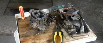
Repair instructions
As a rule, carburetor adjustment is required after 7500–8000 km. If the car is not used much, then this work should be carried out at least once a year. Before tuning, thoroughly clean the spark plugs, distributor and check the wiring.
List of tools and preparatory work
Adjustment does not require much physical strength, the main thing is to do everything accurately and accurately. Preparing the tool:
- set of wrenches;
- flat and Phillips screwdrivers;
- rags;
- latex gloves;
- toothpicks;
- solvent;
- pump or can of compressed air.
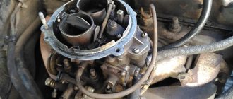
The first step is to remove the top cover, float and vacuum valve from the carburetor.
After unscrewing the 4 nuts, remove the top cover of the carburetor and clean the chambers
The internal chambers must be thoroughly cleaned of dust and soot residues. We clean small holes with air using a spray can or a regular pump. Warm up the engine and set it to the handbrake.
How to adjust: step-by-step instructions
- We tighten the two diffuser quality screws until they stop.
Screw 1 adjusts the amount of gasoline supplied, screw 2 adjusts the throttle position - Loosen the screws 2 turns and start the engine.
- Smoothly tighten the quality screw and the diffuser quantity screw. The first of them regulates the amount of fuel, and the second opens the throttle valve. Thus, we reduce the supply of fuel and air to the cylinders.
- We carry out a similar operation with each quality screw.
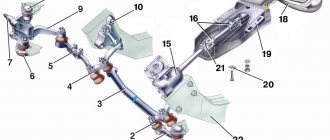
Carburetor control drive
The throttle valve opens from the pedal 9 (Fig. 36), which is mounted on the lever of the roller 12. The roller is mounted pivotally in two brackets 13, which are mounted on the front panel of the body. Levers are welded to the shaft and the action from lever 14 is transmitted to the longitudinal link 2, the intermediate link 15, the transverse link 1 and then to the throttle valve drive lever. Rods and 2 have plastic adjustable ends.
Rice. 36. Carburetor control drive:
1 - transverse thrust; 2 - longitudinal thrust; 3 — rod fastening bracket; 4 — air damper control cable; 5 and 7 - seals; 6 — cable handle; 8 — lock washer; 9 — throttle valve control pedal; 10 — return spring; 11 — lever; 12 - roller; 13 — bracket for mounting the roller; 14 — lever; 15 — intermediate lever; 16 — return spring fastening screw; 17 — return spring.
The air damper is controlled by button 6, which is connected by rod 4 to the air damper drive lever. The rod shell is mounted on the cover of the pneumatic drive of the secondary chamber throttle valve. When the button is fully extended, the air damper should be completely closed, and when it is recessed, it should be completely open.
Preparatory activities
If a motorist is interested in adjusting the Solex VAZ-2107 carburetor with his own hands, he must first carry out a number of preparatory steps.
Initially, you need to warm up the power unit to operating condition (temperature 85–90 degrees).
In the next step, you need to squeeze the handle of the air damper drive mechanism all the way; people simply call it “choke.” After this, the damper should be in a position in which the air channel is completely free, i.e., located in the direction of air movement.
If there is a tachometer, the device must be connected to the engine being turned off. Otherwise, if there is no unit, the item should be skipped. The positive side of the device should go to the ignition coil, and the negative side should go to the “ground” of the vehicle (body, engine or battery negative). Before connecting the device, you should read the operating instructions.
The last action should be to start the engine, turn on the high beam optics and the heating device.
Carburetors 2101-1107010 and 2101-1107010-02
They differ from 2105-1107010-20, as well as from each other in jet diameters. Carburetors with sequential throttle valves have a float chamber unbalance valve and a heated throttle body.
The float chamber unbalance valve makes it easier to start a hot engine by preventing fuel vapor from entering the engine inlet tract, which can lead to an excessively rich mixture and, therefore, difficult starting. When the throttle valves are closed, the float chamber is connected to the atmosphere through a valve. When the throttle valve is turned, the valve drive lever is released, and the valve, closing, separates the float chamber from the atmosphere.
What engines were the first VAZs equipped with?
“Kopeykas” were equipped with two types of power units: 2101 and . The design of the first was borrowed from the Italian Fiat 124. But this was not a copy, but a real improved version, although the camshaft was modernized. Unlike the Fiat, in which it was located at the bottom of the cylinder head, in the VAZ 2101 the shaft was located at the top. The working volume of this engine was 1.2 liters. It was capable of developing a power of 64 hp. s., which was plenty at that time.
The design of the “penny” engine was borrowed from Fiat
The VAZ 2101 engine differed from its predecessor in volume, which increased to 1.3 liters, and, accordingly, in the size of the cylinders. This did not lead to a significant improvement in power characteristics, however, it was this unit that became the prototype for subsequent modifications, namely 2103 and 2105.
The VAZ 2101 engine has four cylinders arranged in one row
Table: main characteristics of VAZ 2101 and VAZ 21011 engines
| Positions | Indicators | |
| VAZ 2101 | VAZ 21011 | |
| Type of fuel | Gasoline-76, AI-92 | Gasoline AI-93 |
| Injection device | Carburetor | |
| Cylinder block material | Cast iron | |
| Cylinder head material | Aluminium alloy | |
| Weight, kg | 114 | |
| Cylinder arrangement | Row | |
| Number of cylinders, pcs | 4 | |
| Piston diameter, mm | 76 | 79 |
| Amplitude of piston movement, mm | 66 | |
| Cylinder diameter, mm | 76 | 79 |
| Working volume, cm3 | 1198 | 1294 |
| Maximum power, l. With. | 64 | 69 |
| Torque, Nm | 87,3 | 94 |
| Compression ratio | 8,5 | 8,8 |
| Mixed fuel consumption, l | 9,2 | 9,5 |
| Declared engine life, thousand km. | 200000 | 125000 |
| Practical resource, thousand km. | 500000 | 200000 |
| Camshaft | ||
| location | top | |
| valve timing width, | 232 | |
| the value of the exhaust valve advance angle, | 42 | |
| intake valve lag, | 40 | |
| diameter of seals, mm | 56 and 40 | |
| width of seals, mm | 7 | |
| Crankshaft | ||
| Neck diameter, mm | 50,795 | |
| Number of bearings, pcs | 5 | |
| Flywheel | ||
| outer diameter, mm | 277,5 | |
| bore diameter, mm | 256,795 | |
| number of ring teeth, pcs | 129 | |
| weight, g | 620 | |
| Recommended Engine Oil | 5W30, 15W40 | 5W30, 5W40, 10W40, 15W40 |
| Engine oil volume, l | 3,75 | |
| Recommended Coolant | Antifreeze | |
| Coolant quantity, l | 9,75 | |
| Timing drive | Chain, double row | |
| Cylinder operating order | 1–3-4–2 |
Carburetor VAZ 2101
Diagram of the main metering system of the VAZ 2101 carburetor and econostat: The VAZ 2101 econostat is located in the secondary chamber of the carburetor. In the diagram it is conventionally shown in the primary chamber. 1 – Econostat emulsion jet; 2 – emulsion channel of the econostat; 3 – air jet of the main dosing system; 4 – econostat air jet; 5 – econostat fuel jet; 6 – needle valve; 7 – float axis; 8 – locking needle ball; 9 – float; 10 – float chamber; 11 – main fuel jet; 12 – emulsion well; 13 – emulsion tube; 14 – axis of the throttle valve of the primary chamber; 15 – spool groove; 16 – spool; 17 – large diffuser; 18 – small diffuser; 19 – sprayer.
Idle speed of the carburetor VAZ 2101
Diagram of the VAZ 2101 carburetor idle system: 1 – throttle body; 2 – throttle valve of the primary chamber; 3 – holes for transition modes; 4 – hole, adjustable with a screw; 5 – air supply channel; 6 – adjusting screw for the amount of mixture; 7 – adjusting screw for the composition (quality) of the mixture; 8 – emulsion channel of the idle system; 9 – additional air adjusting screw; 10 – carburetor body cover; 11 – air jet of the idle system; 12 – fuel jet of the idle system; 13 – fuel channel of the idle system; 14 – emulsion well.
Acceleration pump VAZ 2101
Diagram of the accelerator pump of the VAZ 2101 carburetor: 1 – screw valve; 2 – sprayer; 3 – fuel channel; 4 – bypass jet; 5 – float chamber; 6 – accelerator pump drive cam; 7 – drive lever; 8 – return spring; 9 – diaphragm cup; 10 – pump diaphragm; 11 – inlet ball valve; 12 – gasoline vapor chamber.
VAZ 2101 carburetor starting device
VAZ 2101 diagram of a diaphragm starting device: 1 – air damper drive lever; 2 – air damper; 3 – air pipe of the primary chamber of the carburetor; 4 – traction; 5 – starting rod; 6 – starting device diaphragm; 7 – adjusting screw of the starting device; 8 – cavity communicating with the throttle space; 9 – telescopic rod; 10 – damper control lever; 11 – lever; 12 – axis of the throttle valve of the primary chamber; 13 – lever on the axis of the primary chamber damper; 14 – lever; 15 – axis of the throttle valve of the secondary chamber; 16 – throttle valve of the secondary chamber; 17 – throttle body; 18 – throttle control lever of the secondary chamber; 19 – thrust; 20 – pneumatic drive.
Throttle valve of the second chamber of the VAZ 2101
Diagram of the pneumatic drive of the VAZ 2101 throttle valve of the secondary chamber: 1 – pneumatic drive nozzle located in the diffuser of the primary chamber; 2 – damper control lever; 3 – lever rigidly connected to the axis of the throttle valve of the primary chamber; 4 – lever that limits the opening of the throttle valve of the secondary chamber; 5 – pneumatic drive nozzle located in the diffuser of the secondary chamber; 6 – lever connected to lever 9 through a spring; 7 – axis of the throttle valve of the secondary chamber; 8 – pneumatic drive rod; 9 – throttle control lever of the secondary chamber; 10 – channel for supplying vacuum to the pneumatic drive; 11 – rod bushing; 12 – pneumatic drive of the throttle valve of the secondary chamber.
Carburetor VAZ2101, carburetor deviceCarburetor of engines 2101 and 21011. VAZ cars are equipped with a two-chamber vertical carburetor (Fig. 82) with sequential opening of the throttles. The secondary chamber throttle is driven mechanically and is carried out by a system of levers from the primary chamber throttle.
The carburetor is equipped with an automatic starter, a diaphragm accelerator pump and a float chamber unbalance valve. A spool valve for the engine crankcase ventilation system is installed on the throttle axis of the primary chamber; The throttle body in the area of the idle channels is heated by the engine cooling system.
Rice. 82. Carburetor: a - view of the carburetor body with the cover removed; 1 — screw for adjusting the mixture composition; 2 — idle jet housing; 3 - main air jets; 4 — accelerator pump valve plug; 5 — main jets; 6 — accelerator pump spray valve; 7 — air jets of the idle system; b - view of the carburetor body cover; 1 — valve for unbalancing the float chamber; 2 — fuel supply pipe to the carburetor; 3 — carburetor fuel filter cover; 4 - float; 5 — econostat fuel jet; 6 — econostat emulsion jet; 7 - air damper
Rice. 83. Main dosing system, econostat, spool device: 1 - emulsion jet of econostat; 2 — emulsion channel of the econostat; 3 — air jet of the main dosing system; 4 — econostat air jet; 5 - econostat fuel jet; 6 — needle valve; 7 — float axis; c — needle valve ball; 9 — float; 10 - float chamber; 11 - main jet; 12 - emulsion well; 13 - emulsion tube; 14 — throttle axis of the primary chamber; 15 — spool groove; 16 — spool; 17 — large diffuser; 18 — small diffuser; 19 — sprayer; 20 — crankcase gas inflow tube; 21 - calibrated hole
In 1974, carburetors 2101-110701.0-02 began to be used on cars. reducing the content of carbon monoxide in engine exhaust gases. These carburetors differ from the usual 2101-1107010 in the diameters of the jets (Table 4). On the BA3-2103 car, a carburetor with a block valve is installed to shut off the idle channels when the ignition is turned off and has a modified calibration. Therefore it will be discussed below.
Main dosing system. Fuel enters float chamber 10 through needle valve 6 (Fig. 83); float 9 installed on axis 7 maintains the required fuel level. From the float chamber, fuel through the main jets 11 enters the emulsion well 12, mixes with the air coming out of the holes of the emulsion tubes 13 and entering them through the air jets 3. Then, through the nozzles 19, the fuel enters the small 18 and large carburetor diffusers.
The main air jets of the 3 primary and secondary chambers are identical in appearance. They are distinguished by the marking stamped on the upper plane of the nozzle head (for example, 170 or 190), which indicates the diameter of the nozzle hole (1.70 or 1.90 mm).
For main fuel jets 11, markings are applied on the side surface of the head (135 or 125) and also indicate the diameter of the nozzle opening (1.35 or 1.25 mm).
The emulsion tubes of the 13 primary and secondary chambers of the VAZ-2101 carburetor are the same. However, they may be different on other car models. Therefore, a marking (for example, 15) is applied to the cylindrical surface at the bottom of the tubes, which indicates the calibration number of the tube. Small diffusers 18 also have markings (for example, 4 or 4.5), indicating the calibration number of the atomizer hole 19.
Enrichment device (econostat). The carburetor has an enrichment device included in the secondary chamber. Fuel from the float chamber through fuel nozzle 5 enters the econostat channels located in the carburetor body cover, where it is mixed with air entering through nozzle 4. The fuel-air emulsion through channel 2 passes through the calibrated hole of the nozzle /, enters the small channel of the atomizer and diffuser 18. The econostat comes into operation at speeds close to maximum with the throttles fully open.
The spool valve for crankcase ventilation includes a spool 16, sitting on the axis 14 of the primary chamber throttle. Tube 20 is connected to the engine crankcase ventilation system and can communicate with a cavity open to the throttle space. The operation of the device is described in the section <Engine crankcase ventilation system>.
The throttle drive (Fig. 84) works as follows. When the drive rod of the throttle control pedal (not shown in the diagram) acts on the ball pin of lever 11, the lever, rigidly sitting on the throttle axis of the primary chamber, rotates counterclockwise, the throttle begins to open. Sector 13, rigidly sitting on the axis, also rotates, while its protrusion 12, rotating along with the axis, passes through a certain area until it rests against the intermediate lever 16, the pin of which fits into the groove of the lever 1'91 sitting on the Throttle axis secondary camera. With further rotation of the throttle axis of the primary chamber, the protrusion 12 turns the lever 16, which, in turn, through the lever 19 begins to open the throttle of the secondary chamber. The arm ratios of the three levers are selected so that the secondary chamber throttle opens after the primary chamber throttle rotates through an angle of 48°. The throttles reach the full open position simultaneously.
The starting device is used to start a cold Engine. When the trigger button (located under the instrument panel) is pulled out, the three-arm lever 1, rotating around its axis, takes position A, while simultaneously opening the throttle of the primary chamber using rod 22 and lever 21.
Rice. 84. Starting device and throttle drive: 1 - choke control lever; 2 — air damper of the starting device; 3 — air pipe of the primary chamber of the carburetor; 4 - traction; 5 - rod; 6 - diaphragm; 7 — adjusting screw of the starting device; 8 - cavity communicating with the throttle space; 9 — telescopic rod; 10 — adjusting screw of the throttle of the primary chamber; 11 — throttle control lever; 12 - protrusion; 13 - sector; 14 — throttle axis of the primary chamber; 15 — primary chamber throttle; 16 — intermediate lever for the throttle drive of the secondary chamber; 17 — throttle axis of the secondary chamber; 18 — secondary chamber throttle; 19 and 21 — levers; 20 — protrusion of the intermediate lever; 22 - rod connecting the primary chamber throttle with the starting device drive; 23 — return spring of the throttle drive lever of the secondary chamber; 24 — bolt for fastening the starter drive cable; 25 — starting device diaphragm housing; 26 — air damper control lever; 27 — ball pin of the throttle drive lever of the primary chamber; 28 — screw for adjusting the throttle position of the secondary chamber; A - position of lever 1 at start-up; B - position of lever 1 during engine operation
Telescopic rod 9 acts on a lever that sits motionless on the axis of the air damper. The air damper 2 closes, and the end of the rod 4, moving in the groove of the rod 5, occupies the extreme left position. During the first flares and subsequent operation of the engine at idle, the vacuum from the throttle space is transferred to cavity 8. Diaphragm 6, acting through rod 5 on rod 4 and lever, slightly opens the air damper. Limits for opening the air damper, ensuring that the mixture entering the engine is not excessively rich or lean engine are adjusted by bending rod 4 and rotating adjusting screw 7.
When starting a cold engine, turn on the starting device fully by pulling the control button all the way. The throttle pedal must not be pressed even if the engine does not start. This will prevent fuel overflow.
After starting, when the engine warms up, gradually turn off the starting device, ensuring stable operation of the engine, and when the engine is completely warmed up, turn off the starting device by returning the control button to its original position, while lever 1 is in position B; the air damper opens completely.
Rice. 85. Idle system and float chamber unbalance valve: a - diagram; b - view of the carburetor from the side of the float chamber unbalance valve; 1 - channel connecting the float chamber with the atmosphere; 2 - valve; 3 - float chamber; 4 - rod; 5 — intermediate lever; b — carburetor body; 7-secondary mixing chamber; 8 — secondary chamber throttle; 9 - primary chamber throttle; 10) - accelerator pump drive lever with stop A; 11 - primary mixing chamber; 12 - hole. screw adjustable; 13- holes for transition modes; 14 — adjusting screw; 15 — heating channel for the throttle body; 16 - emulsion well; 17 — emulsion channel of the idle system; 18 — fuel channel of the idle system; 19 — fuel jet of the idle system; 20 — air jet of the idle system; A - emphasis; B - spring of the intermediate lever of the unbalance valve drive
The idle system (Fig. 85) is switched on behind the main jet. Fuel from the emulsion well 16 through channel 18 enters the idle jet 19, mixes with air entering through the air jet 20, and through channel 17 enters hole 12, open to the throttle space. The flow area of the hole is adjusted by screw 14. The arrangement of holes 13 ensures that there are no failures in engine operation when the throttle is opened.
The secondary chamber includes a system that differs from the idle system of the primary chamber in the absence of an adjusting screw 14 and hole 12. This system ensures that there are no failures in engine operation when the throttle of the secondary chamber is opened and is called a transition system. The transition system is included directly in the float chamber.
On the cylindrical belt of the fuel nozzles 19 there is a marking (for example, 45 or 60), indicating the diameter of the holes of the fuel nozzles (0.45 or 0.60 mm).
Float chamber unbalance valve. At the throttle positions of the primary chamber corresponding to low idle speeds, lever 10 of the accelerator pump drive with stop A (see Fig. 85, a) holds back the spring-loaded Lever 5. Valve 2, pressed by the spring to rod 4, is in the lowest position, and float chamber 3 communicates with the atmosphere through channel 1. When the throttle is turned in the Open direction, stop A releases lever 5, which rotates under the action of spring B (counterclockwise) and, acting through the rod on the valve, closes it. In this case, the float chamber is disconnected from the atmosphere.
The valve serves to facilitate starting a hot engine by preventing fuel vapor from entering the engine inlet tract, which can lead to an excessively rich mixture and, therefore, difficult starting.
Heating of the throttle body. To prevent ice from forming on the carburetor elements located in the area of the throttle gap of the primary chamber valve during the cold season, the carburetor is equipped with heating for the idle channel area from the engine cooling system. The inlet 16 and outlet 18 are shown in Fig. 86, b.
Accelerator pump (Fig. 86). When the throttle of the primary chamber is opened, lever 6, sitting on its axis, rotates and through lever 7 acts on the spring-loaded end of cup 9. Diaphragm 10, overcoming the force of return spring 8, pushes fuel from cavity A into channel 3, ball valve-screw / and through sprayer 2 - into the diffuser of the primary chamber of the carburetor. Valve 11 closes.
The sprayer 2 has a marking (for example, 40) indicating the diameter of the sprayer hole (0.40 mm).
Bypass jet 4 is selected in such a way that when the diaphragm moves sharply, the required mode is ensured
Rice. 86. Accelerator pump: a - diagram; b - view of the carburetor from the side of the accelerator pump; 1 — ball valve-screw; 2- accelerator pump nozzle; 3 - fuel channel; 4 - bypass jet; 5 - float chamber; 6 and 7 - accelerator pump drive levers; 8-return pump spring; 9 — diaphragm cup; 10 — pump diaphragm; 11 — inlet ball valve; 12 — pump vapor chamber; 13 — housing of the fuel jet of the idle system; 14 — body of the emulsion jet of the idle system; 15 — accelerator pump cover; 16 — inlet pipe for heating the throttle body; 17 — screw for adjusting the mixture composition at engine idle speed; 18 — outlet pipe for heating the throttle body; 19 — screw that regulates the opening of the primary chamber throttle; 20 - pipe for supplying crankcase gases to the spool device
engine operation, and when the diaphragm moves smoothly or oscillates on a rough road, all the fuel displaced by the diaphragm enters the float chamber without disturbing the required engine operating mode.
The profile of lever 6 is designed so that the pump performs double fuel injection, with the second injection coinciding with the moment the secondary chamber throttle opens
Carburetor control drive. The carburetor throttle control drive is lever driven, and the air damper control drive is cable driven. The throttles are driven by pedal 9 (Fig. 87), hinged on the floor of the cabin. The pedal, through the sleeve 8, acts on a lever welded to the roller 12. The roller rotates in two plastic brackets 13, attached to the front panel of the car.
Two more levers are welded to the shaft - 11 and 14. A spring 10 is attached to lever 11, and lever 14 is connected to lever 11 (see Fig. 84) of the throttle drive through longitudinal rod 2, lever 15 and transverse rod 1.
A screw 16 is screwed into the intake pipe (see Fig. 87), to which a spring 17 clings. Lever 15 rotates on an axis welded to the cylinder head cover. Rods 1 and 2 have plastic threaded ends.
When pedal 9 is fully depressed, the throttles should be fully open and the throttle levers should not have additional travel. If this is not the case, then the position of the pedal and throttles can be coordinated by changing the length of rod 2 by unscrewing or screwing in its tip.
Rice. 87. Carburetor control drive: 1 - transverse rod: 2 - longitudinal rod; 3 — rod fastening bracket; 4- air damper control cable; 5 and 7 - seals; 6 — air damper control cable handle 8 — bushing; 9 — throttle control pedal; 10 — return spring; 11 and 14 — return spring fastening screw: 13 — roller fastening bracket; 15 — intermediate lever; 16 — fastenings of the return spring; 17 - return spring
The air damper is controlled by a cable 4, the handle 6 of which is located under the instrument panel. The cable sheath is attached to the carburetor with bolt 24 (see Fig. 84, b), and the end of the cable is attached to the choke control lever 26.
The cable and its sheath must be secured so that when handle 6 is fully extended (see Fig. 87), the air damper is completely closed, and when the handle is recessed, it is completely open.
Read more about VAZ cars...
Carburetor VAZ 2101: design and repair
From time to time, owners of carburetor Zhigulis are puzzled by uneven engine operation at idle, failures during acceleration and poor starting. One of the reasons for these problems is a malfunction of the fuel system, in particular the carburetor.
Classification
Carburetor for VAZ 2101
A large number of classic Zhiguli models use the VAZ 2101 carburetor in various modifications. There are several modifications of manufactured carburetors, which differ not only in the size of the installed jets, but also in the presence or absence of a vacuum corrector system.
The VAZ 2101 carburetor of all modifications is intended only for VAZ 2101 and 21011 engines, where an ignition distributor without a vacuum corrector is installed. On cars of later production systems are installed that are already equipped with vacuum correctors. It should be remembered that the use of carburetors for VAZ 2101, 21011 and 2105 engines without a vacuum regulator cannot be used on other engines and vice versa. The carburetor of the VAZ 2103 and VAZ 2016 is used in a similar way - only on models where there is no vacuum corrector.
Maintenance and adjustment of carburetors at home is a rather complex procedure that requires certain skills, knowledge and tools. You can independently adjust the idle speed, replace gaskets, clean jets, fuel channels, and also visually check the operation of the accelerator pump and, if necessary, replace it. But it is advisable to carry out final adjustments and adjustments in a car service center that has diagnostic equipment for checking the level of carbon monoxide in the exhaust gases.
Carburetor design, diagnostics, adjustment
Carburetor body diagram for VAZ 2101
The design of carburetors is fundamentally little different and consists of the following systems:
- Fuel level maintenance and adjustment system;
- Engine starting and warming system;
- Idle system;
- Acceleration pump;
- Main dosing system;
- Econostat systems.
Fuel level system
The fuel level is controlled by a float in the carburetor float chamber. Both excess and insufficient fuel levels will negatively affect engine performance. This problem occurs mainly due to a leak in the fuel valve, which occurs quite often due to poor quality fuel with fuel filters. Cleaning the valve or replacing it if there is no tightness is carried out after visual inspection, being a fairly simple operation.
Starting and idle system
Carburetor for VAZ 2101 used
The starting and idle systems are the most vulnerable mechanisms. Poor engine starting is often caused by incomplete closing of the air damper. It can be eliminated by cleaning its drive with lubricant. In addition, it is necessary to check how it opens slightly at the moment of starting, which is ensured by the starting mechanism.
If the idle speed is unstable, you must first check the electric idle air valve by applying voltage to it. The absence of clicks will immediately indicate a defect, which will require replacement of the unit. It is also possible for dirt to get into its channel. It is necessary to clean the valve jet, then clean the channel.
Idle speed adjustment is carried out as follows. First, you need to achieve the required engine speed with the screw for the amount of fuel mixture (for VAZ engines this figure is 850 rpm). Then, using the quality screw, you need to find a position at which the engine will develop the highest speed. If its speed is more than 850 rpm, then you need to reduce it with the quantity screw, and then achieve maximum speed with the quality screw. After the speed is set to 850 rpm, you need to tighten the quality screw until the engine begins to shake slightly. Then turn the quality screw back about a third or a quarter of a turn, achieving the most stable operation of the engine at the leanest mixture.
Acceleration pump
Another common problem is a malfunctioning accelerator pump, which results in dull or jerky acceleration. The defect is checked visually. You need to sharply open the throttle, checking the presence and strength of the gasoline stream, which should be uniform for 3-4 seconds. If this is not the case, then it is necessary to check the valve retraction or clean the nozzle.
Perhaps these are the most common simple malfunctions and methods for eliminating them. If you cannot resolve them on your own, it is recommended to contact a professional service.
Signs of a carburetor malfunction
The VAZ 2101 carburetor is a device that requires periodic cleaning and adjustment, which is determined by operating conditions and the fuel used. If problems arise with the mechanism in question, signs of problems will be reflected in the operation of the power unit: it may twitch, stall, gain speed poorly, etc. As the owner of a car with a carburetor engine, it will be useful to understand the main nuances that can arise with the carburetor. Let's look at the signs of malfunctions and their causes.
Stalls at idle
A fairly common problem on a penny car is a stalling engine at idle. The most likely reasons are:
- clogging of jets and XX channels;
- failure or incomplete closing of the solenoid valve;
- malfunction of the EPHH unit (forced idle economizer);
- Damage to the quality screw seal.
The carburetor is designed in such a way that the first chamber is combined with the XX system. Therefore, if the engine operates problematically in idle mode, not only failures can be observed, but also a complete stop of the engine when the vehicle begins to move. The problem can be solved quite simply: faulty parts are replaced or the channels are washed and purged, which will require partial disassembly of the unit.
Video: restoring idle speed using the example of a Solex carburetor
Dips during acceleration
Sometimes when accelerating a car, so-called dips occur. A failure is when, after pressing the gas pedal, the power plant operates at the same speed for several seconds and only then begins to spin up. Dips are different and can lead not only to a later response of the engine to pressing the gas pedal, but also to its complete stop. The cause of this phenomenon may be a clogged main fuel jet. When the engine operates with light loads or at idle, it consumes a small amount of fuel. When you press the accelerator pedal, the engine switches to higher load modes and fuel consumption increases sharply. If the fuel nozzle becomes clogged, the flow area becomes insufficient, which leads to failures in the operation of the power unit. The problem is eliminated by cleaning the nozzle.
Dips, as well as jerks, can be associated with a loose fit of the fuel pump valves or with clogging of the filter elements, i.e., everything that can create resistance when supplying fuel. In addition, air may leak into the power system. If the filter elements can be simply replaced, the carburetor filter (mesh) can be cleaned, then the fuel pump will have to be dealt with more seriously: disassembled, troubleshooting, installing a repair kit, and possibly replacing the unit.
If dips are observed during acceleration, it is necessary to clean the carburetor strainer.
Pouring candles
One of the problems that can happen with a carburetor engine is when the spark plugs flood. In this case, the spark plugs become wet from a large amount of fuel, and a spark becomes impossible. As a result, starting the engine will be problematic. If you unscrew the spark plugs from the spark plug well at this moment, you can make sure that they will be wet. This problem in most cases is associated with the enrichment of the fuel mixture at the time of start-up.
Candles can flood for a number of reasons:
- The carburetor starter does not work;
- the needle valve has failed;
- pumps the fuel pump;
- air jets clogged.
Let's look at each of the reasons in a little more detail. In most cases, the problem of flooded spark plugs on the VAZ 2101 and other “classics” occurs during a cold start. First of all, the starting gaps on the carburetor must be correctly set, i.e., the distance between the dampers and the walls of the chamber. In addition, the diaphragm of the starter must be intact and its housing must be sealed. Otherwise, when starting the power unit cold, the carburetor air damper will not be able to open slightly to the desired angle, which is the purpose of the starting device. As a result, the combustible mixture will be forced to be depleted of air supply, and the absence of a small gap will contribute to the formation of a richer mixture, which will lead to the effect of “wet spark plugs”.
As for the needle valve, it may simply be leaking, resulting in excess fuel leaking into the float chamber. This situation will also lead to the formation of a rich mixture at the moment of starting the power unit. If there is a malfunction with the needle valve, the spark plugs can be filled either cold or hot. In this case, it is best to replace the part.
Spark plugs can flood for various reasons, as a result of which starting the engine becomes problematic.
The spark plugs can also flood due to improper adjustment of the fuel pump drive, as a result of which the pump pumps fuel. In this situation, excess gasoline pressure is created on the needle-type valve, which leads to fuel overflow and an increase in its level in the float chamber. As a result, the fuel mixture becomes too rich. In order for the rod to protrude to the required size, it is necessary to install the crankshaft in a position in which the drive will protrude minimally. Then measure d, which should be 0.8–1.3 mm. The desired parameter can be achieved by installing gaskets of different thicknesses (A and B) under the fuel pump.
To prevent the fuel pump from pumping fuel, it is necessary to adjust the rod (drive)
The air jets of the main metering chamber are responsible for supplying air to the fuel mixture: they create the required proportion of gasoline and air, which is necessary for normal engine starting. If the jets are clogged, the air supply is partially or completely stopped. As a result, the fuel mixture becomes over-enriched, which leads to flooding of the spark plugs. The problem is solved by cleaning the jets.
Smell of gasoline in the cabin
Sometimes VAZ 2101 owners are faced with the problem of the presence of the smell of gasoline in the cabin. The situation is not the most pleasant and requires a quick search for the cause and its elimination. After all, fuel vapors are not only harmful to health, but also dangerous in general. One of the reasons for the appearance of the smell may be the gas tank itself, i.e. a microcrack could appear in the container. In this case, you will need to find the leak and seal the hole.
One of the reasons for the smell of gasoline in the cabin is damage to the fuel tank.
In addition to the fuel tank, the fuel line itself can become leaky, especially if we are talking about a “penny” car, because the car is far from new. Fuel hoses and pipes need to be checked. In addition, attention should be paid to the fuel pump: if the membrane is damaged, the mechanism may leak and the smell may penetrate into the cabin. Since the carburetor supplies fuel mechanically, the device must be adjusted over time. If this procedure is carried out incorrectly, the carburetor may overflow fuel, which will lead to a characteristic odor in the cabin.
Checking the pump accelerator and repairing it
You need to start checking by testing the functionality of the system. You need to collect in a beaker the fuel that will be generated during 10 cycles of operation of the throttle lever. From 5.2 to 8.7 cm³ of fuel should accumulate. If this is not the case, you need to clean the VAZ 2101 carburetor jets. To do this, bleed the pump. This will help clear clogged injectors. This procedure is performed about 10 times. Then the fuel is measured again.
If the purging procedure does not give the desired result, the accelerator will need to be completely replaced.
If the engine malfunctions at high speeds, you need to check the pump diaphragm. It could wear out. The fuel pump rod often wears out.
Single chamber weber carburetor
Single chamber Weber carburetor or SURPRISES OF A LONELY CHAMBER
Is a single-chamber Weber carburetor capable of replacing the domestic DAAZ?
Which device causes the most trouble to the owner of a domestic car? Of course, the carburetor. the vagaries of Solex and Ozone carburetors , and their repair is still one of the most pressing topics in garage disputes and conversations in the smoking room. Is it possible to end the torment in one fell swoop, so as to forget once and for all about purging channels, forced idle valves, jerks and failures?
Unfortunately, in our country, fuel injection systems will not completely replace carburetors any time soon. But now it is possible to replace a domestic device with an imported one - Weber carburetors for VAZ cars have appeared in spare parts stores. And not the beloved two-chamber model that was installed on the first Lada cars. The current Weber-32ICE/55T 251 is a simple single-chamber carburetor with a falling flow without any complex additional systems. Two modifications go on sale: for “classics” and for front-wheel drive Samaras. They differ from each other only in a set of adapter parts for installation, made in Italy. Well, let's compare the primitive-looking Weber with the most modern domestic carburetor DAAZ-21083, which is produced under license. THEY ARE GOING TO THE START.
Three carburetors took part in the comparison test. "Weber-32ICE" is provided by the supplier company - "Italian Trade Organization". At the warehouse, we took the first box with a carburetor we came across. Before testing began, the device was not opened or adjusted. Since the high quality of the product is guaranteed, there is nothing to control the compliance of a specific sample with factory data. From the accompanying documentation it follows that Weber received a certificate of conformity from Gosstandart and complies with UNECE standards No. 83 and GOST 17.2.2.03-87. In addition, the device meets the German TÜV requirements, and the toxicity does not exceed the permissible limit for vehicles using leaded gasoline.
The standard DAAZ-21083 was removed from a new car (mileage 200 km). We didn’t risk buying the device from a spare parts store - there are too many outright defects there. Before the test, we removed the cover, checked the fuel level in the float chamber, the correspondence of the jets to the nominal value, and the operability of most systems. The Russian Solex must also be in good working order and adjusted to factory specifications - this is the requirement for the purity of the experiment. The third participant in the test is the same DAAZ, but with changed adjustments (they are most often used by craftsmen to improve the driving characteristics of the car). Instead of the air jet of the first chamber marked “165”, “155” was installed, and the fuel jet of the second chamber “97.5” was replaced with “100”. Both non-standard jets are factory ones - they are used in the 21083-31 carburetor with an automatic starter. In addition, the accelerator pump nozzle was replaced with a Nivovsky one (from a DAAZ-21073 carburetor) - with a nozzle directed only into the first chamber. You will find the main parameters of all three devices in the table. 1.
The “carrier” of the experimental carburetors was a completely serviceable VAZ 21093 car with a 1500 cm3 engine, a 3.9 main pair and Barum OR-42 tires with a size of 175/70R13. With a tire pressure of 2 kgf/cm2, the run-out of the “nine” from a speed of 50 km/h was 576 m. Driving tests took place on special roads at the NITSIAMT test site using the professional Datron measuring complex for measurements. Movement in a conventional urban cycle was simulated in the laboratory on running drums. WHAT THE NUMBERS SAID First, let's look at the results of laboratory studies (Table 2). No miracles happened with fuel consumption in the conventional urban cycle. The most economical is the standard Solex, the modified one is slightly behind, the outsider is the single-chamber Weber. But there is one caveat. All three carburetors were “run in” using the same method, without taking into account the features of each device - this is how comparative tests are carried out. But in the hustle and bustle of the city, consumption greatly depends on driving style, the ability to use the advantages of a particular carburetor and a host of external factors. This means that you can get different numbers and the picture will change. Although, of course, due to its design features, “Weber” still won’t make it to the top. As for the toxicity of exhaust gases, formally all devices met the requirements of GOST and UNECE. Moreover, most indicators do not differ much. But the Weber’s CO content at high speeds is at its limit, while both Solexes have a substantial reserve. What's the matter? Additional research showed that not all Italian carburetors tend to “smoke” so much. We managed to get to the bottom of the reason (the tolerances in the manufacture of jets are large) and gave the supplier the appropriate recommendations. Road tests, during which the car's acceleration dynamics, engine elasticity (Table 3) and fuel efficiency (Fig. 1) were assessed, were downright a triumph for the modified Solex: it was ahead of its competitors in almost all respects. But let us remember that, compared to the standard DAAZ-21083, the converted one consumes more fuel in the conventional urban cycle, and is also, at least slightly, still inferior in terms of exhaust toxicity. There are other “buts”, which will be discussed below. In the meantime, let's compare the regular DAAZ with the Weber. The maximum speed is higher with a domestic carburetor. When accelerating from zero to 100 km/h with a difference of more than a second, the Solex wins again. But take a look at the acceleration curves (Figure 2). Up to a speed of 80 km/h, the carburetors, as they say, go neck and neck, and only then the Weber begins to lag noticeably behind. There's nothing to be done - he really misses it. second camera. What about elasticity? With the standard test method in IV and V gears, the picture is repeated. At first, Weber keeps pace with DAAZ, then lags behind. Now let’s complicate the task: acceleration in the same gears, but from a minimum speed, when the speed is below 1000 rpm and the car is moving “pull” (Fig. 3 and 4). What a trick! “Weber”, it turns out, has excellent “lower end” - the engine with it has a lot of torque. In fourth gear, the Solex is ahead until the car reaches 100, and in fifth - 120 km/h. Then the DAAZ takes its toll - at high speeds the two-chamber is noticeably more lively. During this exercise, the “Italian” received flattering evaluations from experts. When we tried to accelerate at low speed with the Solex, the car jerked every now and then, but with the Weber it pulled surprisingly smoothly. Now let's look at the fuel-speed characteristics (see Fig. 1). Using them, you can estimate gasoline consumption when driving in fifth gear at a steady speed. In its very driving range - from 65 to 105 km/h - the Weber is more economical than the DAAZ, and from 80 to 100 km/h it is barely inferior to the modified Solex. And this property of the “Italian” must be used. Do Samara owners often engage fifth gear when they barely reach 70 km/h? Of course not: the car can barely pull and even a gentle hill will require you to switch to a lower gear. And “Weber” behaves well in such a situation and even allows you to accelerate without switching. LET'S TURN AWAY FROM INSTRUMENTS Carburetors have passed a whole range of tests. The car drove in a circle with a diameter of 25 m at speeds of 20, 30, 40 and 50 km/h, overcame cascades of turns of varying steepness on the mountain road of the test site, climbed 30- and 40-percent slopes and descended from them, stopped in the middle of the slide and worked at idle, rolled downhill for a long time at forced idle with the gear engaged, but the gas pedal fully released. All three devices passed the tests perfectly - there were no malfunctions. Even the Weber, which, unlike the Solex, does not have twin floats immersed in narrow wells, was not, contrary to expectations, bothered by the ebb or flow of gasoline in the float chamber.