The high power and efficiency of modern combustion engines is due to the use of electronic devices that control the fuel injection process. The Lada Priora camshaft sensor is one of such elements.
This product allows you to determine the exact position of the gas distribution mechanism in relation to the crankshaft.
Meter design and location
The operating principle of the DPRV is based on the Hall effect - the sensor reacts to the approach of a metal mass by changing the voltage on the signal wire. The design of the device is similar to another element - the crankshaft position detector. Inside the plastic case there is a coil where the 12 V on-board voltage is constantly supplied.
The meter is installed on the engine cylinder head in close proximity to the camshaft. The latter is equipped with a special plate or gear, whose rotation affects the DPRV. The work algorithm looks like this:
- After turning on the ignition and starting the engine, a supply voltage of 12 V is supplied to the sensor. Through the third signal wire, the element supplies the controller with a voltage of 90–95% of the original one.
- When the protrusion on the rotating part of the camshaft passes next to the DPRV housing, the voltage at the signal contact drops to 0.2–0.4 volts, depending on the design of the device and the vehicle model.
- When the voltage drops, the electronic unit clearly “sees” the valve timing, promptly supplies the fuel mixture to the engine cylinders and directs the spark discharge to the desired spark plug.
Note. On cars with 16-valve engines, 2 sensors are installed - one for each camshaft.
When the meter is faulty, the electronics are unable to control the operation of the gas distribution mechanism. In such cases, the control unit goes into error and is guided by the signals of other meters. Spark generation and fuel supply are adjusted according to the programmed program, which affects the operation of the power unit.
Removing the sensor in three steps
To remove the phase sensor, first turn off the ignition. The sensor connector is easily disconnected - it is held in place by a plastic tab.
Sensor location and mounting
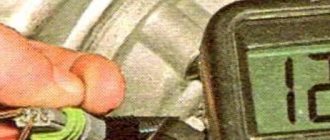
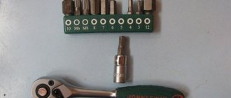
When the connector is disconnected, use a 10mm socket wrench to unscrew the two bolts holding the sensor in place (see photo). Then the sensor housing is removed from under the casing, pressing it against the cylinder head.
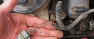
Here we show how the sensor is removed on the 21120 (16v 1.5) engine. For the VAZ-21124 engine, all steps will be the same. If you look at the car connector, you can see three terminals. Their purpose is explained in the drawing.
This is the sensor housing, not the vehicle terminal block
There is a desire to measure the voltage between the two terminals on the right. If you don't turn on the ignition, you'll be fine.
Characteristic symptoms of the problem
Practice shows that a malfunction of the camshaft position sensor does not lead to engine failure and immobilization of the vehicle. The engine continues to operate with some deviations that interfere with the normal operation of the car. Symptoms of DPRV failure are quite vague and similar to problems with other measuring elements:
- Unstable engine operation at idle and while driving.
- Instead of dynamic acceleration, after pressing the gas pedal, there is a series of small jerks and a sluggish increase in speed.
- The power of the power unit decreases. The effect becomes noticeable when the load increases - on a hill, sharp acceleration, while towing a trailer.
- The Check Engine light on the dashboard does not always come on. But many drivers note that if the meter is faulty, the display flashes after the crankshaft speed increases to 3000 rpm or more.
- Fuel consumption is naturally increasing.
If the measuring element is faulty, the control unit prepares and supplies an enriched air-fuel mixture to the cylinders. This results in an increase in gasoline consumption and unstable idling. Jerks and drops in power are caused by untimely supply of a spark - the controller “does not see” the end of the compression stroke in the cylinder and cannot clearly determine the ignition timing.
On various car models, additional symptoms of a malfunctioning camshaft sensor are noted:
- the engine suddenly stalls while driving, but starts without problems;
- cold starting of the engine becomes difficult;
- on cars equipped with a robotic gearbox, difficulties arise with automatic gear shifting;
- the engine “troits” - skipping ignition cycles is heard, sometimes popping sounds are observed in the exhaust manifold;
- On some cars, the power plant fails due to lack of sparking.
Reference. The service life of the element is quite long. On domestically produced cars, the resource reaches 80–100 thousand km, on imported cars – 150 thousand km. When searching for the causes of a malfunction, you can focus on the specified periods.
Driving with a broken air pressure sensor is acceptable for a short period. Jerking, rich fuel mixture and electronic errors accelerate the wear of spark plugs and engine parts. After detecting the listed symptoms, you should send the car for diagnostics or find the source of the problem yourself.
Subsequence
When you arrive at your destination, do not rush to turn off the engine while the air conditioning is running. This will place a greater load on the electrical power conversion system. First you need to turn off the air conditioner while the engine is running. You can do this by approaching your final route in advance. Since the air in your cabin is already cooled, turning off the cooling will not heat up the cabin in a short time. Also, turning off the air conditioner in advance will save you from the formation of a puddle under the car, which is formed as a result of condensation. At first glance there is nothing wrong with this. But it's not quite that simple. Condensation forms on the cooler in the cabin. The coolant passing through it lowers the temperature of the evaporator to very low values. The external hot air meets the cold fixative, resulting in the formation of water droplets. By turning off the air conditioning in advance while the car is moving, you will prevent the formation of harmful microorganisms due to moisture in the air conditioning system.
How to make sure the DPRV is working?
The easiest way to check the camshaft sensor is to connect a car scanner or a computer with an installed program corresponding to the make of the car to the diagnostic connector of the car. If the element is faulty, then after starting the engine the device will display the following error codes:
- P0340 – there is no signal from the camshaft position detector;
- P0341 – valve timing does not coincide with the compression/intake strokes of the cylinder-piston group;
- P0342 – the signal level in the electrical circuit of the DPRV is too low;
- P0343 – the signal level from the meter exceeds the norm;
- P0339 – an intermittent signal is received from the sensor.
Since the vast majority of car enthusiasts do not have scanners and laptops with software at their disposal, a more affordable method is practiced - checking with a digital multimeter. Diagnostics is carried out in 3 stages:
- Visual inspection of the wiring and continuity of the circuit for breaks.
- Measuring the outgoing current at the control contact of the DPRV.
- Testing functionality by approaching a metal object.
At the first stage, you need to ensure the integrity of the wiring and reliable contact of the connecting block. Carefully inspect the supply cables for kinks, cracks and melted insulation. Testing the current-carrying conductors and searching for a break is performed with the same multimeter. Don't forget to clean the connector contacts from oxidation.
After checking the electrical wiring, proceed to diagnosing the camshaft sensor itself. Instead of standard alligator clips on the tester, you need to use wires with needles so that you don’t have to be tricky with connecting to the connecting block. Diagnostic work is carried out in the following order:
- Open the hood and look for the DPRV on the cylinder head. Usually the element is placed on the end of the engine or the side wall of the cylinder head next to it.
- Using the vehicle's electrical diagram or data for a specific sensor model, determine the location of the two power contacts and the third wire going to the controller.
- Turn on the ignition and measure the voltage between the vehicle ground and the control contact of the element (on VAZ cars this is the middle wire, marked “C”). Normal multimeter readings are at least 90% of the supply voltage, that is, 12 * 0.9 = 10.8 V.
- If the obtained values are below normal, the sensor is faulty and must be replaced. Otherwise, perform the third stage of verification.
For final diagnostics, the part will have to be removed from the engine. Typically, the element is inserted into a hole in the cylinder head and secured with one bolt. Unscrew it, remove the DPRV and wipe off the engine oil. Do not disconnect the block with wires.
After connecting the multimeter to the middle contact and ground of the car, turn on the ignition again. Bring a steel object (for example, an open-end wrench) close to the end of the element, monitoring the display readings. A working sensor should respond to the approach of metal with a voltage drop to 0.2–0.4 V.
The hall regulator is broken, replace it! — logbook Lada Priora Hatchback EVEN 2008 on DRIVE2
Hello everyone, friends! I don’t know if this is related to the first cold weather, but such troubles began, the engine speed began to freeze when putting it into neutral!
More specifically, no matter what speed the engine is running at, throwing it into neutral it jumps to 2000 rpm, drops to 1500 rpm and stays in place
even though the engine temperature is about 70 degrees! After driving like this for a week, I decided to find the reason by rubbing the wires, pulling the cable, the only thing that was wrong was the hall regulator!
I bought a sensor, they gave one on the market, as it turned out it was from a VAZ 2112,
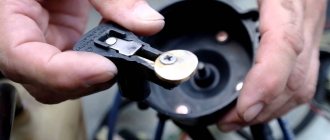
Having removed my hall regulator, I noticed that the design was slightly different from the 2112 sensor, but it doesn’t matter; when I took out the old regulator, I noticed that there was a lot of black carbon on the surface, after cleaning it, I installed it back, started it, the situation did not change! In short, the brain didn’t float and started installing a new one! Installation rules, what you need to pay attention to! When installing, watch the sealing ring so that it does not turn or bend during installation, also pay attention to the distance L between the end of the valve needle and the mounting flange - it should be no more than 23 mm. If this distance is greater, the idle speed regulator needle will rest against the throttle assembly seat and the idle speed regulator will be damaged when tightening the fastening screws. Before installing the idle speed regulator, clean the seat and air channel in the throttle assembly, as well as the surface under the idle speed regulator O-ring, from dirt. progress. In my case, the sealing ring from the 2112 regulator did not fit into the seat, so I removed the old one, and with the old sealing ring everything fell into place!
After starting the engine, the speed rose to 3000 rpm, when you pressed the gas at 4000 thousand, after 3 seconds they began to go into place)))
So don’t go straight to the point, you can change banal things like this yourself, saving money and having an interesting time! Thank you all for your attention, good luck!
I will bring tuning spare parts to order
Issue price: 100 UAH Mileage: 24,000 km
What is a camshaft sensor, the principle of operation of the camshaft sensor
To understand the operation and principle of operation of the device, you need to know where the camshaft sensor is located. The sensor is located on the side of the pump and power steering pulleys. The sensor axis always corresponds to the direction of the camshaft axis.
The camshaft sensor is a device that ensures the normal operation of the car's engine. It determines the angular position of the timing mechanism in relation to the position of the crankshaft. After this, information from the sensor goes to the engine management system to control fuel injection.
The engine control unit, having received a signal from the sensor, receives data on the position of the piston of the first cylinder. After this, the control system sets fuel injection and ignition of the fuel mixture, according to the operating order of the engine cylinders.
Reasons for sensor failure
A DPRV malfunction can occur for several reasons, and replacing it will not always solve the problem. The reasons why the device does not work may be the following:
- lack of contact between the device and the signal wire;
- the presence of moisture at the connection point of the DPRV;
- violation of the integrity of the wire, including its short circuit;
- incorrect power connection;
- axial timing runout;
- steel shavings on the device body;
- violations in the operation of the internal combustion engine control unit;
- incorrectly set gap.
What does the performance of the DPRV depend on?
The performance of the DPRV depends on the temperature conditions. Overheating will damage it. The sensor will not work if the wires through which it transmits and receives the signal are faulty, or the reference point is broken. Damage or contamination of the sensor itself plays an important role. Also, under difficult operating conditions (off-road driving, cargo transportation), the sensor may move or, even worse, a short circuit may occur. In order to eliminate sensor failure at the most inopportune moment, diagnose it and replace it after 4-5 years.
Main sensor malfunctions and their causes
The main symptoms of a malfunctioning camshaft sensor:
- the “check engine” signal comes on and driving dynamics deteriorate;
- the number of revolutions increases or decreases independently;
- a warm engine is unstable at idle speed;
- under dynamic loads, detonation occurs in the power plant;
- higher fuel consumption;
- The engine does not start.
If you notice such symptoms, check how the camshaft sensor is working. It may have failed and needs to be replaced. The causes of sensor malfunction can be: failure of the disk with reference points, displacement of the DPRV installation, short circuit inside the device, overheating of the motor.
How to check the camshaft sensor
Before checking the camshaft sensor with a tester, you need to visually inspect the sensor housing and gear rotor for damage or the presence of metal shavings. This may also be the reason for its malfunction.
Diagnostic tool
To check the camshaft sensor you will need: a multimeter/tester, pliers and a screwdriver. The multimeter/tester will guide you to perform a detailed test of the device. It will show exactly what is wrong with the sensor itself or the wiring.
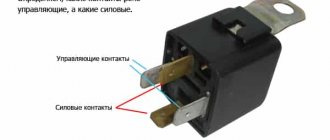
Test scheme
Before starting to diagnose the sensor, examine the connector which should have: positive, negative contacts and a contact for signal transmission.
1. Turn the ignition on and check the camshaft sensor with a multimeter. Connect the tester ground to the engine ground. The measurement must correspond to the voltage readings at the battery terminals. If the readings do not match, then the sensor's power supply circuit has failed.
2. After this, measure the voltage at the sensor ground in a similar way. The voltage should be zero.
3. Connect the positive and negative wires of the camshaft sensor. Connect the middle contact through the tester. Thus, we connect one wire of the multimeter to the signal terminal of our sensor, the other needs to be powered to the input to the control system.
4. After this, crank the engine with the starter. If the sensor is working, it will show a voltage from 0.4 to 5 volts. If the values are different, the sensor should be replaced.
If, after checking, you find the cause of the breakdown in the sensor itself, do not delay replacing it. Without it, the engine will work, but in emergency mode, fuel consumption will increase significantly, since fuel is now supplied to all cylinders simultaneously.
Care and maintenance of the phase sensor in a Lada Priora car
One of the new features in the electronic control unit of the vehicle's power plant is the phase sensor, or, as it is also called, the camshaft position sensor of the engine unit.
The standard Priora phase sensor is used to accurately identify the cyclicity of engine operation and, taking into account the information received, transmit it in the form of electronic pulses to the input connector of the on-board computer, which controls the functionality of the power plant.
Briefly, we can say that the purpose of the phase sensor is to determine the angular position of the camshaft of a car’s gasoline unit. The operating principle of this device is based on the use of the Hall effect. On the camshaft pulley of the car there is a welded and specially machined disk of the setting value.
When the disk passes through a special hole in the phase sensor, a voltage signal with a value close to the initial value (slightly more than zero value) is transmitted from the device to the on-board computer. When the disk moves through the control segment for measurements, a translation signal appears, the so-called. reference pulse, with a potential difference of about 5 Volts, which is comparable to the position of cylinder III at the compression point.
In other words, the highly sensitive element of the product responds to the configuration created by the circular rotation of the motor camshaft of the magnetic field. Such a phase sensor for Priora, the price of which is acceptable for Russian car enthusiasts, is a complex of components, where the secondary type device consists of an output cascade, designed similar to an open collector, as well as a semiconductor bridge and a pulse amplifier.
Russian car enthusiasts often ask about the phase sensor, where it is located, how difficult it is to dismantle it, etc. Please be informed that this device is located on the aft drive housing of the DOHC camshafts. Removing and replacing the phase sensor on a Lada Priora will cause some discomfort due to the “blind” search for a hole for mounting the device, but with some skill this will not be difficult to do.
In the Lada Priora car, a phase sensor is attached to both models with an eight-valve engine and those with a sixteen-valve engine. If in the first case its location is in the end plane of the cylinder head near the air purification filter, then in the other on the cylinder head near the first cylinder of the vehicle.
On Lada Priora (eight-valve) cars produced before 2005, a phase sensor was not installed. If the vehicle was not previously equipped with such a device, then this meant a change in the principle of opening injection systems, i.e. the injectors operated in pairs in parallel mode. If the device is installed on a car, then fuel injection occurs in a phased manner, i.e. a specific injector into the corresponding cylinder.
A defect in such a device and rendering it inoperative for one reason or another means that one should expect an increase in fuel consumption, an increase in the toxicity of exhaust gases and problems with diagnosing errors in this device. The main malfunctions of an electronic gadget include the following cases:
- When starting the power plant, the starter spins the flywheel for 3-5 seconds. Next, the engine starts and the “Check Engine” banner lights up on the instrument panel, which means the on-board computer is waiting to receive signals from the device.
- Excessive consumption of fuel.
- Errors in the vehicle self-diagnosis mode when operating the engine unit.
- Reducing the dynamic properties of the vehicle's power plant.
- The motor does not start.
Only replacing the phase sensor can correct the operating state of a faulty device, because Repairing this device is useless and will practically not bring the desired result. Correcting the readings of a faulty phase sensor, the price of which is low and amounts to 300-450 rubles, consists of completely replacing it with an updated product.
You can purchase such a product in specialized VAZ automobile stores selling spare parts and accessories or at branded vehicle service stations.
To replace the phase sensor, you must have a set of locksmith wrenches, tools and accessories used by drivers. The operating procedure is as follows:
- Remove the negative cable from the vehicle battery terminal.
- Using a locking device, press out the car wiring distribution block and disconnect it from the device being removed.
- Using wrenches, unscrew the device fasteners.
- We dismantle the electronic phased injection complex.
- We install the updated device in the appropriate order using the reverse algorithm.
For car enthusiasts who use Priora. Remember that if you have problems turning on the power plant, the cause may also be hidden in this inconspicuous device, which, it would seem, does not have a significant effect on the functionality of the car. At the same time, its malfunction leads to unnecessary financial expenses and loss of time.
How to replace the camshaft sensor
If you are sure that the camshaft sensor is broken, be sure to replace it with a new one. Replacing the sensor is a simple task and you can do it yourself. It should be changed every 100 thousand km. even if it is still functional. This is due to the fact that its “filling” does not tolerate overheating, and it constantly works with changes in temperature conditions. Before purchasing a new sensor, pay attention to the recommendations of specialists and use the parameters specified by the manufacturer.
Subscribe to our feeds on social networks such as Facebook, Vkontakte, Instagram, Twitter and Telegram: all the most interesting automotive events collected in one place.
Every modern car has a camshaft position sensor. It is a very important part of any vehicle as it helps ensure that the engine runs properly. The camshaft position sensor is built next to the engine just under the hood. Typically, different car manufacturers and brands have their own unique location for mounting the sensor near the engine. You can find it either at the back of the cylinder head or near the engine.
In this article we will look at DPRV. Many people confuse it with the crankshaft position sensor because they are very similar. But you must understand the difference, because they perform different functions in the car and have different symptoms and causes of problems.
Replacement
The process of replacing the sensor is a fairly simple job, but very inconvenient for 16-valve engines. Below are replacement instructions for two types of motors.
To carry out the work you will need a ratchet with a 10mm head and a 10mm open-end wrench.
Replacing DF 16 valves
- Remove the negative mark from the battery and remove the decorative engine cover with the inscription (16 VALVE)
- Disconnect the connector from DF
- We unscrew the two bolts securing the sensor, the bottom bolt is screwed into a hard-to-reach place, so you will have to work hard to unscrew it, but it is still possible. It is recommended to use an open-end wrench to unscrew the bottom bolt.
- Then remove the sensor and install a new one in reverse order.
Replacing DF 8 valves
- Disconnect the negative terminal from the battery and remove the connector from the sensor.
- Unscrew the sensor mount. In the 8-valve model, it is secured with one M6 bolt; use a ratchet to unscrew the bolt and remove the sensor.
- Install the new sensor in reverse order
Replacement completed
Remember, the Priora phase sensor differs from the 16 and 8 valve models.
We hope our article was useful to you.
What is a camshaft position sensor
The camshaft position sensor is also called the cylinder sensor or camshaft sensor. In sequential fuel injection systems, the electronic control unit must determine which cylinder should be injected next. This information affects engine operation and comes from the DPRV. As the engine rotates, the DPRV sends a signal to the on-board computer whenever a particular cylinder is at top dead center (TDC). Thus, the duration of pulse injection is estimated, for which the camshaft sensor is responsible.
In simultaneous fuel injection systems, the on-board computer is not used to determine the cylinder and injection order, since this is not necessary for the operation of the system. When a signal is received from the crankshaft or distributor, the exact cylinder is determined by recognizing the mechanical positions of the crankshaft, camshaft and valves.
Types of sensors used
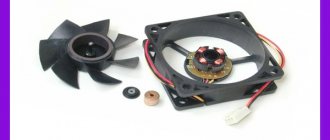
The most popular are 2 types of DPRV, which look almost the same and differ slightly in design:
An inductive sensor is needed to register the cylinder and can be located inside the camshaft. Therefore, a device with a magnet is mounted near it. Each time a magnet passes through the DPRV, its magnetic field changes and the resulting pulse is sent to the on-board computer for subsequent processing.
The Hall sensor may be located inside the camshaft. A screen with a socket and a magnet is installed on the shaft. When the screen passes between the magnet and the hall sensor, the DPRV turns on and off. While the socket is in front of the DPRV, the voltage returns to the amplifier through the third signal cable. As long as there is a solid sector of the screen in front of the sensor, the feedback voltage is interrupted as the magnetic field disappears.
Maintenance
Don't forget to regularly maintain your car by changing the cabin air filter. You should definitely change this cabin air filter at least once a year. We also advise you to treat the ventilation system with antibacterial sprays every year. To do this, having purchased antibacterial agents (preferably spray, etc.), turn on the engine and start the interior ventilation system, turning off air recirculation. Next, open the hood and spray with an antibacterial agent in the place where air is taken into the cabin. This substance, together with the air, will pass through the entire ventilation system and enter the cabin. This way you will protect yourself from the formation of harmful bacteria and microbes in the ventilation system.
Also, sooner or later you will have to replace the refrigerant in the system. Be sure to have this work performed only by an authorized dealership to avoid damaging the air conditioning system or refilling coolant that is not certified by the vehicle company.
Where is the sensor located
The location of the DPRV varies depending on the make of the car. In most cases, you can find it in the following places:
- near the cylinder head;
- near the wiring connectors on the front of the motor;
- near the toothed belt mount;
- on the rear side of the cylinder head;
- special compartment under the hood;
- inside the cylinder head.
First, consult your vehicle's manufacturer's repair manual. This contains all the necessary information.
Basic scheme for supply and exhaust ventilation with air recirculation
Engine valve knock
Most often, to organize supply and exhaust ventilation with recirculation, a scheme based on the use of a combination of a fan coil and a chiller is used. The fan coil replaces the indoor unit of the air conditioner, working as an active battery. This is a prefabricated unit in which there is a drainage system for organizing the outflow of condensate formed in the summer, a fan, a heat exchanger and an air filter. A chiller is a water heater that, depending on the time of year, heats or cools water, which then transfers its temperature to the incoming air.
The temperature of the coolant in the chiller is controlled from the control panel. This system allows for full or partial air heating in winter and air conditioning in summer. The volume of the room does not matter, since there are systems designed specifically for supermarkets and other large buildings. The advantage of this system is the ability to ventilate a large number of rooms in one building under a single climate regime. The air intake and exhaust points from the fan coil unit are routed using standard ventilation ducts.
As for recirculation control, it is carried out using remotely adjustable dampers or grilles, which are controlled from a remote control. The temperature of the incoming air varies depending on the time of year, while the temperature of the supply air supplied to the room should be comfortable. Its required value is set on the control panel. The chiller heats or cools the outside air to a predetermined value; it enters the heat exchanger, mixing with the air returned from the room, as a result of which it leaves the supply diffuser at the optimal temperature.
The amount of air that needs to be taken from the room and mixed with outside air depends on the set temperature parameters in the room. It is by this criterion that the installed position of the dampers is determined. The dampers themselves are mounted at the points of air intake from the room, as well as on the street air intake line. The dampers are controlled synchronized and carried out from the remote control. Its parameters are adjusted by specialists individually in each case.
Working principle of the camshaft position sensor
The task of the DPRV is to work with the crankshaft sensor to determine the exact position of its drive. Thanks to the combination of both sensor signals, the engine control unit knows when the first cylinder is at top dead center.
This information is needed for 3 purposes:
- To start fuel delivery during sequential injection.
- To activate the solenoid valve signal for the pump injection system.
- To control cylinder detonation.
The DPRV operates in accordance with the Hall principle. It scans the ring gear on the camshaft. Rotation of the ring gear changes the Hall voltage IC in the DPRV housing. This voltage change is transmitted to the control unit and evaluated there in order to set the required data.
Features of the principle of operation of the DPRV on Priora
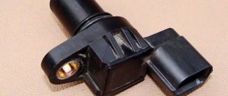
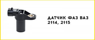
It should be noted that Priors use two types of camshaft sensors. For engines 21114 with 8 valves, it looks like this, as shown in the photo below.
They are called end caps. Below is a diagram indicating the numbers of original parts.
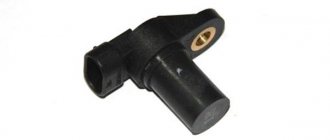
For 16-valve Priora cars, this sensor has a different appearance. The main difference is the presence of a slot (slot) at the end. Due to this gap, such products are called slotted. The photo below shows the appearance of the element.
A diagram indicating the sensor and its fastening elements is presented below.
The difference between the devices lies not only in the design, but also in their location, but you can learn about this in detail below. Next, we move on to consider the operating principle of such elements. Their operating principle is based on the Hall effect, familiar to many from physics lessons. To refresh your knowledge, below is a corresponding illustration.
Both sensors used on Priors have an identical operating principle, so next we will consider how they function using the example of 16-valve engines.
- There is a metal disk on the camshaft timing pulley (it is called a master disk). The design of this disk is not solid, but with a slot. The photo below shows a pulley with a drive disk inside. It is important to understand that this design is used on Priors with 16-valve engines.
- There is a groove (slot) in the tip of the sensor through which the disk rim passes during engine operation.
- When the slot of the master disk passes through the groove of the sensor, a low voltage pulse of about 0V is supplied to the controller (ECU). This indicates that the piston of the first cylinder is at the end of the compression stroke.
On a Priora with engine 21114, a camshaft with a cam is installed, through which the position of the valve timing is determined.
It is important to note that camshaft position sensors come in inductive and digital types. Priors use devices of the second type, which are distinguished by high accuracy and the ability to determine the position of the camshaft at the moment the engine starts.
Problems that a faulty camshaft sensor can create
The camshaft's job is to control the consumption of gasoline and the emission of vapors from the exhaust system. Compensation vanes are installed on the camshaft, which control the exhaust and intake valves. The timing belt and chain connect the camshaft to the crankshaft. The vehicle's engine control unit monitors the rotating position of the camshaft using a component called a "camshaft position sensor." Based on the information transmitted by the DPRV, the engine control unit will determine how much fuel should be introduced into the combustion chamber. There are many symptoms of a bad camshaft sensor in your car.
Ignition problems – The mixture of air and fuel in an internal combustion engine requires a spark to ignite. In some vehicles, if the DPRV fails, there will be no spark, which is the first sign of a DPRV malfunction. If you can't create a spark, then you can't start the engine. Unfortunately, it is quite difficult to determine the source of the malfunction, especially if it is a DPRV. But don't be surprised that it might be him.
Reduced Power – If the DPRV fails in a vehicle with an automatic transmission, you may experience a transmission lock-up fault. The only thing you can do is turn off the engine, wait a few seconds and start it again. This is just a temporary solution that allows you to quickly deliver your car to the nearest auto store. If you do not replace the DPRV, the gear shifting problem will definitely return.
Poor engine performance - a faulty DPRV will lead to incorrect fuel injection into the cylinder chamber. Since the engine depends on the correct mixture of air and fuel, problems will immediately arise in its operation. When you press the gas pedal, the acceleration of the car will be significantly less. You probably won't be able to go faster than 50-70 km. at one o'clock. Moreover, the car may begin to move jerkily.
Poor Fuel Efficiency – The fuel injectors will send too much gasoline into the combustion chamber if you have a bad fuel pressure sensor. At the same time, fuel consumption increases significantly, which can be noticed after the first 50 km. The breakdown is eliminated by replacing the DPRV.
Belt size
VAZ 2112 gearbox design 16 valves
The performance of the gas distribution mechanism drive on any type of internal combustion engine is important. Not only the efficiency of the engine, but also its power performance depends on this. In order for them to correspond for a long time to those declared by the manufacturers, it is necessary to carefully monitor the condition of all components and assemblies of the motor. Any Priora timing engine has a toothed belt in the drive. Its length, width, and number of teeth depend on the type of power unit installed on the machine.
You can find out which part is on the car from the car’s operating instructions, or dismantle the old one and carefully study it.
If a VAZ 2108 engine is installed, then it will have 111 working teeth with a width of 19 mm.
The VAZ 21126 engine has two camshafts in the timing belt, so the length of the drive increases. The number of teeth on such a product will already be 137, and the width will increase to 22 mm.
Possible causes of malfunction
DPRV is a pulse generator that creates a very weak signal. There is a small chance that the current will gradually weaken the integrity of its winding. However, vibrations caused by magnetism travel through the gear teeth. When the camshaft is turned, the force changes just like the signal generated. These vibrations cause microscopic movements within the DRV, creating weak points in essential parts, especially the winding in the case of inductive type DRV.
With a Hall-type sensor it is a completely different story. This type of DPRV is a solid-state device, that is, its electronic component, such as a diode or transistor. Voltage can damage the sensitive parts of the DPVR. Short circuits and incorrect connections can also damage it. And remember that you need a polarity sensitive power supply.
Hood with recirculation is an exhaust and ventilation device
While when using a flow hood, dirty air leaves the room through an air duct, a recirculation hood has a completely different principle of operation.
Here, there is no element such as an air duct, and the device itself is equipped with effective catch filters. When passing through them, the air is freed from all harmful microimpurities and unwanted odors, and then again supplied to the room.
How does a recirculating hood work?
The recirculation type hood operates in a closed cycle. In fact, it can only be called an exhaust device conditionally, since it does not remove air from the room, but only cleans it and returns it back. Contaminated air enters the device body under the influence of draft created by the fan blades rotating in a plane horizontal to the surface of the kitchen stove.
Moving along a given path, the air mass collides with the coarse filter. Having passed through it, it leaves fatty inclusions, particles of soot and dust on its fine mesh surface.
A hood of this type will help out when the ventilation system of the house is not working at full capacity or the ventilation ducts are so clogged that there is no draft in them at all.
Next, the air flow, under the influence of pressure, passes through a fine filter, where it gets rid of odors and traces of the smallest particles, then returns to the room. This filter is an ordinary cartridge filled with granular carbon. The carbon filter is a disposable product, so when it becomes dirty, it must be replaced.
Since this type of hood does not interact with the ventilation system, designers have developed telescopic hoods. During operation, they create a powerful lateral draft, due to which all dirty air masses are sucked in. As soon as the need for this disappears, the device hides in the countertop. This solution is not only original, but also very convenient.
How to check the camshaft position sensor
When troubleshooting a suspected DPRV fault, you should follow the diagnostic guidelines in the vehicle manufacturer's literature to isolate the faulty component when a DTC is present. There is no other way to know what is causing the problem (spark, bad ignition module, coil, computer, bad wiring or ignition switch).
Magnetic DPRVs can be checked by disconnecting the electrical connector and checking the resistance between the terminals. For example, on a GM 2.3L Quad 4, the sensor should show a voltage between 500 and 900 ohms. When testing DPRV, always take into account the technical specifications of the vehicle manufacturers. Obviously, if you see zero resistance (short circuit) or infinite (open) resistance, this means that the DPRV is not working and needs to be replaced.
Articles
Instead of the numbers 2112-3706040, the article number 21120-3706040 is found. Both designations are correct. You can also find an article with the numbers -00, -01, -02... This is how the manufacturer is designated: 01 and 03 - “SOATE”, 00 - “Autoelectronics”, etc.
Parts with article number 2112-3706040-04
Recently, flexible lead sensors have been launched. The length of the wires is 15 cm. So far there is nothing like this in retail. But the article numbers remained the same - 2112-3706040-XX.
Testing a two-wire inductive sensor
There are a number of common signs of a faulty DPRV. If you have these problems, you may need to replace it. These same symptoms can be caused by problems with the ignition or fuel injection systems. Thus, before replacing the DPRV, it is worth conducting tests to determine the real source of the malfunction.
If the check light comes on, your ECU is recording a trouble code. You can check for errors using a special diagnostic tool. Codes between P0335 and P0338 correspond to DPR problems.
This is probably the easiest and most accurate way to test and determine the problem of the DPRV. Unfortunately, the DPRV, as a rule, fails much earlier than the corresponding indicator lights up. To be constantly aware of the car's problems, it is worth conducting other types of testing.
RPM is the next method for checking the DPRV, which also requires a diagnostic tool. One of the scanner settings allows you to read the engine speed in revolutions per minute (RPM). Set up the scan tool to read engine speed and start it. The scan tool should read between 100 and 500 rpm. A low value indicates that the DPRV is not working properly. “0” means that the DPRV is completely out of order.
Multimeter testing
Of course, not everyone has access to a scanner (although they can sometimes be rented from parts stores). A multimeter is a more common and very useful tool for diagnosing many of your vehicle's electronic components. The multimeter can measure voltage, current and resistance.
You can remove the DPRV and then check the resistance. Attach one end of the multimeter to each DPRV wire. A resistance of 0 means there is a short circuit. Infinite resistance means there is an open circuit. Any of these readings indicate that the DPRV is not working. For any other value, check the manufacturer's instructions. If the reading does not match the recommended resistance, you must replace the DPRV.
How does a car air conditioner work and much more?
It seems to you that the air temperature outside the window is a billion degrees and the asphalt is melting. At this moment you remember the winter cold and snow. You want to breathe cool air. Fortunately, most modern cars are equipped with air conditioning. This allows us to travel by car comfortably even in unbearable heat. But do you know how to use air conditioner effectively?
Turning on the air conditioner in a car has become such an unnoticeable action in ours. We sometimes don't notice when we turned it on. It's like a reflex. Most of us don't even know how the air conditioning system in cars works. Because of this, we often do not use it effectively and do not know how to use it correctly.
Car manufacturers have tried to make air conditioning control as simple and uncomplicated as possible. All you need to do is turn it on and set the required temperature. The air cooling system does the rest for you. But in order to use a car air conditioner more efficiently (for example, to save fuel, which is consumed much more when the air conditioner is on), you must adhere to certain rules.
Our online publication offers you some tips on how to effectively use the air conditioner in your car. But first, let's find out how the air conditioning system works in modern cars.
The automobile air cooling system is a closed circuit in which there is an area of high and low pressure. In the section of the circuit where there is high pressure, the refrigerant (the cooling chemical in this area is in a gaseous state) moves through the system through a special compressor, which is connected by a belt drive to the engine
Have you noticed that when you press the “AC” button (turn on the air conditioning), there is a noise under the hood
This turns on the compressor, which supplies the refrigerant gas to the condenser (radiator), which cools the heated gas, turning it into a liquid state.
Then, on the low pressure side, the liquid, which is under high pressure, flows through the valve into the evaporator. This is where the magic happens. The coolant in the low pressure area has a very low boiling point and when it reaches the evaporator (actually a simple radiator that is located behind the center console) it immediately turns into gas. This process is called evaporation.
If you think back to high school, evaporation is an endothermic process, which means heat is absorbed as it evaporates. Therefore, the evaporator, which is located behind the dashboard, cools the air entering the cabin from the street through the ventilation system.
This cycle then repeats over and over again.
Now that we've learned (for those who didn't know) how air conditioning works in a car, let's take a look at a few tips to learn how to use your air conditioner more efficiently.
Checking three-wire DPRV
Steps to test a three-wire DPRV:
- remove the air filter cover;
- disconnect the 3-pin connector in the DPRV;
- turn on the ignition;
- using a multimeter and cables from the kit, measure the voltage between terminals 1 and 3 of the sensor connector;
- recommended value: 4.5 to 5.5 V;
- turn off the ignition;
- check the wires between the test box and the 3-pin open circuit connector;
- Recommended wire resistance: max. 1.5 Ohm;
- check the wires for short circuit, to battery (+) and ground (GND);
- If the wires and voltage are ok, replace the camshaft position (CMP) sensor.
IMPORTANT! Before starting any test, the battery voltage must be at least 11.5 volts.
- disconnect the 3-pin camshaft position sensor connector;
- switch DMM to voltage measurement position;
- connect the DMM between the external terminals of the connector;
- Switch the ignition to the “ON” position, but do not start the engine. You should see a minimum of 4.5 volts;
- Now turn the ignition “OFF”;
- connect the VAG 1598/22 test unit to the ECM connector;
- Check the wiring between the test block and the ECM connector using the wiring diagram. Checks must be performed on each of the following points:
- Wire 1 and socket 11.
- Wire 2 and socket 76.
- Wire 3 and socket 67.
- For each of the above tests, the maximum resistance should not exceed 1.5 ohms.
- Check all wires for short circuits.
- when connected and there is voltage between terminals 1 and 3, replace the camshaft position sensor.
- If the wiring is OK but there is no voltage between terminals 1 and 3, replace the ECM.
IMPORTANT! Before starting any test, the battery voltage must be at least 11.5 volts.
- disconnect the 3-pin wire connectors from the camshaft position (CMP) sensors;
- connect the DMM to measure voltage on terminals 1 (+) and 3 (ground) of the CMP connector using the adapters from the test kit;
- turn the ignition to the “ON” position, but DO NOT start the engine;
- Measure the voltage between terminals 1 and 3. It should be a minimum of 9.0 volts;
- turn the ignition “OFF”;
- connect the test block to the ECM connector;
- Check the wiring for open circuit between the ECM and the 3-pin connector according to the wiring diagram;
- For the CMP sensor connector on the right cylinder head, measure the following:
- Connector 1 with ECM connector 11.
- Connection terminal 2 to ECM76 connector.
- Connector 3 with ECM 67 socket.
- maximum resistance should not exceed 1.5 Ohms;
- For the CMP sensor on the left cylinder head, measure the following:
- Connector 1 with ECM connector 11.
- Connector 2 with ECM 44.
- Connector 3 with ECM 14.
- for each of these tests the maximum resistance is 1.5 ohms;
- If the wiring and voltage at terminals 1 and 3 are OK, replace the camshaft position sensor;
- If the wiring is OK but there is still no voltage at terminals 1 and 3, replace the ECM.
Functional test of the CMP sensor:
- To perform a functional test of the camshaft position sensor, disconnect the 4-pin connector from the ignition coil and check the DTC memory;
- check the supply voltage of the camshaft position sensor and make sure that it is in order;
- move away the rubber connector of the CMP sensor (the sensor remains connected);
- connect a voltage tester between terminals 1 (+) and 2 (phase);
- start the engine for a few seconds;
- for every second engine revolution, the voltage tester should flash briefly;
- if the voltage indicator does not blink, turn off the ignition and disconnect the 3-pin connector from the camshaft position sensor;
- connect the test block to the ECM connector;
- Check the signal wire for continuity between terminal 2 and socket B2. The maximum resistance should not be more than 1 ohm;
- If the specified value is not obtained, check for a short or open circuit in the wiring between the CMP sensor connector and the ECM;
- if the wiring is ok, connect the DMM between the B2 test block socket and ground;
- turn the ignition key to the “ON” position. Must be at least 4.0 volts;
- if the specified value is not obtained, replace the ECM;
- If a value is obtained, replace the camshaft position (CMP) sensor.
About the consequences of a malfunction of the Priora DPRV
The phase sensor on the Priora affects the correct functioning of the engine. The malfunction of this element leads to a number of the following negative consequences:
- Reduced power and dynamic performance. This is due to the fact that when the ECU does not receive a signal from the DF, it goes into emergency mode. In this case, not phased fuel injection occurs, but pairwise parallel injection.
- Fuel consumption increases by approximately 10-20% (0.5-1 liter).
- The engine warm-up speed decreases, which leads to frequent turning on of the cooling fan.
- Problematic or prolonged engine starting (starts up 2-3 seconds after turning the key).
- Reduced service life of the catalytic converter, the cells of which receive unburned fuel and are burned.
That is why it is extremely important to pay attention to this element. The cost of the product is low, but in order to correctly determine that the above consequences arise due to a malfunction of the phase sensor, you need to pay attention to the characteristic signs.
Repair
Before checking the DPRV or before starting any independent actions, you need to familiarize yourself with the connection diagram for the VAZ 2110 camshaft sensor, as well as the features of its installation in the engine body.
The type of action performed depends on what signs of malfunction have been identified:
- if there is visible mechanical damage to the wiring or exposure of live parts, it must be replaced, but repairs in the form of re-insulation of the wires are also possible;
- If the sensor is mechanically damaged, it must be replaced. It is not recommended to repair or disassemble it;
- if the connector is dirty, it is necessary to reconnect with a visual inspection and cleaning of the electrical contacts;
- Wear of the connection connector requires its maintenance or replacement of the sensor. Maintenance consists of ensuring a tight fit of the connected parts;
- When checking the electrical wiring or sensor with a voltmeter and identifying deviations, it is necessary to replace the faulty element. When connecting the voltmeter probes to the electrical power contacts, the sensor resistance should not be lower than 550 Ohms or higher than 750 Ohms;
- If an internal malfunction of the sensor is detected during computer diagnostics, it must be replaced.
Replacing the DPRV is carried out by disconnecting it, dismantling the faulty one, installing a new one and reconnecting the power connector.
It is important to note that after performing any actions aimed at eliminating identified faults, it is necessary to recheck the engine operation. The operating manual does not recommend disabling the sensor yourself and further operating the vehicle. The operating manual does not recommend disabling the sensor yourself and further operating the vehicle.
The operating manual does not recommend disabling the sensor yourself and further operating the vehicle.