Turn on the electric motor of the stand and bring the rotor speed to min.
Therefore, if its elements fail, it is recommended to replace the rectifier unit as an assembly. External inspection External inspection reveals obvious damage.
The relay regulator monitors the voltage level and controls the excitation current of the generator. This happens due to the fact that the current supplied to the excitation winding increases, as does the amount on the application terminal. How is the G-222 generator connected from a VAZ-2105 to a VAZ-2106. If the voltage is normal, then the old voltage regulator is damaged and needs to be replaced.
Removing the generator It is more convenient to carry out work on an inspection ditch or a lift. If the voltage corresponds to the norm, this will mean that the old regulator has become unusable.
If the indications are different, it is better to replace the regulator. Checking the rectifier unit for a short circuit Remove the wire from the terminal of the voltage regulator.
However, if the noise level is quite strong, then the following problems with the device are possible: failure of the bearings; short circuit between the turns of the stator coils; noise from brushes.
Disconnect the wire tip from the voltage regulator terminal.
How to connect an 80 A, 90 A generator on a penny (classic) part 1.
Shendys › Blog › Mounting block 2104, 05 and 07
What is the difference between the mounting blocks on the VAZ-2104, 2105 and 2107.
Unfortunately, I don’t have complete information, so we’ll look into the main differences. Finger fuse block that everyone replaces
All blocks for classics differ in the connection of fuse 9, the connection of relay winding P4, as well as the presence/absence of contacts on relays P3 and (or) P4. And let's begin:
Changes with fuse 9
On cars with a G-222 generator (used until 1987), fuse 9 was connected to the ignition and, through Ш11/3, fed the generator relay-regulator. The voltage was controlled by a voltmeter, and the charge lamp has not been connected since 1985. And on the instrument panel 2105 it could still be connected in different ways (to plus or minus).
When they started installing generators from the VAZ-2108 (37.3701), there was no need to supply power. The generator was excited through a charge lamp, and it was powerful (the generator would not have been excited through a small one). Fuse 9 was connected to the rear fog lights, the circuit Ш3/3 - Ш13/1 from the fog lamp button to the lights broke.
There are also rear fog light relays (located in the cabin next to the mounting block). The fog light button is not locked and is controlled by a minus sign; press and release - the fog lights turn on (if the lights are on). Pressed and released again - turned off. And if you forgot to turn it off, they will turn off themselves when the lights are turned off. ZPTF circuit with relay for VAZ-2105, VAZ-2107
Means
, if when replacing the unit the charge was lost (there is an old G-222 generator), we connect the orange wire from Ш11/3 to the orange one next to it - Ш11/4, and the regulator will be powered along with the instruments and turn signals.
The difference is in the connection of audio signals
The signals are of type 2101 (there is a constant plus from fuse 7 on Ш6/7 and are controlled by closing the button on the steering wheel with a minus - there is a jumper on pins 85 and 87 instead of relay P3). And there are signals of type 2106 (the signal housing is connected to the body, and they are turned on by applying a plus from the relay, which is turned on by a button on the steering wheel).
Means
, if in the old block there was a jumper instead of relay P3, we put it in the new block, and vice versa - if there was a relay, then there should be a relay in the new block.
Differences in connecting the engine fan
On older machines, the fan was controlled by relay P4. It turned on if the ignition was turned on when minus was supplied from the sensor through Ш7/7 and it supplied plus to the fan through Ш6/6.
And on modern cars with the EURO-3 toxicity system, there is a mounting block where the fan relay winding is connected to the pad wear circuits and the oil pressure indicator, which go to the injector
Means
When replacing a mounting block, if there is a jumper in the old block, we put it in the new block and that’s it. If there is a relay in the old one, then it should be in the new one. If the fan turns on then it's normal. If it doesn’t, it means you got the wrong block, you need to: 1) reconnect the white-black wire from Ш7/7 to Ш7/6 (the empty leg is nearby, between the black-white and blue-white wires). If there is a pink-black wire going there, we cut it, and another pink-black one at Ш10/4 and in the interior at Ш3/8, thereby turning off the pad wear indication (if necessary, we connect the cut wires together directly). 2) Connect Sh8/7 to the plus, for example to Sh6/7, or Sh6/8, or Sh6/4 or Sh11/4. If there is a gray-white wire from the oil sensor on Ш8/7, we disconnect it and connect it directly to the devices (instead of the gray-white red block that needs to be insulated, we lead the wire through the rubber seal of the headlight range control tubes, there is enough length to spare). 3) If all else fails, re-start the fan using the photo ad-cd.net/XMAAAgJ2v2A-1920.jpg
Relays and fuses
K1 - Relay for turning on the heated rear window K2 - Relay for the headlight cleaner and washer (5-pin) Or maybe a starter relay KZ - Relay for turning on the sound signals (or jumper) K4 - Relay for turning on the electric cooling fan (or jumper) K5 - Relay for turning on the high beam headlights KB - Relay for low beam headlights
F1 (10A) - Reversing lights. Heater electric motor. Indicator lamp and rear window heating relay (winding). Rear window wiper and washer (2104) F2 (10A) - Electric motor for windshield wiper and washer. Electric motor for headlight cleaner and washer. Windshield wiper relay. Headlight cleaner and washer relay. F3 (10A) - Reserved F4 (10A) - Reserved F5 (20A) - Rear window heating strips and power contacts of the heating relay. F6 (10A) - Cigarette lighter. Clock (if any). Plug socket for a portable lamp (if available). Open door alarm lights (if equipped) F7 (20A) - Sound signals. Engine cooling fan (if equipped). F8 (10A) - Direction indicators in hazard warning mode. Switch and relay interrupter for direction indicators and hazard warning lights in emergency mode. F9 (8A) Generator voltage regulator. (only for generator G-222) OR F9 (10A) - rear fog lamp circuit. F10 (10A) Turn indicators in turn indication mode and the corresponding warning lamp. Generator voltage regulator (except G-222). Instrument cluster. Carburetor pneumatic valve control system. Parking brake warning lamp relay (if equipped). F11 (10A) Brake light lamps. Lamp(s) of interior body lighting. F12 (10A) Right headlight (high beam). Coil of the relay for turning on the headlight cleaners (with the high beams on). F13 (10A) Left headlight (high beam). Indicator lamp for turning on the high beam headlights. F14 (10A) Left headlight (side light). Right rear light (side light). License plate lights. Engine compartment lamp. Indicator lamp for turning on side lighting. F15 (10A) Right headlight (side light). Left rear light (side light). Cigarette lighter lamp. Instrument lighting lamp. Glove box lighting lamp. F16 (10A) Right headlight (low beam). Coil of the relay for turning on the headlight cleaners (with the low beam on). F17 (10A) Left headlight (low beam). Rear fog lights (if connected to low beam).
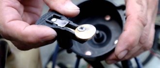
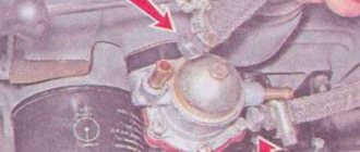
Transition from an electromagnetic-thermal relay to an electronic one.
This “barrel” is located under the dashboard of a car. This is an electromagnetic thermal relay. Due to short-term operation (1-2 months), it is recommended to replace it with an electronic one. After this time, it begins to burn or shorts out.
The following are the steps to replace it:
- disconnect the contact terminals;
- We mark each wire with a marker, or use paint to highlight it in different colors;
- contact No. 1 of the electronic relay is connected to the wire with the x sign;
- Contact No. 2 of the electronic relay is connected to the wire marked L;
- contact No. 3 of the electronic relay is connected to the wire marked P;
- Contact No. 4 is ground, we connect it to a separate wire.
All this work must be carried out when using heat shrink.
The replacement of incandescent lamps with LEDs in direction indicators is gaining great popularity due to the fact that incandescent lamps are much inferior to LED lamps in terms of service life and light output.
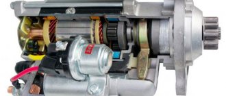
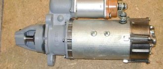
Starter VAZ 2104
The VAZ 2104 has not been produced for many years in a row, but is seen relatively often on the roads. The engine is started using a starter.
This part fails relatively rarely, but due to how long the machines have been produced, it has to be replaced relatively often. It is important to study possible breakdowns of this equipment in advance.
Contactless ignition system
The ignition system (IS) serves to create a pulse voltage and timely ignite the combustible mixture in the combustion chambers of the power unit. It is the main part of the vehicle's energy supply system.
The evolution of the “seven” ignition began with a contact-type mechanism. Its feature was the process of generating an electrical impulse using a group of contacts located in the distributor. The constant mechanical and electrical loads to which the contacts in such a system were subjected led to the fact that car owners very often had to clean them, change them and adjust the gap between them. In principle, this was the only significant drawback of contact-type ignition, and drivers, when problems arose with ignition of the mixture, knew exactly what needed to be checked and repaired.
In the early 90s of the last century, the “seven” received contactless ignition. It made the life of the owners of these cars much easier, because in its design there were no longer any burning contacts that required constant adjustment. They were replaced by an electronic switch that does not require any maintenance.
The design of the contactless ignition system and the principle of its operation
The contactless ignition system (BSI) of the VAZ 2107 includes:
- electronic (transistor) switch;
- transformer coil (two-winding);
- distributor (distributor) with Hall sensor, contact cover and slider;
- set of high-voltage wires;
- candles.
Each of these elements is a separate part and performs its functions independently of other components. Sparking in a VAZ 2107 engine with a non-contact ignition system occurs according to the following algorithm:
- When voltage is applied to the starter, its rotor begins to rotate the crankshaft, which, in turn, rotates the distributor shaft with the slider.
- The Hall sensor reacts to this rotation, registers the rotation of the distributor shaft and transmits a signal to the switch. The latter, having received a signal from the sensor, turns off the current supplied to the primary (low-voltage) winding of the coil.
- At the moment the current is turned off, a powerful voltage pulse occurs in the secondary winding of the transformer, which is transmitted through the central wire to the slider (moving contact) located at the end of the distributor shaft.
- The slider, moving in a circle, alternately comes into contact with four fixed contacts located in the distributor cover. At certain moments, it transfers tension to each of them.
- From the stationary contact, current flows through a high-voltage wire to the spark plug, causing sparking at its electrodes.
Reasons for starter failure on a VAZ 2104 and ways to solve problems
There are many reasons why a starter may simply stop turning. But all the causes of failure can be divided into main categories:
The main purpose of the equipment of this type is the conversion of electrical energy into mechanical energy. This allows the engine flywheel to rotate. Which leads to its launch. Mechanical problems arise in the following components:
The starting process itself is based on the engagement of the Bendix gear splines with the engine flywheel. Over time, the splines fail and wear appears on them. In some cases, during stressful use and frequent starts, the teeth may simply be broken. Which leads to poor engagement or complete lack of contact between the starter and the flywheel. Such a breakdown can only be resolved by replacing the bendix.
Another problem is bearings. You can check the serviceability of these without disassembling the starter. But you will definitely need to remove it. If, after dismantling, when trying to rotate the shaft, it turns out that it does not rotate, then the bearings have failed or are severely worn out. It is usually difficult to replace it yourself. A special stand is required, as well as a key remover. It is due to this that dismantling is carried out.
The electrical component also often fails. The reasons may be as follows:
- there is no contact at the control terminals of the solenoid relay;
- The stator winding has failed.
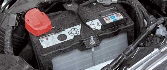
Why is the battery charge light dim?
If the lamp burns dimly, then the generator voltage is less than the battery voltage, i.e. ... If the lamp burns dimly or blinks with a known good battery, then the reason is in the generator (brushes or voltage regulator) or its harness - the belt or charging wire.
Interesting materials:
How to smooth corners in Corel Draw? How to group pictures in Excel? How to group a table? How do husband and wife sit at a wedding? How much does Stapel shrink? How hard does the kebab cook? How to sync sounds to iPhone? How to scan to Canon 4410? How to scan with HP Ink Tank 315 printer? How to scan directly into Word?
Original parts and their analogues: which is better
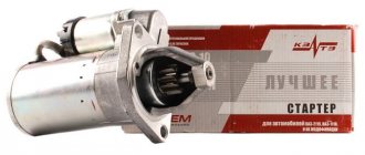
Purchasing a new starter is a good decision. As is the case with other parts, there is always a choice between original and analogues. Purchasing original AvtoVAZ products is preferable. Its price is not always high. At the same time, the overall dimensions and mounting holes are 100% consistent.
Characteristics of the original starter for the VAZ 2104 car:
| Manufacturer's name | vendor code | Options | Cost, rubles |
| AvtoVAZ | 2107.3708000-01 | 12V 1.2kW z=11 | From 4 900 |
There is a wide selection of different analogues. It won't be difficult to buy them. Moreover, some manufacturers produce products in quality that are not inferior to AvtoVAZ. It’s just important to remember that well-known brands are often counterfeited. That is why you need to familiarize yourself with the characteristics of such products in advance. Analogues that have proven themselves to be positive:
| Manufacturer's name | vendor code | Options | Cost, rubles |
| Bosch | 0001362059 | 12V 1.2kW | From 2700 |
| Valeo | 0001367008 | 12V 1.2kW | From 3 400 |
| Delco | 0986016200 | 12V 1.2kW | From 3 000 |
Official website of the VAZ 2101 car club in St. Petersburg Archive
Pros: More accurate. They don’t melt, but they snap off. They don’t interfere (if you’re tall) They look more aesthetically pleasing + 3 fuses in a standard block size, and the main thing is that there will be fewer problems with the electrics, because the new ones have much better contact and the tabs holding the fuse won’t bend.
We will need:— GAZ 3110 fuse block—Female terminals—Insulating tape, heat shrink.—The fuses themselves. There are 10 pieces in a standard block. 1 for 16A and 9 for 8A Here we need 1 for 20A and 9 for 10A, these denominations are as close as possible to what they were (the new model works much more accurately), I’ll get to the choice of denominations later.
Here is the block itself.
and this kind of garbage happened when I pulled out the fuse...
Luckily I took some spare ones.
First, let's remove the mass from the Akuma. Next, I removed the old fuses and unscrewed the block.
Tried on a new block
From the beginning I almost didn’t fit, but with the help of this miracle tool
everything fits as it was, if you straighten it, don’t overdo it, the ears are very fragile. I had to bend it maybe 0.5cm, so it’s not critical.
The old unit had jumpers inside between the fuses, but this one does not. And we need to make them. We need to make them between the 3m and 4m, 5m and 6m, 7m and 8m, 9m and 10m fuses. You can look at the electrical diagram, which was becoming clearer. Everyone makes jumpers in their own way. Someone bends the ears on the block. Someone solders a piece of wire. Etc. Let's consider 2 options. 1) More popular. Clubmate ChesnoK did this. He made these “jumpers”
Quote
It was made very simply: two “mothers”, wires about 3-4 cm long, a soldering iron, solder, rosin and a heat pipe.
2) Option as I did. I took these terminals
and with the help of the above-mentioned miracle instrument made this out of them
They acted as jumpers, legs on the new block nearby, so these fit perfectly.
Next, we throw the wires along the 1st, putting heat shrink on the old wires, because
on the new one the wires will be much closer and it’s better to be on the safe side. ATTENTION! This is the most crucial moment. Don't mix up the wires! It’s better to throw 1 at a time and check each one once. If you confuse something, it can lead to unnecessary hemorrhoids later.
Alternatively, you can sign all the wires
If you confuse something, it can lead to unnecessary hemorrhoids later. Alternatively, you can sign all the wires.
Here are all the wires in the new place
The previous ones took their place
In principle, the entire installation took me 30-40 minutes without rushing... And studying the wiring. Very comfortable, the fronts don’t stick out
and most importantly, there are 3 free ones, I personally need them right now for the electric fan and maybe for heating (if I can get glass).
About fuse ratings.
In the old block there were 1st - 16A, the rest - 8A. The ratings in the new one are closest 8A-10A, 16A-15A. BUT knife ones are more accurate! Therefore, you can put a higher denomination. On this issue, a certain MegaVolt from the Moscow forum carried out “scientific work”
Quote
You can also plug in 10A red ones into the low-high beam circuits, if only the lamps are of the original power; for 90/100W lamps - blue 15A ones.
But by and large, it is better to find an ammeter up to 50A and, by removing the fuse and connecting an ammeter instead, turn on all consumers that are on this fuse. Record the current value and install a fuse with a nominal size larger...
Total: block - 220r; fuses - 3r/piece; heat shrink somewhere - 60r. package
Happy installation.
Starter replacement and installation procedure
Before removing the starter, you need to figure out where this device is located. The easiest way to do this is using the photo from the manual. Dismantling this equipment usually does not cause difficulties. Removal requires only a set of wrenches, WD-40 and a little patience. The procedure usually takes no more than 1 hour. Removing the starter from a VAZ 2104 car includes the following main steps:
- it is necessary to disconnect the battery terminals - in some cases it is enough to disconnect the negative terminal;
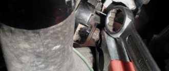
- Next you will need to unscrew the bolt securing the starter shield - use a 10mm wrench;
- the starter itself is attached to the clutch housing using 3 bolts - you can unscrew them using a 13mm socket;
- using the same 13mm socket with an extension, you will need to unscrew a couple more bolts securing the crankcase shield;
- the terminals securing the starter wires are disconnected - the block itself is then removed.
Next, the starter is simply pulled out through the engine compartment - as in the picture below.
Installing a new starter or the old one after repair is performed in the reverse order. You need to familiarize yourself with all the subtleties and nuances in advance. It is important to note that the composition of WD-40 is a dielectric.
After unscrewing various threaded connections, it is necessary to remove it from the contact points. Otherwise, startup problems may occur. Also, threaded connections should be lubricated with graphite lubricant. This will avoid problems later when removing the starter.
Source: zapchasti.expert
starter | Topic Author: Toiba
the starter does not turn the relay clicks on the premium screwdriver carotyl sparks go it clicks but does not turn what to do run for new starters
Dmitry (Armen) When I had such garbage, I changed the starter, but left the old one, I’m also waiting for an answer from the person who encountered this and I figured out what was wrong
Alexey (Aurora) I have the same issue. everyone says the contact is crappy, but I also think there’s a capacitor in there that’s leaking brains
Dmitry (Armen) Well, I don’t know about the contact, the wire is specifically tightened there, if it had been unscrewed, then the starter would not have turned at all, it happened to me that until the engine cooled down, when I turned the key, I could hear a quiet click like a relay, but When the engine cooled down it started normally. It seems to me that this retractor is most likely delusional
Kostya (Birtie) I’ll give you a hint: throw your fours in the trash =) the joint is in the car itself =) or sell it and buy a used bike with the money you learned =))
Dmitry (Armen) Listen to the joker, tell you where to go. Go to maxidom)))) Or play another game of line, maybe someone there will give you a brain, and then you will understand all your stupidity.
Alexander (Stesichore) This retractor is clearly screwed, buy a new gear starter, it turns faster and is smaller in size, and it’s inexpensive.
Vitaly (Tristen) but it seems to start fine for me)))
Nikolay (Theophila) Gearbox dies quickly FACT!
Nikita (Chikae) Khan's brushes on the starter stopudov. Or the armature (rotor). In the removed position, apply minus to the body, and plus to the contact, nothing happens. Disconnect the wires, turn the shaft a little by the bendix, plug it in again, if it spins, it means part of the winding on the rotor has burned out (the worst option - it happens after long starts in the cold) If it doesn’t spin, the brushes are either run out or stuck in the sockets, i.e. . replacing them or eliminating the cause of jamming. If you have any more questions, please ask, I specialize in starters and generators
Oleg (Solveig) I have the following question - 20 it starts right away, I turn it off and that’s it. The relay clicks but the starter doesn’t turn. It cools down and starts again. a week ago (before the frost) something like this already happened, I removed the starter, cleaned the contacts, it was cured. Now I started to blame the battery, I bought a new one, it didn’t help - everything is the same. I can’t think of anything to do. The starter is fine, the battery is completely new. Please explain to anyone in the know.
Nikita (Chikae) check the contact of the starter brush assembly with the housing - this is the place that often frays the brain and gives rise to malfunctions like “OK when cold, bad for hot” and vice versa
Oleg (Solveig) thanks. I'll try.
Alexey (Aurora) change the traction relay.
Oleg (Solveig) retractor seems to be in order.
Oleg (Solveig) definitely wired to ground. I did everything, thanks to everyone.
Nikita (Chikae) Contact me, friend
Andrey (Liliana) There is no mass between the body and the engine.
Kristina (Mikel) when trying to start the starter buzzes strangely, after several such attempts it still starts. what could it be?
Nikita (Chikae) we need to change the drive gear in the starter - in common parlance “Bendix”, we disassemble the starter and take the sample to the store
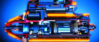
How it works
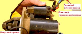
Plus, when the contacts on the traction winding are closed, the starter motor is supplied with power from the battery. The contacts are washed out, the blocking is activated, due to which the retractor winding is “cut out”.
The retractor is controlled directly from the ignition switch. Plus it plays the role of starter protection. The fact that the relay will require an impressive amount of current leads to gradual wear of the contacts in the contact group.
This can be noticed by the unclear start of the power unit; periodically the starter may not operate or may rotate the engine slowly. You can solve this problem on your own.
Typical breakdowns
Now let’s figure out how to check the starter solenoid relay on a VAZ 2110. It must be carefully inspected after dismantling.
This unit is characterized by certain breakdowns, which we will talk about.
- The fastening is loose or the nuts responsible for fastening the wire end are completely loose. Everything is simple here, as you understand. You just need to tighten the fasteners.
- Oxidation has formed on the windings, connections or wiring. If everything is not too serious, you can simply clean the contacts. In case of serious oxidation, it is better to replace them with new ones.
- The power supply circuit has breaks. Again, you don’t need to come up with anything fancy, just replace the chain.
- The armature exhibits idle operation or slow operation. Just replace the armature and that's it, problem solved.
- Check the short circuit of the turns of the two windings using an ohmmeter.
Historical reference
The VAZ 2101 platform was taken as the basis for production. At its core, it was the same rear-wheel drive five-seater sedan car. The VAZ 2105, with its design, practically copied the models of cars produced in Europe in the early 80s, and cost an order of magnitude lower, which predetermined its popularity in Western countries.
The price of the VAZ 2105 was the lowest among rear-wheel drive models
Abroad, the car was named Lada Riva and Lada Nova (depending on the country of sale). Under these names he was shown in video advertisements.
Windshield wiper device
In order to repair non-working wipers of a VAZ 2107, you need to know the structure of the windshield wiper (the author of the video is Avtoelektrika HF).
Schematic diagram of a glass cleaner
On sevens, a windshield wiper of the SL-193 type is installed. It is located in the engine compartment in the heater air plenum box. Its electrical circuit is similar to the electrical circuit of the glass wipers on the VAZ 2106.
Electrical circuit of the purifier
- fuse;
- electric motor of the unit;
- fuse box;
- a switch that supplies water to the glass;
- a switch that changes the speed of movement;
- relay;
- egnition lock.
The windshield wiper consists of a lever mechanism, brushes, levers and an electric motor with a gearbox. The mechanism is turned on using a switch on the steering column, which also turns on the washer motor. Thanks to the motor and gearbox, a rotational movement is created that drives the trapezoid.
VAZ cleaner gearbox
The shafts are connected to the gearbox by rods and transmit oscillatory movements. As a result, the brushes move across the surface and clean it of dirt.
A washer is installed to remove dirt. The design of the VAZ washer includes: a motor, a pump, nozzles and a reservoir. The motor starts the washer pump, which pumps up the fluid in the washer reservoir. It sprays onto the glass through the nozzles.
A FEW WORDS ABOUT THE NEW PRODUCT
The modernized unit completely coincides with the old product in all respects, the diagram of the VAZ 2105 mounting block of the new model is no different from previous releases. Its main difference is that fuses of a new type began to be used. Cylindrical products were replaced by blade fuses. They have a larger contact area, so their reliability during operation increases. They are standard and used on many modern cars.
New model mounting block (for VAZ 2105)
The figure shows a new block, where its differences from the old product are clearly visible. It is installed in the regular place of the old unit. Connectors with wires are connected in the engine compartment from the bottom of the block, and the second part will be installed from the passenger compartment, in the area of the glove box. It is impossible to mix up the connectors, since each of them is equipped with its own color mark.
To make it easier to determine their rating, fuses of a new type are marked in different colors. So, for example, products for a current of 7.5 Amperes are painted brown, red was assigned to 10 Amperes, and blue belongs to products with a rated current of 15 Amps. The most powerful current products will be yellow. On “fives” and “sevens” they use products with a rating of 10 and 20 Amps.
In retail chains, mounting blocks of these and “Avar” are sold. They are completely interchangeable with each other and with old products. Their cost can range from 1800 to 2000 rubles.
Dismantling
The dismantling process cannot be called difficult; even a beginner can handle it. Just follow the given instructions.
- Disconnect the negative cable from the battery.
- Remove the air filter.
- Disconnect the set of wires that go to the retractor.
- Remove the nut responsible for securing the tip of the power wire. To do this you will need a 13 key.
- Now it’s the turn to dismantle the nuts that hold the starter . Here you need a larger key - 15 millimeters. But if the top one unscrews without any problems, then it will not be easy to get to the bottom one. But it will have to be done.
- Remove the starter .
- Remove the nut of the lower terminal of the solenoid relay and disconnect the wiring.
- Unscrew the relay mounting bolts using a size 8 wrench and remove it completely.
Examination
First, it is recommended to perform a check. Now we will tell you how to check the starter solenoid relay on a VAZ 2110.
- We get to the starter itself.
- To the left and slightly below the battery, directly next to the gearbox, is the starter we are looking for.
- The starter and relay, as you remember, are located in a common housing with two terminals. Be sure to ensure that these terminals do not short out.
- Check the voltage limit on the solenoid relay. The maximum value is not higher than 8V.
- Make sure that the temperature at activation does not exceed 25 degrees Celsius. If the number is higher, then don't expect the starter and his defense to perform effectively.
- Some breakdowns are determined visually, so inspect every centimeter of the device in detail and disassemble it.