The design and principle of operation of the ignition on a VAZ
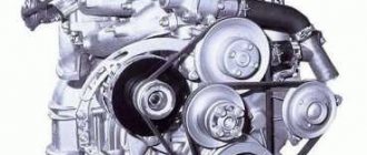
The engines produced for these VAZ models differ only in volume, but have no structural differences. They are equipped with both contact and non-contact ignition systems.
The first case is when the contacts are opened mechanically, and in the second case a Hall sensor is used, with the help of which the moment a spark is supplied to the combustion chamber is determined.
SZ scheme
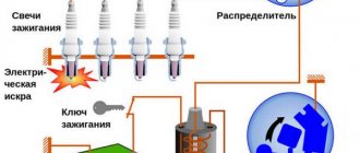
The ignition system used on the VAZ 2109 includes the following components:
- Switch;
- Candles;
- Distributor sensor;
- Ignition coils;
- Switch;
- Locking device. It does not allow the starter to turn on until the ignition is completely turned off;
- Locking and anti-theft device;
- Hall Sensor;
- The sensor-distributor roller, which is located horizontally and receives torque from the camshaft;
- System of spontaneous ignition shutdown, which is activated after 2-8 seconds;
- Switched current equalization system, which is required when the network voltage changes within the range of 6-18V;
- The system built into the switch, which regulates the time of energy accumulation in the coil, limits the current strength at low motor operating frequencies.
The ignition system operates with a voltage of up to 26 kV, the spark charge has a duration of 1.6-2.0 milliseconds, and the energy released during this time is 35-50 MJ.
Contact ignition
The system consists of: high voltage coil, contact group, distributor, distributor cover, vacuum and centrifugal regulators, resistance, spark plugs and wires.
- The system works as follows. When the piston is at TDC, the coil windings open.
- At this time, high voltage is directed from the distributor cover through the wires to the spark plugs, with the help of which a spark appears in the combustion chamber and, accordingly, the working mixture ignites.
As the engine speed increases, the advance angle undergoes changes, and the centrifugal regulator changes it to the required level.
In turn, the vacuum regulator changes the angle in proportion to the vacuum in the intake manifold. Thanks to this, the engine operates with the required power at any crankshaft speed.
Types of SZ on VAZ cars
Before checking the VAZ ignition coil, let's understand the types of SZ.
- Contact system. This type is considered one of the oldest; compared to more modern options, it has many disadvantages. As a rule, most often in such systems the circuit breaker and distributor fail. In addition, over time, the SZ contacts may burn and stick, as a result of which the operation of the power unit may be disrupted.
- Contactless ignition on a VAZ or BSZ is a more modern option made by the developers to ensure higher reliability. In this case, the design eliminates the use of a breaker; instead, a contactless sensor is used. Today, BSZ is used on many cars; quite often VAZ owners install it instead of contact SZ. In general, units of this type require virtually no monitoring, since there are no rubbing elements in such systems. The use of BSZ allows you to achieve optimal engine performance and better combustion of the air mixture.
- Electronic ignition is considered one of the most advanced options. Electronic ignition also almost completely eliminates the use of friction components. In addition, such a system is equipped with various controllers, as well as a control unit. Controllers are used so that the electronic ignition can record the operating parameters of the internal combustion engine, and this, in turn, is necessary for the timely supply of a spark. This SZ ensures the most optimal and correct operation of the power unit. But its main advantage is its efficiency (the author of the video is Roman Romanov).
Signs of incorrect ignition on VAZ cars
Setting the ignition timing on a vehicle is necessary if the internal combustion engine is being repaired or the distributor is being dismantled. Also, during operation, it undergoes wear and tear, like any other engine systems, and accordingly the following signs of malfunction may appear:
- The motor does not start or has interruptions in operation. Provided that the combustible mixture is supplied correctly, the malfunction may be an incorrect setting of the advance angle, slipping or stretching of the timing chain.
- Poor acceleration and inelasticity of the engine. This means that the combustible mixture is not ignited at the required piston stroke position, which leads to a deterioration in the efficiency of the internal combustion engine.
- High gas consumption. This effect occurs under conditions of late ignition. Part of the combustible mixture does not have time to burn and flies out into the exhaust manifold. In such cases, you can hear characteristic popping noises in the exhaust while the engine is running.
Hard work of the internal combustion engine. This occurs under conditions of early ignition, when the working mixture ignites when the piston position has not reached top dead center.
In such cases, you can hear a characteristic ringing sound in the engine. Such symptoms can lead to burnt out exhaust valves.
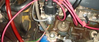
A few words about the contact group
To increase the secondary voltage, and, therefore, reduce the burning of this group, it is necessary to connect a capacitor. You can see it in the lower part of the distributor housing on any car equipped with a classic ignition system.
When the contacts begin to open, and the gap in them is very small, at this moment a small but very strong spark can form between them. It is at this time that the capacitor is charged. Once the contacts are completely open, the risk of sparking is minimal and the capacitor begins the discharge process. Current is released into the ignition coil, into its primary winding.
This creates a current pulse, which allows the magnetic flux to disappear, and most importantly, with its help you can achieve a higher voltage on the secondary winding. It is worth noting that the capacitance of the capacitor may vary in different cars. As a rule, it is in the range of 0.17..0.35 µF. If we talk about VAZ cars of the classic series, then the capacitance of this capacitor fluctuates in the range of 0.2..0.25 µF.
If you increase or decrease the value of the capacitance of this capacitor, this will inevitably lead to a voltage drop on the secondary winding. During the charge and discharge of the capacitor in the secondary winding, the voltage is about 5 kV (maximum).
Instructions
There are several popular methods for setting the ignition angle on VAZ cars.
Installation with strobe
In this option, you do not need to remove the distributor and valve cover, and the installation time will not exceed five minutes.
- Loosen the distributor nut, noting its initial placement in advance.
- We connect the negative wire of the strobe to the ground of the car, and the “plus” wire to the coil and a special clamp to the wire of the first cylinder.
- The light beam, strictly directed at the pulley, will accurately show the optimal location of the distributor.
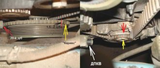
By gradually turning the distributor, it is necessary to correctly align the marks on the crankshaft pulley and the marks on the front timing cover. We fix the distributor nut.
Installation by marks
The mark on the pulley number 4 is combined with the mark on the front cover. The values of the marks are as follows: 1-100 degrees, 2-50, 3-00. When installing the ignition. when the engine is running on 92 gasoline, the mark for 0 degrees is selected.
We set the ignition to the light bulb
Before starting the installation, you need to take a 12-volt light bulb and solder two wires to it. Then, using a wrench, turn the crankshaft to the TDC position of the piston of the 1st cylinder.
- We place the marks opposite each other on the crankshaft pulley and the front cover.
- Remove the distributor cover so that the distributor is in the position of the first cylinder.
- We attach one of the wires from the light bulb to the ground of the car, and the second to the low-voltage wire inside the distributor.
- Turn on the ignition. If the ignition is installed correctly, the light will not light up.
- Otherwise, we install the distributor in such a position that the light does not light (i.e., the contacts are open).
When using this installation method, the light bulb can be replaced with a multimeter.
Installation by ear
Warm up the engine to operating temperature. Then loosen the nut securing the distributor. Slowly turn the distributor to the right and left until the engine operates optimally at idle without unnecessary knocking or detonation. Tighten the distributor fastening nut.
Ignition system of VAZ2101-VAZ2103 cars, ignition distributorDevice
The ignition system includes: an ignition coil, an ignition distributor, low and high voltage wires and spark plugs.
The ignition order in the cylinders is 1-3-4-2. The installation primary ignition timing is 5-7° (3-5° for BA3-2103 vehicles produced since November 1973).
The ignition system circuit consists of two circuits (Fig. 299): 1
the low voltage or primary circuit, which includes the electrical source, ignition switch, capacitor, ignition coil primary, and distributor breaker;
high voltage circuit or secondary circuit, which includes the secondary winding of the ignition coil, rotor with built-in suppression resistor, distributor cap with central contact carbon, high voltage wires and spark plugs.
Distributor. Until 1973, the P125 ignition distributor was used on VAZ-2101 and VAZ-2102 cars. In 1973, a unified ignition distributor P125 began to be used, intended for installation on VAZ-2101, VAZ-2102 and VAZ-2103 cars. It differed from the previously installed one in the characteristics of the ignition timing regulator and the dimensions of the roller shank (Fig. 300.6). Since 1974, the BA3-2103 car has been equipped with the P125-B ignition distributor, and all other cars have the same, non-unified P125 ignition distributor. The P125-B ignition distributor has the same characteristics of the ignition timing regulator as the unified P125, but the dimensions of the roller shank are different (Fig. 300, c).
Rice. 299. Electrical diagram of the ignition system: 1 - battery; 2 - generator; 3 — ignition switch; 4 — ignition coil; 5 — spark plugs; 6 - breaker; 7 - distributor; 8 - capacitor Designation of wire color. Core - brown; Ch - black; GC - blue with a black stripe
Rice. 300. Shafts of the ignition distributor rollers - P125; b - unified P125 c - P12c "
The ignition distribution includes the following devices:
low voltage circuit breaker, octane corrector, centrifugal ignition timing regulator, capacitor, high voltage current distributor.
The ignition distributor is installed in the upper left front part of the engine, secured with a special plate 6 (Fig. 301), which presses the housing flange to the upper plane of the cylinder block, and is driven into rotation by the oil pump drive gear, which has a splined hole into which the distributor shaft shank is inserted. .
A cermet bushing 19 is pressed into housing 4 (Fig. 302), in which roller 1 rotates. The bushing is lubricated through a felt wick (filt) from oiler 29. The housing is closed on top with a plastic cover 16, under which the main parts of the ignition distributor are located.
The breaker serves to interrupt the current in the low voltage circuit and consists of a cam 8 with four protrusions and a stand 22 with contacts 27, which the cam opens when rotating. The cam is lubricated with felt felt 20 soaked in oil. An axis is riveted to the stand, on which a lever 24 with a contact is mounted on a textolite sleeve, pressed by a leaf spring 23 to the contact of the stand. A textolite block is attached to the lever, which is in contact with the cam protrusions.
The stand 22 is secured with two screws 21 and 25 on the movable plate 7 of the breaker. The lower end of the lever axis fits into the hole of the movable plate, so when adjusting the gap between the contacts, the stand can be rotated around the axis by first loosening the fastening screws.
The octane corrector allows you to manually adjust the ignition timing within small limits. This may be required after refueling the car, since gasoline of the same brand, but manufactured at different factories, may differ slightly in their
characteristics. The octane corrector rod 5 is attached at one end to the axis 6, riveted to the movable plate, and at the other end to the eccentric axis 18. There are divisions on the eccentric. Each division corresponds to a change in the ignition timing by G along the crankshaft. When the eccentric rotates, the rod 5 moves, turning the movable plate with the stand 22 relative to the distributor shaft.
If you rotate the eccentric in the direction of the arrow <+>, the ignition timing will increase, and in the direction of the arrow <-> it will decrease. In the position of the normal initial ignition timing (5-7° or 3-5° for BA3-2103 vehicles produced since November 1973), the adjustment mark must coincide with the zero of the eccentric scale.
The centrifugal ignition timing regulator automatically changes the ignition timing depending on the engine speed. This is ensured by the fact that the cam bushing 2 (Fig. 303) is connected to the roller 1 not rigidly, but through weights 6 and springs 4 and can be rotated by the weights by 15-15.5° relative to the roller.
When the engine is running, the weights diverge under the action of centrifugal forces, rest their protrusions on plate 5 and, overcoming the resistance of the springs, rotate plate 3 (and therefore cam 2) clockwise relative to the distributor shaft, increasing the ignition timing.
Rice. 301. General view of the ignition distributor installed on the engine: 1 - cover; 2 — octane corrector; 3 - hole for lubrication; 4 - capacitor; 5 — plate fastening nut; 6 — distributor mounting plate
Rice. 302. Ignition distributor P125: 1 - roller; 2 - oil deflector coupling; 3 — hairpin; 4 — body; 5 - traction; 6 - axis; 7 — movable breaker plate; 8 — breaker cam; 9 — driven plate; 10 - drive plate; N - rotor; 12 - central carbon electrode; 13 — output of the central electrode; 14 - resistor; 15 - side electrode; 16 - cover; 17 — weight; 18 — eccentric octane corrector; 19 — roller bushing; 20 - felt; 21 and 25 — screws for fastening the rack with the breaker contacts; 22 _ stand with breaker contacts; 23 — lever spring; 24 — lever; 26 — groove for adjusting the position of the stand; 27 — breaker contacts; 28 — nut securing the tip of the low voltage wire; 29 — roller oiler
Rice. 303. Operation of the ignition timing regulator: a - at idle speed of the engine; b - at maximum roller rotation speed
Rice. 304. Ignition coil B117-A: 1 - external magnetic circuit; 2 and 5 - gaskets; 3 - secondary winding: 4 - primary winding; 6 - output of the end of the primary winding; 7 - cover; 8 - high voltage output; 9 - contact screw; 10 — output <+B>; 11 — body; 12- spring; 13 — coil mounting bracket; 14 - core; 15 - insulator
The higher the rotation speed of the roller, the more the weights diverge to the sides, turning cam 2 to a larger angle.
The springs tightening the plates 5 and 3 differ in the number of turns, wire diameter and length. The spring, which has greater elasticity, is installed with low tension and prevents the weights from moving apart at low engine speeds. The regulator comes into operation at an engine crankshaft speed of 1000 rpm, when the centrifugal force of the weights begins to overcome the resistance of this spring. At higher crankshaft speeds, a second spring comes into action, more rigid, mounted freely on the axles. This provides the necessary change in the ignition timing at different engine speeds.
The distributor consists of a rotor 11 (see Fig. 302) and electrodes installed in a plastic cover 16. The plastic rotor is secured with two screws to the plate 9 of the ignition timing regulator. The rotor is fixed in a certain position. This is provided by square and round holes in plate 9, into which rotor protrusions of the same cross-section fit. The central and outer contacts are riveted on the rotor, between which in the recess there is a resistor 14 with a resistance of 5000-6000 Ohms, designed to suppress radio interference.
A spring-loaded carbon electrode 12 rests against the central contact of the rotor, transmitting high-voltage pulses from the ignition coil to the rotor. When the rotor rotates, these pulses are transmitted from the outer contact of the rotor to the side electrodes 15 embedded in the cover and, further, to the spark plugs. Capacitor 4 (see Fig. 301) with a capacity of 0.20-0.25 μF, mounted on the housing, is designed to reduce sparking between the contacts of the breaker and to increase e. e.e., induced in the secondary winding of the ignition coil.
The ignition coil is used to convert an intermittent low voltage current (12V) into a high voltage current (11-20 kV) to break down the air gap between the spark plug electrodes. It is installed in the engine compartment and is attached to two bolts welded to the bottom of the left wheel mudguard. On cars, an ignition coil of type B117-A (Fig. 304) of domestic production or B 117 produced by NRB can be installed. The characteristics of these coils are the same, and the differences concern only small structural elements. The coil is a transformer on an iron core 14 and an annular outer magnetic core 1. The core is located in a cardboard frame on which a secondary winding 3 is wound, and on top of it a primary winding 4. The windings, together with the magnetic core and core, are placed in a seamless aluminum housing 11 and filled with transformer oil .
The reel body is closed on top with a plastic cover 7, the collar of which is rolled into the body and sealed with a gasket 5 made of oil- and petrol-resistant rubber. The ends of the winding wires are connected to the terminals embedded in the cover. The beginning of the primary and the end of the secondary windings are soldered to pin 10, marked < + B>, and the end of the primary winding is soldered to pin 6 (without marking). The beginning of the secondary winding is connected to the core plates and then through spring 12 and screw 9 to terminal 8 of the high voltage wire. Screw 9 is screwed into the cover and sealed with a rubber washer.
Read more about repair and maintenance of VAZ cars...
Contactless ignition system for VAZ
When installing such an ignition, the engine starts better when cold, there is no need to adjust the gap on the contacts, the spark will be more powerful, the service life of the spark plugs will increase and, moreover, it is more reliable in contrast to the contact one.
- As in the case of contact ignition, we align the marks and the piston of the first cylinder to the TDC position.
- We remove the old contact distributor, having first removed the negative terminal of the battery. We install contactless.
- Next, using a strobe light, we set the required ignition timing.
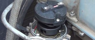
Contactless distributor
The VAZ 2101 non-contact type ignition distributor is practically no different from the contact type, except that a Hall sensor is used instead of a mechanical breaker. This mechanism is modern and more reliable, since there is no need to constantly adjust the distance between the contacts. Structurally, the sensor is located on the distributor shaft and is made in the form of a permanent magnet with a screen and slots in it. When the shaft rotates, the screen holes pass through the magnet groove, which leads to changes in its field. Using the sensor, the distributor shaft revolutions are read, after which the information is sent to a switch that converts the signal into current.
Diagnostics
The contactless ignition distributor is checked in the same way as the contact one, with the exception of the contacts themselves. Instead, attention is paid to the Hall sensor. If problems arise with it, the engine begins to work unstably, which manifests itself in the form of floating idle speed, problematic starting, and also twitching during acceleration. If the sensor fails completely, the engine will not be able to start. At the same time, problems with this element arise infrequently. A clear sign of a Hall sensor failure is the absence of a spark at the central contact of the ignition coil, so not a single spark plug will work.
You can check the part by replacing it with a known good one or by connecting a voltmeter to the output of the element. If it turns out to be working, the multimeter will show 0.4–11 V.
Many years ago, I installed a contactless distributor on my car, after which I practically forgot what a distributor was and problems with ignition, since there was no longer a need to periodically clean the contacts from burning and adjust the gap. It is necessary to adjust the ignition only if any repair work is carried out on the engine, which happens quite rarely. As for the Hall sensor, during the entire operation of the contactless device (about 10 years) it has never changed.