Possible reasons for failure of the ignition module
Before repairing the main part in the car’s ignition system, you need to understand the nature of the problem. To do this, the consumer must be aware of the signs of a malfunction, as well as the causes of the breakdown.
The main reasons for device failure
Causes of problems:
- The ignition system uses spark plugs that do not match the vehicle parameters. They may not have the gap specified by the manufacturer. Also, the spark plugs themselves may not be working or dirty; this can be determined by visual diagnostics. If there are traces of carbon deposits on the devices, they must be removed.
- Malfunctions in the operation of the MH can arise as a result of frequent spark checks. At the time of diagnosis, a high load is placed on the device. If it appears frequently, it will lead to equipment failure or incorrect operation.
- The ignition module in the VAZ 2114 operates with the high-voltage cables disconnected. This also leads to device failure. The products themselves may be damaged, which affects the functioning of the engine as a whole.
- The device operates under severe vibration conditions. Their impact may be due to poor quality fixation of the module in the seat. As a result of vibrations, the factory soldering inside the equipment structure is damaged. This leads to its incorrect operation.
- The contact inside the plug with the low-voltage cables is broken.
- Initial use of a defective device or module with poor build quality. This factory defect can only be eliminated by replacing the mechanism; repairing the equipment is pointless.
- Moisture getting inside the case. This problem is unlikely, but exposure of the device to liquid may cause it to short out and break.
Signs of coil malfunction
The main symptoms of a malfunction in the VAZ 2114 ignition module:
- Difficulties arise when trying to start the engine. Starting the car engine may be difficult due to the fact that there is no spark on a spark plug or several.
- When idling or parking with the internal combustion engine running, the speed of the power unit floats. Their change is not associated with pressing the gas pedal and other third-party factors. This happens randomly.
- There are dips in the power of the car's engine. This is especially felt when driving uphill or sharp acceleration. Problems can also occur when driving on a flat road.
- Several cylinders stopped working. Usually these devices operate in pairs, so elements 1-4 or 2-3 could fail. Non-working cylinders may be indicated by “triple movement” of the engine.
- A “Check Engine” warning light appeared on the dashboard.
If the ignition module malfunctions, problems will appear not only in engine operation, but also when starting it.
The “Simple Opinion” channel, using the Lada Priora car as an example, spoke in detail about the symptoms that appear in the operation of the ignition modules.
Consequences of incorrectly setting timing marks
If the ignition is set incorrectly, the following negative aspects are possible:
- If the engine has 16 valves, then they become deformed or bent during operation, accumulating damage.
- The previous problem causes damage to the cylinder head.
- The guide bushings may also become unusable.
- Cracks may appear in other engine components.
Crack in the cylinder block
- The motor overheats.
- The engine piston mechanism can burn out.
- Oil residue may appear on the spark plugs.
Oil deposits on spark plugs
- The fuel mixture loses its ignition moment.
Note! If the engine has 8 valves, then the consequences are not so critical - traction disappears, the belt quickly wears out and breaks.
After repairs, the following factors most often indicate an incorrectly set ignition:
- The car accelerates worse.
- Frequent overheating of the motor.
- The craving became much worse.
How to check the malfunction of the VAZ 2114 ignition module on your own?
The easiest way to check the device without removing it is to diagnose it at the moment the power unit is tripped. When the motor begins to operate unstably, it is necessary to disconnect the connector elements from each component of the module one by one. If the connector is disconnected from a functioning device, the operation of the engine will change. Dips will appear, and the unstable operation of the unit will increase. When the non-working element of the MH is disconnected, the motor will operate in the same way.
There is another simple diagnostic method, its principle is as follows:
- You will need an assistant to check. The spark plug is removed from the seat. The high-voltage cable is disconnected from the device.
- Then the disconnected wire is connected to a spark plug, which is applied to the body of the power unit.
- The machine motor is starting, you need to make sure that a spark hits the spark plug. If it passes, a blue light will appear between the device and the surface of the power unit, its formation is accompanied by a crackling sound. If there is no spark, then the spark plugs, high-voltage cable and module must be diagnosed.
Ignition coil breakdown
The term breakdown of an ignition coil or spark plug tip means a breakdown in the weakest point of the housing or wire insulation due to a decrease in resistance, occurring in short periods of time. This is mechanical damage that leads to the appearance of cracks or melting. On the surface of the case, the breakdown site appears as black, burnt-out dots, longitudinal tracks or white cracks. Such spark piercing areas are especially dangerous in humid weather. This malfunction leads not only to failure of the mixture to ignite, but also to complete failure of the ignition module.
Often such places are not difficult to notice visually, but sometimes it is necessary to check the ignition coil, not with a multimeter or oscilloscope, but with a simple device made of two wires. When a damaged area is identified, the part is usually completely replaced, although sometimes it is possible to delay the replacement using electrical tape, sealant or epoxy glue.
For what malfunctions is it possible to repair the device?
Due to the fact that the ignition module by design includes a connection of two coils, it is difficult to repair. If there is a break or breakdown, as well as melting of the turns, the problem can be solved by replacing the device. This applies to any damage that appears inside the coils. The only option to correct the situation without replacing the device is to repair the damage to the solder joint.
Ignition module repair process
The repair procedure is carried out after preparing all tools and materials:
- a set of socket wrenches, you will need a tool for 10, 13 and 17;
- hexagon 5;
- flat head screwdriver;
- soldering iron with aluminum and flux;
- nail polish;
- multi-core conductors.
Restoring the ignition module operation is done as follows:
- The key is installed in the switch. The engine starts. Then you need to move the contact elements on the module to make sure they are not working.
- The power unit stops. The module is being removed.
- The device body is cleaned from dust. To disassemble, you need to open the case; this is done by prying it off with a screwdriver. Inside the device there is a board on which there is a silicone film; you need to get rid of it.
- Aluminum is removed from high-voltage contact elements. Old wires are removed.
- The next step will be soldering new conductors to the circuit. To do this, the surface of the collector device is cleaned from traces of plaque. Then the board must be installed on an electric stove and heated to approximately 200 degrees. As the temperature increases, a slight burning smell may be heard. This is not a problem for the circuit; heating it will simplify the soldering procedure.
- Then soldering is done. Using a soldering iron, flux and aluminum, the ends of the conductors must be connected to the ignition module. All contact elements of the conductors that are connected to the circuit must be treated with nail polish.
- Then the device is assembled in the reverse order and installed in the seat. After installation, the power unit starts up. If the repair solves the problem, then using a sealant, the device is fixed in place.
- If a transistor or switching device fails, then these components cannot be repaired, but they can be replaced. To do this, the parts are removed from the board and replaced with new ones.
Search
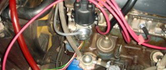
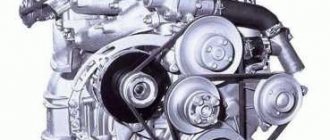
The 2nd Samara was the first front-wheel drive car from VAZ with an injection system at the beginning. The first copies of the VAZ-2114 were still sold with an eight-pole engine and a contactless ignition system, and subsequent engines already had a 100% electrical system with the same 8 valves. Before installing the ignition, it is necessary to find out what system is installed on the engine, which we will do at the moment.
It is quite simple to calculate the type of ignition system on a VAZ-2114 - if a switch is installed, an analogue of a contact ignition ignition switch, this means that the system is contactless, but with a distributor-distributor. In this case, the ignition timing is set by turning the distributor to a certain degree. . The accuracy of the adjustment depends on the experience of the technician, as well as on the equipment used. However, such a system will allow you to flexibly and accurately adjust the ignition using a strobe light.
Most engines that were installed on the 2nd Samara and the tenth VAZ have a non-contact electric ignition system. There is no distributor, since the ignition timing is controlled automatically in real time and only with the help of the engine control system, electronics. The system does not require maintenance, and its diagram is shown in the photo below.
As can be seen from the diagram, which is implemented in eight-valve injectors, for the correct operation of the ignition system of the electric engine control unit, it is necessary to supply the appropriate information from the sensors. The main sensor of the system is the crankshaft position sensor . It is located on the left at the exit of the cylinder block next to the alternator drive pulley when looking at the end of the crankshaft.
Replacing the timing belt on the 8 cl engine VAZ 2108,2109,2110,2111,2113,2114,2115
Crankshaft position sensor
Replacing the ignition module of a VAZ 2114
If repairing the MZ VAZ 2114 is impractical or impossible, then the problem with the operation of the device can be solved by replacing it.
The equipment needs to be changed only when the battery is disconnected. Otherwise, there is a risk of short circuits and failure of other electrical appliances.
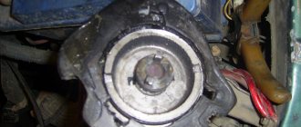
How to remove the ignition module of a VAZ 2114?
The dismantling procedure is performed as follows:
- First, the on-board network is de-energized; to do this, loosen the negative clamp on the battery with a wrench.
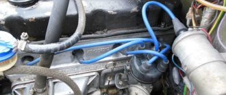
- Then a search for MH is performed in the engine compartment. You can find the device by four high-voltage wires that go from the spark plugs directly to the equipment. These cables are disconnected from the MH.
- Then the connector with conductors is disconnected from the device. It is necessary to disconnect the fixing fastener located on the ignition module housing.
- The MZ itself is secured to the bracket thanks to three nuts. You need to unscrew them using a key.
- After dismantling the fasteners, the device located on three studs is removed.
Connecting a new device
The equipment installation procedure is performed in reverse order; during installation, the following nuances must be taken into account:
- After installing the ignition module, you need to look at its surface. It is marked with numbers - 1, 2, 3 and 4. These symbols indicate the numbers of the cylinders to which the MZ should be connected.
- To properly connect the device, you need to look at the ends of the high-voltage cables. They are also marked with the same numbers. This is done in order to simplify the procedure for connecting the MH to the cables.
Connection diagram
The device must be connected in accordance with the diagram given in this section.
Connection diagram for MZ on VAZ 2114
How to check the device after connection?
Diagnostics of the operation of the new VAZ 2114 ignition module can only be performed using a special device - a high-voltage arrester.
You can find it in almost any auto store. Using the equipment, you can diagnose the module, as well as high-voltage cables, for the presence of a spark. To check, you need to connect the device to the device and use its operating instructions.
How to set the ignition correctly
Setting marks on an injection engine not only corrects the ignition timing, but also coordinates the operation of the gas distribution mechanism and the injection system.
Therefore, by correctly setting the marks on the VAZ-2114 engine, we fully regulate the operation of all its systems.
The adjustment should begin with preparation - placing the car on a level surface and tightening the handbrake. You can use several methods, but we will offer one of the optimal ones, without any special acrobatic tricks, which are not particularly desirable, especially in winter.
The work is carried out in the following order:
- For ease of work, it is recommended to remove the right front wheel. It will provide full access to the timing mechanism drive, and this way you can set the marks more accurately and quickly. In addition, you must first remove the plastic timing belt cover from under the hood.
Removed the wheel and plastic protection
Loosening or dismantling the timing belt on a VAZ-2114 (8 valves)
- Before setting the ignition to the marks or replacing the timing belt, it is necessary to loosen or completely remove the generator drive belt. If the timing belt is normal, then there is no need to change it, then there is no need to dismantle the alternator belt.
- To accurately set and check the position of the crankshaft, it is necessary to remove the generator drive pulley itself. This is done with a 19mm head. If it doesn’t work the first time, you can rest the knob against the lower arm of the front suspension and turn the crankshaft with the starter. The bolt will definitely break.
- Now you need to loosen the timing belt tension roller. We do this using a regular open-end wrench size 13.
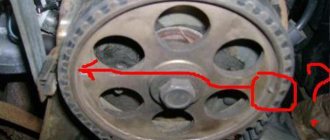
- We control the position of the camshaft drive gear. There is a mark on it that should correspond to the mark on the timing belt. We bring the gear to the mark.
- We check the bottom mark on the crankshaft, or more precisely, on the gear, which is rigidly fixed on it. The mark on the gear should match the mark on the top of the cylinder block boss.
Checking the set ignition
- We check that the mark on the flywheel matches the mark on the gearbox housing. To do this, remove the hatch in the gearbox; the mark on the flywheel should be visible, which in this position of the shaft must coincide with the mark on the crankcase.
Checking the marks on the hatch
Belt is on and tight
What should I do if the problem remains after replacing the module?
If, after performing the repair, problems in the operation of the MH remain, then there is a possibility that the cause of the problem was not in the module. It is necessary to diagnose the remaining elements of the ignition system.
Spark plugs and ignition system
Features of checking spark plugs and other components:
- Before dismantling the devices, it is necessary to disconnect the ends of the high-voltage cables. Their condition is checked for damage. Defects in the tips often lead to malfunctions in the spark plugs. If there is damage, the wires are replaced. It is also necessary to assess the condition of the “high-voltage workers” themselves. They are not allowed to have any defects or damage to the insulation.
- After disconnecting the tips, the spark plugs are dismantled and a special spark plug wrench is used to unscrew them.
- After dismantling, the condition of the devices is assessed. The color of the parts must be brown; carbon deposits and soot on the electrodes are not allowed. If there are uncharacteristic marks, the devices are cleaned using a metal brush or fine-grained sandpaper. For a better effect, the electrodes of the candles can be heated on the stove.
- The condition of the gap between the part and the electrode element is checked. If it is too large, this indicates that the device is not working correctly. The spark plugs will need to be replaced.
Marks and direct adjustment
When the preparation is completed and the car is ready to work with it, you can begin to set the ignition marks of the VAZ 2114. The task of the procedure is to check the synchronism of the system (correlation of the camshaft, crankshaft and injection timing), with some nuances for the electronic system.
For electronic ignition systems, there is a small nuance - the need to check the distance from the master disk to the sensor. Normally, this distance should not exceed 0.7 mm, but should not be less than 0.5 mm. You can use a valve feeler gauge to check.
The further procedure for the electronic ignition system is as follows:
- We look into the mark hatch and align the gearbox housing mark with the flywheel mark by turning the crankshaft.
- We find the mark on the oil pump pulley and make sure it matches the tide of the cylinder block.
- Align the camshaft pulley mark with the head boss.
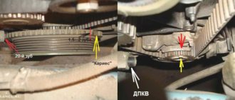
- The work is completed, to check the correct setting, check that the gap on the disk coincides with the tide of the cylinder block, and the twentieth tooth with the crankshaft position sensor. If everything matches, you have successfully completed the task.
Examination
Checking the VAZ 2114 ignition module is carried out as follows.
First of all, you need to check the block of wires that go to it. To do this, disconnect the block of wires, take a tester and connect one of its probes to the block, and connect the other to engine ground. Now look at the tester readings: the voltage should be around 12V. If there is no voltage, then you need to check the fuse. Then take a 12V test light and connect it to pins A and B. Turn on the starter and watch: the lamp should blink, if it doesn’t blink, therefore, there is an open circuit on pin A. Perform a similar operation with pin B. So, how to check the ignition module VAZ 2114, 2115 (8 valve injector)? Today there are several verification methods. 1) The first method is to replace the unit with a known working one. Everything is simple here: take it from the donor car and replace it. But there are certain disadvantages here: - there may not be a donor car, buying a new unit does not suit our task - it will not fit any car. Not everything is so simple here: old Samaras with a 1.5 liter engine are equipped with an ignition module. New cars are often equipped with ignition coils. In them, the switch is located in the ECU - therefore, the module is eliminated as unnecessary, leaving only the coil. — you need to make sure that the high-voltage wires are in good condition, otherwise there is a possibility that the unit will burn out. 2) The second method is the method of moving the unit. If at the moment of your impact the engine operation changes, then the problem is poor contact. This malfunction is common, so you can try to repair the unit yourself. If it cannot be repaired, then it must be replaced with a new one. 3) To check you need a tester. Using a tester, measure the resistance at the paired terminals between cylinders 2 and 3, as well as between cylinders 1 and 4. The resistance should vary around 5.4 kOhm and be the same.
The 2111 (1.5i) engine may have an ignition module or an ignition coil installed. The 11183 (1.6i) engine is equipped with ignition coils.
To perform the work of replacing the ignition coil, you will need a multimeter.
How to set the valve timing according to marks on a VAZ 2113-VAZ 2115?
1) As we said earlier, if you just need to set the marks, provided that your phases are set normally before removing the timing belt, for example, then all this is done easily and quickly, but if these marks do not match, then after This will force you to remove the timing belt and set all these marks, first we will explain how to set everything according to the marks and thereby you will make sure whether your valve timing is set normally or if there are deviations, let's get to work, first you will need to remove the cover that covers the mechanism Timing belt and after that put everything according to the marks, the cover is removed as follows, all the bolts that secure it are unscrewed (There are only three places where it is attached, in which one, see the photo below) and as soon as everything is unscrewed, remove the cover that closes the mechanism from the engine car.
2) Now we will give you two ways to align the marks with each other, the first is to drive the car in gear for a short distance, generally engage fourth gear and then push the car a little until the mark on the camshaft pulley matches with a mark on the rear cover (see photo 1), as soon as it matches, stop pushing the car and go to the far left part of the engine compartment (in the direction of the car if you look) and at the bottom find the clutch housing, remove the rubber plug from the housing that closes the hole (see photo 2) and after which you will have excellent access to the marks on the flywheel, this mark must necessarily coincide with the triangular cutout on the scale of the rear shield of the clutch housing (see photo 3), if the mark matches and the mark on the camshaft pulley, it means your valve timing is set normally, and by the way, in this position you can remove the timing belt, if that’s why you marked everything, but besides this method, you can use another one, that is, the second method is not rolling a car (It’s not always possible to roll a car) and in hanging the right front wheel, in general, take a jack and use it to lift the right wheel (look as the car moves), but you can do the left one, just if you lift the right one, you can do it in another way use (About the third method a little later), so when the wheel is raised, put the car in any gear and carefully turn the wheel by hand (It will be hard, but you still turn it) again until the mark on the camshaft pulley coincides with mark on the back cover, as soon as it matches, finish scrolling and check all the marks, there’s something else they wanted to tell you, besides two places where you can check the marks, there is also a third place (You don’t even have to look at it, you can check everything by the flywheel , but not always, if your flywheel, for example, is installed incorrectly, then the mark will also not coincide with that triangular cutout, so take this into account), so, the third place is the crankshaft pulley, there is a dot on it and on the oil pump cover too there is a cutout, they will have to coincide with each other when all the other marks also coincide (see. photo 4).
Note! We would like to explain a little about the third place where you can check the marks, firstly, this crankshaft pulley is located at the very bottom and in order to see it you will have to remove the front right wheel (For information on how to remove a wheel, read the article: “Replacing wheels on a car”) , but that’s not all, then the alternator belt will need to be removed and the alternator drive pulley (For information on how to do this, read the article: “Replacing the timing belt on a car”; in that article, read points 2 and 4 carefully), after that then you will have access to the third mark, by the way, that’s why almost no one looks at this mark, and everything is determined by the mark on the flywheel, but we also tell you that some people (inexperienced) can install the flywheel incorrectly (This very rarely happens) and therefore the marks will no longer match as they should!
3) Well, in conclusion, we’ll tell you about the third method of setting the phases according to the marks, it is done as follows, the right front wheel is also hung up (In the direction of the car) and it is removed, after removal, access to the bolt for securing the generator drive pulley opens (About this bolt, we already said in paragraph 4 in the article: “Replacing the timing belt on a car” to which the link is given above), you will need to turn this bolt clockwise with a wrench (it’s easiest with a socket wrench, but if you don’t have one, then with a socket head too everything can be done) again until all the marks coincide with each other.
Note! If you did everything correctly, but the marks still did not coincide with each other somewhere (For example, they coincided with each other on the camshaft pulley, but not with each other on the flywheel), then this indicates that your valve timing is broken and you will have to remove the timing belt (For information on how to remove it, see the very article to which the link is given above, it is also called: “Replacing the timing belt on a car”), after removal, all those pulleys will need to be turned that you need (Pulleys rotate, ways to rotate the crankshaft pulley we have already told you, and the camshaft pulley can be turned by hand along its axis, but just be careful, very careful, especially if your engine bends the valves, then when one of the pulleys rotates, the valves and pistons will meet each other and so that this meeting was not deplorable, do everything very carefully and wisely), turn it so that they coincide with the marks (By the way, if you are thinking about the flywheel, it will turn itself when you turn the crankshaft pulley and vice versa, if you suddenly decide to turn the crankshaft using the flywheel “This can be made thick and powerful with a screwdriver,” then the pulley itself will turn and stand in the position that you set on the flywheel, and if you set the flywheel according to the mark, then accordingly the crankshaft pulley will also be installed according to the mark, but how we said earlier, if the flywheel is not installed correctly, or even if the pulley is not installed correctly, then the marks on the pulley and on the flywheel will no longer coincide with each other), as soon as everything matches the marks, you can install the belt back after installation also check that the marks are positioned correctly, this is how you can correctly set the valve timing according to the marks!
Additional video clip: For more detailed information about where all these marks are located and how to correctly install the timing belt in its place so that all marks match, see the video clip below:
Note! Be sure to add to all this, study additional information that is shown in the video just below, namely, it says how to correctly tighten the bolts securing the cover that closes the timing mechanism, and it also says what will happen if these bolts are tightened incorrectly, in general, watch the video and you will understand everything yourself!
Withdrawal procedure
Release the lock and disconnect the wires from the ignition coil terminals.- Turn on the ignition and use a voltmeter to measure the voltage between terminal 15 and ground in the case of an ignition coil or between terminals C and D in the case of an ignition module on the wiring harness block. The voltage must be at least 12 volts. If there is no voltage or it is less than needed, then you need to check the charge of the battery, computer or power circuit. To check the ignition coil, you can replace it with a known good one.
- After taking measurements, turn off the ignition.
- Disconnect the high-voltage wires from the spark plugs.
- Using a 13mm wrench, unscrew the 2 bolts of the upper mounting of the coil bracket.
- Using a 17mm wrench, loosen the lower mounting bolt of the bracket and remove it together with the coil.
- Disconnect the high-voltage wires from the ignition coil
- Using a multimeter in ohmmeter mode, we measure the resistance between the central terminal 15 and the housing. The multimeter should show that there is no short circuit of the primary winding of the coil to ground. We sequentially measure the electrical resistance between the central terminal 15 and the outer terminals - 1a and 1b. The resistance of each of the primary windings of the coil should be about 0.5 ohms. When taking measurements, you need to take into account the device's own resistance.
- Using an ohmmeter, we measure the resistance between the high-voltage terminals of the coil 1 and 4, and then 2 and 3. The resistance of the windings should be about 5.4 kOhm.
- Using a 5mm hex wrench, unscrew the 4 screws securing the coil to the bracket and remove the coil.
Getting ready to adjust the ignition
In order to correctly set the ignition timing of the VAZ 2114 and carry out debugging, you need to prepare. The method described below does not require acrobatic agility from the owner and is quite feasible both in the uncomfortable and cramped environment of a garage and if the car enthusiast has a tummy.
IMPORTANT! Thorough preparation always speeds up the process of technical work significantly, regardless of what exactly needs to be repaired.
Preparation for debugging ignition marks is carried out as follows:
- The car is placed on a flat surface and placed on the handbrake.
- The second step is to remove the front right wheel, which will subsequently allow you to gain access to the gas distribution mechanism itself, which will speed up the work, make it convenient and easy, for this: a. unscrew the fastenings of our wheel and place a wheel chock under the diagonally opposite wheel (rear left); b. We lift the car with a jack, twist the wheel mounts completely and remove it.
- Finally, we need to remove the timing belt splash guard (if there is one, of course). By the way, you can not remove it entirely, but just unscrew the two lower fasteners, then it can be moved away without damaging it.
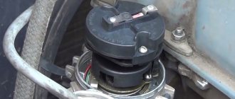
How to determine the slider position
The distributor slider in this video is installed on the 4th cylinder...
How do we determine which cylinder the distributor slider should be placed on? Of course, a spark jumps in this cylinder when the compression stroke ends.
In order to determine the (TDC) compression stroke, the spark plug is unscrewed and some car owners insert a plug made of paper or other material into the hole. Then rotate the engine shaft until the plug comes out of the spark plug hole.
You can do it much easier and faster using the method proposed by the author of this video...
We unscrew the spark plugs of the first and fourth cylinders, take a rubber hose, its outer diameter should fit tightly into the spark plug hole and insert it there. Then we blow into the hose with our mouth, first into the first cylinder, and then into the fourth.
In which cylinder is blowing tighter, then in this cylinder there is a compression stroke, that is, both valves of the cylinder are closed and a spark should jump here. For example, the fourth cylinder is blowing tighter and, accordingly, the slider on the distributor also “looks” at the fourth cylinder.