Installing a contactless ignition system on Izh Jupiter-5 is a fairly current topic. When setting up a BSZ on Izh Jupiter-5 BSZ, it is necessary to take into account a number of nuances that can significantly affect the operation of the equipment used.
What advantages open up to users who decide to install electronic ignition on the Izh Jupiter are described below.
Most modern motorcycles are not equipped with cams, that is, breakers. Why did the manufacturer consider them unnecessary for currently sold models? The answer is quite simple. This system is not very reliable.
Many parts used in the system are sources of trouble. The most common ones are listed below:
- The ignition gaps change their original position while driving a few days after adjustment;
- A spark occurs every once in a while, since the contacts regularly burn out;
- Capacitors are constantly damaged;
- Low spark power;
- If you add two or three volts to the battery, it is quite difficult to start it. Such ignition is the reason for constant repairs while driving.
Many people mistakenly believe that it is very difficult to implement BSZ Sovek on Izh Jupiter 5. As a rule, it takes more time to purchase the necessary spare parts than to install the BSZ on Izh. Of course, after implantation, performance changes significantly in the best direction.
This is noticeable at idle. The speed of their passage has noticeably increased and the unnatural twitching has disappeared. The characteristic knocking sounds of iron components in the crankcase and accompanying detonations also disappeared. The handling of the Jupiter 5 motorcycle will improve simultaneously with the time it takes to gain speed.
Guide to installing, configuring and adjusting electronic ignition on IZH Planet 5
Installation and configuration instructions
In IZH Planet motorcycles, be it version 3, 4 or 5, the ignition installation in accordance with the diagram must be carried out using the device that came with the motorcycle.
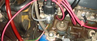
But since it is not so easy to find this device today, we will make do with improvised means. Non-contact ignition is configured by adjusting and setting the gap of the distributor contacts. An equally important nuance is the correct setting of the moment of sparking. If your IZH Planet 3 is equipped with a single-cylinder internal combustion engine with a G-36 M generator device, then in this case the procedure for setting the gap is carried out by turning the eccentric, marked in the diagram with the number 1. In this case, bolt 2 according to the diagram must be loosened, and the eccentric itself is turned or right or left.
Before setting the BSZ on products from the IZHMASH plant, the crankshaft must be turned. It rotates until the moment of greatest divergence of contacts occurs. It is in this position that the ignition of the IZH Planet 5 is adjusted - you need to ensure that the maximum gap on the contacts is around 0.35-0.45 mm.
In particular, setting the gaps between the contacts of the interrupting device should be done in the following order:
- First of all, the crankshaft is turned by the kick starter.
- One of the interrupting elements is set to the contact opening position. In this case, the bolt marked number 4 in the diagram must be loosened.
- Next, using the eccentric number 3, the gap is set; this figure should be from 0.4 to 0.6 mm. After this, the same actions are carried out with the second pair of contacts.
It should be noted that the entire procedure must be carried out with the candles unscrewed. When you place the dipstick in the corresponding hole for the spark plug in the right cylinder, you need to turn the crankshaft with the kick starter. You need to find the top dead center and having found it, you should make several marks on the dipstick - one of the marks should be placed at the level of the hole, and the other should be located slightly higher - about 2-3 mm.
In this position, the elements of the interrupter assembly, which is located on the lower surface, will begin to open. It should be noted that the procedure for setting the contact opening is done by turning the base, but to do this you need to loosen the bolts numbered 2 and 7. And when you can make the adjustment correctly, these screws will need to be tightened.
After the torque on the right cylinder has been set, the same procedure is performed in a similar way only on the left cylinder. In general, the situation is similar, only in this case it is not the lower, but the upper base that rotates, and in this case, bolts 1 and 7 should be loosened.
In this position, the elements of the interrupter assembly, which is located on the lower surface, will begin to open. It should be noted that the procedure for setting the contact opening is done by turning the base, but to do this you need to loosen the bolts numbered 2 and 7. And when you can make the adjustment correctly, these screws will need to be tightened.
Required Parts
In order for the ignition system to work correctly, a number of auxiliary parts are required. They are listed below:
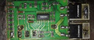
- Switch for BSZ VAZ cars. You should not choose exclusively from the low price segment. The Astro switch has a lot of positive reviews;
- Hall Sensor. The best option for Jupiter 5 is a similar manufacturer VAZ. By purchasing it in branded packaging, you protect yourself from counterfeits;
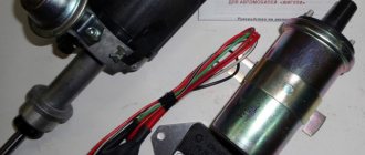
- Ignition coil with two terminals. You should choose between the gazelle engine number 406 or Oka with an electronic ignition system;
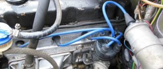
- A pair of silicone armor wires with rubber caps;
- The modulator is a butterfly-shaped plate made of iron.
System assembly and installation
The contacts in the breaker, the capacitor, the ignition bobbins and the armor wires, which are part of the previous ignition device, are probably eliminated. The switch should be installed in the glove compartment on the right, and the ignition coil directly under the tank. There are no gaps for fastening on the reel, which means it can be attached using a thick layer of adhesive tape. The standard bolt is also eliminated along with other parts.
In place of the bolt, install a pin of the specified size and put on a washer. Then, the rotor is tightened with a nut located at its end. The hall sensor is attached to the stator by any means. The basic rule when installing it is to set the optimal cross-sectional distance of the modulator and the ratio of the radius and line of symmetry.
When the hall sensor can be secured, we apply the modulator. It should fit into the hole made in the sensor. In most situations, there is a discrepancy between the sizes, so it is necessary to place washers on the stud. If you manage to maintain the required gap, it is recommended to install an engraver and tighten the modulator with a third-party nut.
Izh Jupiter-5 adjustable ignition
This article describes in detail the topic: Izh Jupiter-5 ignition adjustment, but let’s start a little with a preface.
If now motorcycles from foreign manufacturers predominate on the roads, then literally 20-30 years ago only domestic Izh “Jupiter” and “Planet” rode on our roads. 2 years difference in production, identical appearance, there are not many differences in them, but still Jupiter-5 wins due to its two-cylinder engine and its easier starting.
- Two-stroke, two-cylinder 347.6 engine;
- Air or liquid cooling system;
- Automatic clutch release mechanism;
- Drum brakes;
- 18 wheels;
- The steering wheel has a conventional instrument panel (speedometer, ignition lamp, etc.);
- Two shock absorbers. Setting up the ignition on Izh Jupiter 5 must be done in compliance with all rules. To do this, you need to know the exact algorithm of actions when carrying out this event. Therefore, in this article we will describe in detail how to set the ignition on Izh Jupiter-5.
Setting up contact ignition on Izh Jupiter - 5
Let's take a step-by-step look at how to set up contact ignition on this device:
- Align the piston of the desired cylinder: - insert a screwdriver into the cylinder - rotate the crankshaft while holding the screwdriver
- Take a ruler and place it next to the screwdriver.
- Rotate the crankshaft, holding the screwdriver down with your finger so that it is level. We find a dead point.
- Turn the crankshaft in the opposite direction (1.5-2 mm).
- A spark is generated when the cam opens, locate the two adjusting bolts.
- Take a light bulb with two contacts, connect one to ground, the other to the contact.
- Turn on the ignition switch.
- You need to find the moment when the light comes on (the moment it lights up, the start occurs), and when it goes out, the contact closes on the contrary.
- Turn off the ignition, do and adjust the same with the second cylinder
Ignition adjustment Izh Jupiter - 5
After all the adjustment manipulations are done, the turn comes for an operation called Izh Jupiter-5 - ignition adjustment.
It is better to produce from the following devices:
- Device K-25 - has an indicator head that fits into the holes for spark plugs or bushings and a knob with divisions from the tool
- Lamps 12 V, 2 W - with their help you can determine the moment of opening the necessary contacts of the breakers. The lamp must be connected to ground and the breaker terminal of the corresponding cylinder (for this, lamps with wires are used at the end), on which the ignition timing is adjusted.
Scooter ignition
Ignition from a scooter on the Izh Jupiter can work without a battery. Before setting it up, we need three details:
- Scooter switch;
- Ignition coil;
- Inductive original sensor (must have a single wire output).
The DC switch is powered from a 12 W network, also the on-board network of the motorcycle is 12 W, the switch has 4 wires, the first of which is plus, the second is minus, the third is to the coil, the fourth is to the inductive sensor. We reliably connect the negative wire from the switch to the negative wire from the motorcycle (ground), and connect the positive wire that goes to the standard coil to the positive wire of the switch.
Ignition coil connection:
- We connect the negative wire to the ground of the motorcycle;
- we stretch the second wire to the switch and connect it to the output under the coil
In order not to pull an additional wire to the inductive sensor through the entire engine, you can use the wire that connected the contact group and the standard ignition coil.
To do this, you need to take the wire from the switch that goes to the inductive sensor and connect it to the wire that went to the standard coil. Next, remove the capacitor and connect the inductive sensor
Particular attention must be paid to positioning the generator cover. It needs to be installed properly and not touch anything when rotating.
To do this, you need to shorten the cam a little and also make notches on it that prevent the modulator itself from turning. It is also worth observing the parameters of the gap between the modulator and the inductive sensor, which should be within 1-1.5 mm. When installing the ignition, you need to know that the spark strikes when the modulator leaves the sensor, and not at the input.
Once electronic ignition from a scooter is installed on a motorcycle, its performance will improve significantly. In particular, it will start much better (this will be especially noticeable when the battery charge level is low). Speed gain will also improve noticeably. The motorcycle will idle smoothly, which indicates proper engine operation.
Contactless ignition system for IZH Planet and IZH Jupiter motorcycles.
One of the options for tuning the Soviet motorcycle IZH Planet without reducing the engine's service life is to install electronic ignition to replace the standard cam ignition. Such a modification will provide a lot of useful and pleasant changes in the engine operation of your Izh. Electronic ignition provides timely and more powerful sparking, which makes the engine more responsive, reduces vibration levels, and reduces fuel consumption. BSZ equipment can be installed without removing the cam system, so that if the electronics fail, you can reconnect one wire and continue driving on the contact system. In addition, the engine on the BZS can be started even with a fairly low battery, and without particularly straining. The same electronic ignition system, with minor modifications, can be installed on a two-cylinder IZH Jupiter or on another motorcycle.
In order to make an electronic ignition system for an IZH motorcycle, we will need to purchase some components. Below we will look at the example of the IZH Planet model, although such a system will fit on the IZ Jupiter with minor differences:
1. Switch for electronic ignition from a VAZ 2108 car. 2. Hall sensor compatible with the switch. 3. Ignition coil with 2 outputs. (you can keep the original one) 4. Silicone hair armor wires.
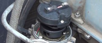
This is what an Electronic Ignition modulator on a motorcycle looks like.
The Hall sensor mount can be made from the cam mount. All excess is cut off, and the sensor is set on the washers at the desired height
It is important that the modulator flies freely inside and does not touch the edges of the sensor
I decided not to remove the original contact system, but the modulator and the cam mounting axis were in conflict. I had to file the axle and lift the modulator on the washer. Using the thickness of the washer we set the position of the modulator in the sensor gap. The switch can be installed anywhere. Many people hide them in the glove compartment. I needed the entire space of the glove compartment, and I attached it to it from the outside, next to the voltage regulator unit.
The fact that water and dirt gets on the sensor is not scary. The connector is almost sealed, but the wires should still be well insulated.
Electrical wiring The switch is connected to the Hall sensor and coil according to the diagram. The circuit is automotive, and we only need the part with the coil, switch and Hall sensor. The ignition coil output receives a positive from the ignition switch. In the diagram this is pin “B”, blue-red wire. The output of the “KP” coil in the standard contact system received a wire from the cam, which we disconnect, isolate, and leave nearby in case of failure of the electronic ignition system. The Hall sensor is connected with three wires, and it may be difficult to figure out where to connect pins 5 and 3 of the switch. The actual colors of the wires on the sensor do not match the diagram. If they are confused with each other, nothing will happen, but there will be no spark. When setting up the system, if there is no spark, this is the first possible reason for its absence.
The ignition coil remains original in my case, but you can use a Gazelle coil with two outputs. With such a coil, you can screw a second spark plug into the planet head instead of a decompressor, and by igniting the fuel in two places at once, we get better combustion of the fuel mixture.
It is better to use a silicone armored wire, although I also used regular copper wire. You can simply cut the wire with a knife at the base of the original candle holder and attach it to the coil. And screw it into the original cradle and ignition coil like a regular copper armored wire. I've been driving electronically for a year now, there haven't been any problems, I forgot what it means to set the ignition. Starts with half a kick. In terms of fuel consumption, it turns out to be a little more economical. The motorcycle is playful and responds well to the throttle. Install such a system for yourself and see its advantages.
Source
Final actions
You should put rubber caps on the armor wires, and insert the latter into the candlesticks or coil above. If you skip this step, the motorcycle will stall when riding in rainy weather, as moisture will get into the battery.
By inserting spark plugs into the tip, it will be possible to maintain excellent contact between the battery and the volume of the vehicle. Now you will need a pre-purchased set of wires. The switch, coil and hall sensor are connected by wiring. She needs to be isolated. Of the entire mass, only a common plus is required.
Motorcycle Izh Jupiter 5 - technical specifications and photos
Soviet motorcycles today are considered valuable transport, because back then they produced really high-quality and fast equipment. The Izh Jupiter 5 motorcycle is considered one of these legends of the USSR.
The Izhevsk plant produced several models, including Planet 5 and others. But Jupiter 5 was remembered primarily for its unpretentiousness on roads and maneuverability. With its small dimensions, the model was able to achieve low fuel consumption.
pros
- powerful engine;
- sharp at start;
- spare parts for Izh Jupiter 5 are inexpensive and available;
- soft suspension;
- low cost;
- has 2 cylinders.
Minuses
- weak front fork;
- requires good ignition settings;
- high fuel consumption;
- Motorcycles today require frequent repairs.
Technical characteristics of Izh Jupiter 5
The design of the motorcycle was created in such a way that in the end Izh could ride equally comfortably both on the highway and on uneven roads. Unlike its brother IZH Planet 5, this model had 2 cylinders, which means more power. Also, the owner of the motorcycle could start the engine more easily, which is explained by the absence of the leg returning when started.
Review
Classic transport has always been valued since the USSR, and 20 years ago Jupiter 5 was one of the best.
Today, most riders ride foreign fast motorcycles, but occasionally you can meet a former legend of the 80s and 90s.
In those years, only his brother Planet 5 competed with Jupiter, but he could not compare with the motorcycle in terms of characteristics. Their main difference was the difference in cylinders, and therefore power.
If we continue to compare these two competitors, we can highlight the fact that both models had almost the same data.
For example, they had one tubular frame, and a special subframe was installed to better secure the rear wheel.
In general, the entire design of Jupiter 5 was quite standard and simple, the engine was attached to the frame, the fuel tank was located above, and the headlight and dashboard were installed on the steering wheel.
There were also 2 exhaust pipes installed that ran through the entire motorcycle. Sometimes the pipes got hot and could cause a burn, but the manufacturer installed them below the footpegs to keep the passenger as safe as possible.
Even the first models of the Izh Jupiter 5 motorcycle had simple drum brakes with a mechanical drive, but subsequent modifications received a front disc brake with a hydraulic drive.
Motorcycle appearance
When the Jupiter 5 model came out, its design was already well-known, because it was inherited from the Jupiter 4 motorcycle. But soon the Izh Planet 5 appeared on sale, and the developers saw that they could borrow several design elements.
The first modification had a square-shaped dashboard, which consisted of several indicators, an ignition switch and a speedometer. But soon its appearance was redesigned, and instead of one dashboard there were two. On the first part they placed warning lamps, and on the second part they decided to put a speedometer.
The design of the fuel tank has also been slightly redesigned, with rubber pads on the knees and the shape of the tank itself has become slightly different. Accordingly, in the new modifications of the Moto Izh Jupiter 5, it received a different, longer seat that ended at the brake light. This innovation is still considered stylish and modern.
Being a workhorse, the motorcycle had a fairly sporty appearance and excellent top speed. With a power of 25 hp. the motorcycle could accelerate to 120 km/h.
This is a completely standard indicator, because another representative of the Dnepr could give a maximum speed of 110 km/h. In severe frosts down to 30 degrees, the unit started up perfectly, which cannot be said about the current new products.
Unfortunately, many owners complain of frequent engine breakdowns due to their long lifespan.
Price
Today, a motorcycle of this model is not so difficult to find; in Soviet times it was bought in large quantities, so today you just need to find out how much the Izh Jupiter 5 costs. Of course, the price depends on the condition, because over such a long period many parts could become faulty.
Even during the release of the Izh Jupiter 5 motorcycle, its price was quite high - 1,050 rubles. But this did not stop buyers; they wanted a comfortable and fast motorcycle, which was the best then. But still, compared to other motorcycles, this model had a relatively low price. For example, then new Ural motorcycles had a price of 1,870 rubles.
If you want to buy a legend of the USSR today, be prepared to pay 55,000 rubles for a new motorcycle. Yes, they are still being reliably produced. If this price is too high for you, buy a used model - its price ranges from 5 to 40 thousand rubles.
Improved ride quality
The icing on the cake, and in our case the final touch of tuning, is the improvement in driving performance. Some of the tuners approached this issue earlier when they sawed the frame of their motorcycle or raised the tail of a future crossover. For the rest, first of all, you should get rid of your original tires. Among its advantages, only wear resistance can be noted, for which you pay with your safety. It is both universal and useless. The lugs are practically useless; if they get into a mess, under normal conditions on the highway it is noisy, but relatively holds the road, turning into a killer on a wet highway.
Therefore, without hesitation, we throw it away and purchase road, cross or all-purpose tires, based on your requirements. The second point is the suspension. If everything is generally clear with the rear shock absorbers, they are extremely reliable and, in addition, have stiffness settings, then the front fork does not leak only for those who have chosen a different brand. There are two ways to get out of this situation. The first is to add thicker oil. The second is to carry out a complete overhaul of the feathers and replace all parts. Both options do not last long, so the most demanding owners simply change the fork to an imported one, while the rest endure all the shortcomings of their iron horse.
Setting the appropriate options
Setting up the BSZ on Izh Jupiter 5 also requires special attention. The ignition is turned on with the tachometer connected. After thirty seconds, indicators of 3000, 4000, 5000 rpm should appear on the device panel. If they are present, then the switch is working correctly.
In other cases, you should pay attention to previously grounded candles. We insert a screwdriver into the hall connector, and then pull it out
A spark should appear on the spark plugs. If it was not possible to cause a spark using the steps described above, then the reason for the incorrect operation is incorrect connections.
The setup looks like this. The dial indicator is unscrewed and the cylinder piston is adjusted. Having connected the voltmeter to the second and third connectors, you need to start rotating the modulator axis. After a jump from 7 to 0.1 volts is detected, the modulator must be secured with a nut. Usually the required advance angle is set.
The test run should be successful if you install the components yourself according to the instructions. Now you can use BSZ.
The main problem with the Izh Jupiter motorcycle engine is the standard contact ignition system. Any owner of Jupiter sooner or later faces the problem of failure of one of the cylinders due to a change in the gap in the contacts or failure of the capacitor. Adjustment helps, but usually not for long. This problem can be radically solved by installing a contactless ignition system on a motorcycle.
Single-channel BSZ.
There are probably many options for BSZ design, but we won’t consider them all. Let's focus on the simplest, and probably the most common option in our country. There is no motorcycle market or motorcycle store nearby where you can buy a factory-made BSZ, and there is no turner with a machine nearby either. We will proceed from this.
Minimum set for installation
But we can’t do without a minimum set, so before you start work, you need to stock up on the following components, which are sold in any auto shop or car market in our country:
1. Switch from VAZ 2108
2. Hall sensor from VAZ 2108
3. Set of wires for BSZ from VAZ 2107 (from distributor (Hall sensor) to switch)
4. Two-terminal ignition coil (from an Oka or Gazelle car with a ZMZ 406 engine)
5. Two automotive silicone high-voltage wires of the required length with caps for spark plugs (you can buy a kit for a VAZ and take it from there, you can simply find used wires, after first making sure they are working)
Next, in addition to the components, we will need a small flat piece of sheet steel 1-1.2 mm thick to make a modulator and a plate for the Hall sensor. I warn you right away that stainless steel or non-ferrous metals are not suitable for the manufacture of the modulator, since they are not magnetic materials. To make a plate for the Hall sensor, you can use any material of sufficient strength.
Tools you may need are a drill with drills, files, a chisel, a hammer and other tools that, as a rule, are found in any garage.
Rework process
We dismantle the old ignition system. We remove the plate with contacts, capacitors, ignition coils with high-voltage wires from the motorcycle. We install the switch in the right glove compartment.
We attach the ignition coil to the frame under the tank. We connect the wiring connector to the switch, connect the black ground wire from the connector to ground. We connect the wire from terminal No. 1 of the switch connector to one of the coil terminals. We connect the second terminal of the coil to the old wiring, to the wire to which “+12V” is supplied when the ignition is turned on. In the old wiring, this wire connected both ignition coils. From it we pull an additional “+12V” wire to the switch, which we connect to the 4th wire in the connector. We carefully isolate everything. We insert the wire with the connector to the Hall sensor into the cavity of the generator.
You can check the functionality of the system. We connect the Hall sensor to its connector, connect the high-voltage wires to the coil and to the spark plugs. We provide reliable weight to the candles. Turn on the ignition and pass a metal object (you can use a flat screwdriver) through the Hall sensor slot. The spark plugs should spark. The scheme is working. (If there is no spark, then something is connected incorrectly and everything needs to be checked again.) Now it remains to supply a spark at the right time to the cylinders, for this:
Wiring Problems
Practice shows that if the motorcycle was stored in a dry garage and was not subjected to dubious alterations, then the Jupiter 5 wiring diagram lasts a very long time. From time to time you need to change some consumables, such as lamps and ignition coils, but otherwise it functions quite stably. However, this is not always the case and problems do occur, for example:
- wire breaks;
- electrical circuit short-circuit;
- failure of their individual branches of the circuit;
- weak light from incandescent lamps;
- incorrect operation of indicators;
- misfire;
- reduction in engine power;
- complete failure of the system.
The problems described above can arise both due to natural wear and tear of wiring elements, and after incompetent intervention in the circuit. There is no universal solution to the problem in this case, and in order to find out what caused the breakdown, you should be patient and have some basic knowledge of the technical part of the motorcycle. First of all, you should get a multimeter or assemble a primitive network indicator using a 12-volt light bulb to “ring” the wiring for breaks. Having found a circuit node that is not working correctly or a wiring break, it will need to be eliminated, the network’s functionality re-checked, and so on, until operation is completely restored.
Golden rules for tuning the ignition on Jupiter: cheat sheet for IZhovodov
In what cases is ignition adjustment necessary?
During the operation of the vehicle, the owner faces many problems. The most serious failure is related to the engine. In order to spend significant funds on major repairs, it is necessary to monitor the technical condition of the motorcycle and carry out preventive work, including adjusting the valves and valves (video author - Hana Rulyu).
If you do not monitor the SZ, then the motorcycle engine may not reveal its full potential and will not work at full capacity. This can lead to a reduction in its service life. An ignition adjustment is necessary if the engine is running poorly, the muffler or carburetor is firing. True, before setting up the SZ, you should make sure that the cause of the malfunction is in it.
It happens that the flywheel bolt, which connects the two halves of the crankshaft, comes loose, begins to play and does not work well. Sometimes he even cuts the key.
Setting up the SZ may be necessary after repairing the ignition switch Izh Jupiter 5. The installation and connection itself are carried out according to the diagram.
SZ diagram of the IZh motorcycle
Step-by-step guide to installing and adjusting the ignition
To carry out the setup, you need to prepare a special tool, a tester, and a light bulb with two wires. A caliper will be needed as a depth gauge. To set the gap it is convenient to use a special feeler gauge.
Setting up SZ on IZ Jupiter 5 consists of the following steps:
- First open the generator cover.
- To make it more convenient to work, remove the right cover from the crankcase.
- Using the generator bolt, turn the crankshaft clockwise. It is necessary to ensure that the breaker contacts open to the maximum distance.
- Unscrew the screw a little and turn the eccentric. It is necessary to set a gap between the contacts equal to 0.4-0.6 mm. After this, tighten the screw well.
- Rotate the crankshaft in the direction of movement of the clock hand. The piston should be installed at TDC.
- You need to turn the crankshaft in the opposite direction, that is, counterclockwise. In this case, the piston should not reach TDC; a distance of approximately 3.0-3.5 mm should remain. By loosening the screws, you should establish the beginning of the contact closure. After this, the screws must be tightened tightly.
- To determine if the contacts are open, use a test light with wires. One wire must be connected to the breaker hammer terminal, and the other to ground. After turning on the ignition, when the contacts are closed, the light should light up.
- If BSZ is installed on IZ Jupiter, then there is no need to set the gap. To determine the moment you need to use a tester. The device should be set to measure voltage. The probes must be connected to the 2nd and 3rd contacts of the DC. While the modulator is not in the DC, the voltage reading on the tester should be 7 V. At the moment when the modulator is in the DC, the voltage reading should be in the range from 7 to 0 V. At this moment, a spark is formed.
- The procedure must be performed on each cylinder. It is advisable to start adjusting the gap on the left breaker. When the left breaker is configured, you can move on to the right one.
SZ motorcycle IZH
Dashboard
The new instrument panel fits well into the appearance of the new motorcycle model, combining:
- Speedometer,
- Automotive type ignition switch,
- Control and warning lamps.
New instrument cluster IZH Jupiter 4
The display of warning lamps separately from the instrument scales had a positive effect on the information content. Now the driver can easily see their readings, additionally provided with inscriptions.
It is also easy to replace burnt out lamps:
- Using a Phillips screwdriver,
- Remove 3 screws (no. 3 in the diagram above),
- Remove the cover
- Remove the failed lamp
- Install working
- Reassemble the shield in reverse order.
Features of electrical equipment
Despite the unification of parts with other models, the IZH Yu5 wiring diagram was chosen for battery use.
We are talking about a contact ignition system, which, if the battery is dead, immediately creates problems for the owner:
- Starting the engine is difficult;
- The engine runs intermittently;
- Driving at low speeds further drains the battery.
Therefore, many owners prefer to upgrade their ignition system with their own hands to a more progressive one - a contactless electronic type. It should also be noted that repairing the wiring of IZ Jupiter 5 should there be a desire for such an upgrade (see also the article about the wiring diagram of IZ Planet 5).
Transition to a contactless ignition system
Over the years of operation, the owners of IZH Jupiter 5 have developed more than one instruction for altering the electrical network. And almost all of them are based on elements from other domestic motorcycles (see also the features of the Ural motorcycle wiring diagram).
But there is a more progressive way in which:
- The generator and wiring remain on IZ Jupiter 5;
- Minor modifications are made to the electrical circuit;
- The battery remains for servicing auxiliary systems.
Ignition system modernization
We are talking about modernizing the ignition system with the combined use of elements from the VAZ-2108 car and the Planet 5 motorcycle.
At the same time, the wiring diagram for IZ Jupiter 5 remains the same:
- Two Hall sensors are installed;
- Two electronic switches are connected to them (items 1 and 2 - from VAZ). Each sensor-commutator pair covers 1 cylinder;
- Two ignition coils from a motorcycle of the IZh family.
In the diagram above, the numbers indicate:
- Spark plug;
- Reels Planet 5;
- G8 switches;
- Hall sensors from the "eight";
- Egnition lock;
- Accumulator battery.
Modification of the generator
This technology for switching to a contactless ignition system is interesting because the motorcycle owner does not need to buy a new generator designed to work in an electronic ignition system. Accordingly, the cost of rework will be minimal.
Enough:
- Make a modulator that will interrupt the circuit;
- And install it on the generator (on the rotor shaft).
A metal plate with a hole drilled in it for a mounting bolt can serve as such a modulator-chopper.
Photo of the only element that you have to make yourself
The modulator installation procedure is as follows:
- The modulator plate (in the diagram below under No. 2) is installed under the mounting bolt;
- Slightly attracted to him;
- By rotating the crankshaft, set the piston to TDC;
- We set the ignition timing;
- Tighten the plate with the mounting bolt.
The electrical wiring of IZH Jupiter 5 remains unchanged when altering the generator.
How to improve the standard electrical system?
As we have already said, standard wiring does not cause any particular complaints due to its solidity, ability to withstand oxides and rust at the joints, without losing functionality. That is why complete replacement of wiring is a questionable procedure, but upgrading individual parts makes sense. By individual parts, we mean such functional elements as head lights, indicators, turn and stop lamps, ignition system, generator. Let's talk about each of the elements separately.
Maintenance
The owner can independently perform some maintenance procedures:
- check the motorcycle generator if the battery loses charge;
- set the gap between the breaker contacts;
- adjust the quality of the sound signal.
The need to inspect and adjust the wiring arises if:
- the motorcycle moves in the rain for a long time, as this causes oxidation of the contacts;
- a motorcyclist rides in an area with a lot of vegetation that damages wiring;
- The driver rides in snow in winter, which can stick to electrical wiring parts and damage them.
Self-check of the Planet 5 motorcycle generator in case of loss of charge
The cause of loss of charge in the IZH Planet 5 battery is most often a breakdown of the generator.
To check it yourself you need:
- multimeter device;
- straight screwdriver.
Step-by-step instruction
The following steps must be followed:
- Disconnect the wires from the battery and remove the generator cover.
- Disconnect the top 5 wires from the generator, first unscrewing their fastenings. In order not to mix up the wires during assembly, it is worth marking them.
- Measure the winding resistance using a multimeter in ohmmeter mode. To do this, you need to touch the body with one probe, and the other should be connected in turn to the 3 wires of the winding. There should be no short circuits, as indicated by the inscription on the multimeter screen.
- Test the resistance between the stator contacts: you need to touch them one by one with the multimeter probes. The value on the screen should be 8 ohms.
The presence of a short circuit in the 3rd stage or a discrepancy in the indicators in the 4th will indicate problems with the generator.
Photo gallery: stages of checking the IZH Planet 5 generator in case of loss of charge in pictures
How to correctly set the gap between the contacts of the breaker?
In order to set the gap between the breaker contacts, you will need:
- straight screwdriver;
- wrench 10;
- candle key;
- probe 0.4 mm thick (+/– 0.05 mm).
Next, you need to follow the steps sequentially:
- Place the motorcycle on a stand and place the gearbox in neutral.
- Remove the right crankcase cover and unscrew the spark plug.
- Using a 10mm wrench, grab the generator rotor mounting bolt and turn the crankshaft to a position where the contacts are as far apart as possible.
- Loosen the screw securing the contact.
- Place the probe between the contacts and adjust the tightening of the eccentric screw until the probe passes the contacts with little resistance.
- Tighten the contact fixing screw.
Photo gallery: adjusting the gap between the breaker contacts
Troubleshooting the audio signal and improving signal quality
Poor sound signal quality is mainly caused by improper adjustment.
The following tools will be needed for setup:
- wrench 7;
- a simple screwdriver.
Improving the standard system
For those owners who do not want to switch to a contactless ignition system, there are other ways to improve sparking.
At the same time, the wiring of the IZH Jupiter 5 motorcycle is analyzed for problem areas, and most often:
- The primary circuit from the battery to the coil is diagnosed;
- Locations of voltage reduction caused by operating conditions are identified.
A simple inspection of the primary circuit will demonstrate several problem areas at once:
- four plug connectors;
- emergency ignition switch;
- central switch contacts;
- breaker contacts.