Print this article Font size 16
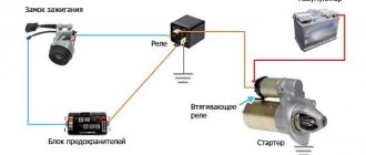
Like the starter solenoid relay, the ignition relay serves to remotely activate the starter motor and engage the bendix with the flywheel ring.
The relay operates on the basis of an electromagnet, where a coil is wound around a core.
Possible malfunctions and ways to eliminate them
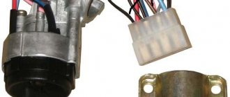
The nature of the lock assembly malfunctions on a VAZ 2109 car can also be electrical or mechanical.
The first group includes violations of the integrity of electrical circuits in the switch at a certain position of the key. If there is no contact, then the connected consumers may not work, or the car will not start at all. If there is contact, but the wrong parts of the circuit are closed, this is fraught with a short circuit and thermal damage to the lock. It will begin to melt and a characteristic smell will appear. Depending on the scale of the disaster, the contact group will most likely need to be replaced.
From a mechanical point of view, the core/larva may become stuck in some position. In this case, it will be physically impossible to turn the key in the lock. The only correct repair option is to replace the entire assembly.
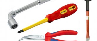
To diagnose faults in electrical circuits, you need to stock up on the following tools.
- Multimeter or tester. If it is not available, as an option, you can use a control light operating at 12V voltage.
- A set of screwdrivers and keys for dismantling the lock. Since the only option for repairing mechanical faults is to replace parts that have failed, they will come in handy in this case as well.
Before starting diagnostics, you will have to disconnect the terminal block and ring all contacts in the sequence that corresponds to each of the key positions. For clarity, you should have an electrical diagram of the unit at hand. If the circuit is closed, there will be a resistance indication on the device.
Replacing the lock should begin with de-energizing it. To do this, you will have to loosen the fastening nut and remove the negative terminal of the battery. After this, the protective and decorative casing and the turn/window washer switches are removed. The lock is attached to the steering column using four screws or two screws and a hook latch. It may be difficult to remove due to the screws. In this case, they will have to be cut or drilled, doing everything extremely carefully. The terminal block is disconnected, and the dismantling process can be considered complete.
Assembling a new lock assembly occurs similarly, but in reverse order.
Source
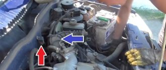
Removing the starter and connecting to the relay
VAZ 2110 starter protection relay
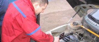
To disassemble the starter you need to follow several simple steps:
On a VAZ 2110 the starter relay is located
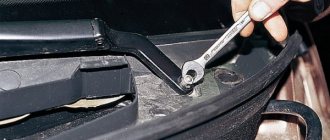
A wrench with the number “15” is used to unscrew the two nuts that secure the starter.
VAZ 2110 starter relay wiring diagram
Note: Please be advised that the bottom nut is quite difficult to access.
Assembling the starter and installing it in its original location occurs in the reverse order.
VAZ 2110 installation of an additional relay on the starter
The main malfunctions of the traction relay are several important problems. If one of the reasons is present, then the traction relay should be replaced with a new one.
VAZ 2110 starter relay clicks - needs to be replaced with a new one
If you continue to use a damaged relay in your car, other parts may suffer:
The main reasons for these problems may be:
Since the traction relay is part of the vehicle's electrical system, its repair or replacement must be carried out with care and special attention. This process can be dangerous to human health
The car can be entrusted to employees of technological service stations and repair shops. If you decide to carry out repairs yourself, you should follow all safety rules when working with electricity. Repair and replacement of equipment must be carried out on an observation platform or pit. A prerequisite is to remove the mudguard from the car engine. All the above steps must be carried out in strict order. After the process of dismantling the starter, you should perform a few more simple steps:
How to fix starter malfunctions with your own hands
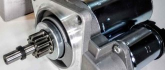
The electrical component of the starter consists of the following structural elements:
- winding;
- brush assembly;
- solenoid relay.
When checking the solenoid relay, skip the starter operation, bypassing its switching. The relay has 3 terminals at once, one of which is the control terminal. The remaining 2 large terminals, located at the input to the battery and at the output of the starter, are closed using a screwdriver or wrench. Closing for a short period of time is enough, the main thing is that the tool you are using does not touch the metal body directly under the hood.
Remember that starting the engine in this way is prohibited, because the main gear of the device does not engage.
Most likely, the contact planes on the inner plane simply burned out, and therefore a dielectric layer of metal oxides formed on top. To burn the contacts, there is no need to make great efforts; just one start of the VAZ-2109 engine is enough.
There are 2 ways to repair the VAZ-2109 solenoid relay:
- Dismantle the device and disassemble it into components, clean the contacts.
- If it is financially possible, it is better to replace the relay completely. Practice shows that if a relay fails, the contacts will have to be cleaned more and more often to restore its operation. If you want the repaired relay to last a long time, give preference to this option for repairing the starter if the device does not spin or click.
What is a relay (ignition relay) and what is it used for?
The ignition relay is used to remotely control the starter. It helps activate the electric motor and engage the bendix with the flywheel gear.
The operating principle of the relay is based on the operation of an electromagnet. A coil is wound around its core. As soon as voltage passes through the coil, an electromagnetic field is created inside. Under its influence, the armature moves inside the core.
The relay consists of a moving armature, an electromagnet, a return spring, a contact group and windings.
Ignition relay in diagram 7
The operating principle of the relay is detailed in the table below.
Replacing the ignition switch on a VAZ car
To carry out repair work to replace the ignition switch of a vase, we will need: a screwdriver, a tester and a thin awl. Once you have everything you need, you can begin the repair. On all classic VAZ cars, the ignition switch is located at the bottom, on the left of the steering column. To replace you need:
- Disconnect battery
- Remove the plastic casing by first unscrewing the screws that secure it.
- Then unscrew the two screws securing the ignition switch to the bracket.
- We insert the key and set it to position 0 to disable the anti-theft device.
- Insert the awl into the hole in the bracket and press the latch. Then we take out the lock itself.
- After removal, it is recommended to mark the contact wires so that nothing is mixed up the next time you connect.
Removing the ignition switch on a VAZ-2106 begins with disassembling the steering column casing. We unscrew the five bolts and remove its halves. Before you begin disassembling the electrical part of the lock, it is very useful to disconnect the battery by removing the negative terminal or unscrewing the switch bolt. After this, remove the spring retaining ring from the back of the lock body and remove the contact group. We move it to the side so that it does not interfere, and we begin to remove the lock itself.
It is secured in the steering shaft bracket with two bolts, after unscrewing which nothing happens. It is useless to try to remove the lock from its socket if you do not know about the special stopper. It is located on the lock body under the bracket. We press this stopper into the lock with a thin screwdriver through a small hole in the bracket. Further, according to all the instructions, the lock should be pulled out freely, but this does not work.
An obstacle that is not described anywhere is the anti-theft rod. Even though it is in a “disconnected” state, it still clings to the steering shaft. To remove the lock, you have to manipulate the key. In different positions of the lock cylinder, the anti-theft device also moves and is recessed as much as possible when the key is in the “Starter” position. After a few minutes the lock can be pulled out of the bracket.
Here is the time to write that assembly of the unit should be carried out in the reverse order of removal. And in general, this will be true. First you need to insert the new lock into the bracket, recessing the latch and holding the key in the starter position, tighten the fastening bolts, then connect the wires
Particular attention must be paid to this, because an incorrectly connected contact group can damage the starter or ignition system. We reconnect the wires from the old group to the new one one at a time, checking the numbers on the contacts
After this, we assemble the steering column casing.
First of all, you need to get rid of the decorative casing of the steering shaft, unscrew the fastening screws and remove it. We performed similar actions when replacing the steering shaft.
After removing the decorative casing, unscrew the two screws securing the ignition switch to the body, then insert the key into the lock and turn on the “0” position, which turns off the anti-theft device. Through the hole in the bracket, press the lock lock with a thin awl and remove the ignition switch from the mounting socket. This completes the repair work to remove the ignition switch.
To replace the contact group of the ignition switch, you need to use a thin screwdriver or an awl to pry the retaining ring from the edge and remove the contact part. When installing a new contact part, orient it so that terminals “15” and “30” are on the side of the locking rod.
At this point, the repair work is completed, install the new ignition switch in the reverse order of removal, connect the wires, transferring the markings from the old switch to the new one. The pinout or connection diagram of the VAZ ignition switch wires is quite simple and understandable, so every car enthusiast can carry out repairs or replace a spare part without the help of car service employees.
Didn't find the information you are looking for? on our forum.
We recommend reading:
VAZ 2107 heater fan fuse blows
Checking the ignition coil of a VAZ 2112 16 valves with a multimeter
Adjusting the rear axle gearbox of a VAZ 2106 at home
VAZ 2101-2107 bridge diagram, detailed description of parts
Replacing the ignition switch on a VAZ 2114, how to identify a breakdown, repair
VAZ 2112 cylinder head gasket burnt out, symptoms
What kind of oil to pour into the steering gear of a VAZ 2107
Dismantling and assembling the gearbox of a VAZ 2101 car. Video
Testing the serviceability
The lock's service life is limited. After it fails, it is necessary to repair or completely replace the product. The functionality is checked after inserting the key into the “secret”.
Failures occur due to mechanical wear or loss of contact. The check is carried out by turning the key. If it begins to jam, then as a temporary solution it is possible to use silicone grease by dripping it inside.
In order for the wiring diagram to function correctly, you need to know which contacts to connect to each other. Typically the following wiring system is used:
- red connects to the cable from the starter;
- the pink wire goes to “+” from the 12 V battery;
- brown +12 V is used to start the ignition relay;
- white – relay on;
- black and blue connect other consumers.
It is necessary to check the contacts for the presence of carbon deposits or the possibility of oxidation. Burning contacts can be heard in the cabin by the characteristic smell of burnt insulation.
For the VAZ 2109, as well as for all other cars, the ignition switch is one of the most basic elements of electrical equipment. This element consists of a mechanical and electrical part. The mechanical part is responsible for locking the steering wheel when there is no key in the lock, and the electrical part is responsible for supplying voltage to the necessary electrical circuits depending on the selected position.
Where are the fuses VAZ-2108 2109 21099
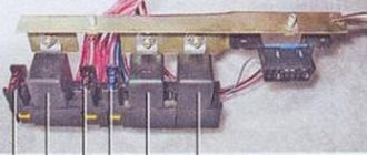
The relay and fuse block for the VAZ 2108-09-099 (carburetor, injector) is located under the hood, in the compartment in front of the windshield on the left side.
Fuse mounting block 2114-3722010-18
- K1-relay for turning on headlight cleaners;
- K2-relay-breaker for direction indicators and hazard warning lights;
- K3 - windshield wiper relay;
- K4-relay for monitoring the health of lamps;
- K5-power window relay;
- K6 - relay for turning on sound signals;
- K7-relay for turning on the electric heating of the rear window;
- K8-relay for high beam headlights;
- K9-relay for low beam headlights;
- F1-F16 - fuses
Fuse mounting block 2114-3722010-60
- K1 - Relay for turning on headlight cleaners
- K2 - Relay interrupter for direction indicators and hazard warning lights
- K3 - Windshield wiper relay
- K4 - Relay for monitoring the health of brake lamps and side lights
- K5 - Power window relay
- K6 - Horn relay
- K7 - Heated rear window relay
- K8 - Headlight high beam relay
- K9 - Relay for low beam headlights
- F1 - F16 - Fuses
- F1 - F20 - Spare fuses
Fuse mounting block 17.3722
- 1 - relay for turning on headlight cleaners (K6)
- 2 - rear window washer time relay (K1)
- 3 - relay-breaker for direction indicators and hazard warning lights (K2)
- 4 - windshield wiper relay (KZ)
- 5 - contact jumpers in place of the lamp health monitoring relay
- 6 — relay for turning on the heated rear window (K10)
- 7 - spare fuse
- 8 - headlight high beam relay (K5)
- 9 - relay for low beam headlights (K11)
- 10 - fuse
- 11 — relay for switching on the electric motor of the engine cooling fan (K9)
- 12 - horn relay (K8)
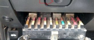
Description of the mounting block fuses for VAZ 2109, 2108, 21099
F1-F16 - mounting block 2114-3722010-60, 2114-3722010-18.
Numbers from 1 to 16 - old-style mounting block 17.3722
| Fuse no. | Decoding |
| 1 (8 A) F9 (7.5 A) | Right fog lamp |
| 2 (8 A) F8 (7.5 A) | Left fog lamp |
| 3 (8 A) F1 (10 A) | Headlight cleaners (at the moment of switching on). Relay for turning on headlight cleaners (contacts). Headlight washer activation valve |
| 4 (16 A) F7 (30 A) | Headlight cleaners (in operating mode). Relay for turning on headlight cleaners (winding). Heater fan motor - heater fuse Window washer motor. Rear window wiper motor. Rear window washer timing relay. Valves for turning on the windshield and rear windows. Relay (winding) for turning on the electric fan of the engine cooling system. Relay (coil) for turning on the heated rear window. Rear window heating indicator lamp. Glove compartment lamp |
| 5 (8 A) F16 (15 A) | Direction indicators and relay-interrupter for direction indicators and hazard warning lights (in turn indication mode). Turn signal indicator lamp. Rear lights (reversing lamps). Gearmotor and windshield wiper activation relay. Generator excitation winding (when starting the engine). Brake fluid level warning lamp. Oil pressure warning lamp. Carburetor air damper warning lamp. Parking brake warning lamp. "STOP" light display lamp. Coolant temperature gauge. Fuel level indicator with reserve warning lamp. Voltmeter |
| 6 (8 A) F3 (10 A) | Rear lights (brake lamps). Interior lighting |
| 6 (8 A) F6 (30 A) | Power windows for front doors. Power window relay |
| 7 (8 A) F10 (7.5 A) | License plate lights. Engine compartment lamp. Instrument lighting lamps. Indicator lamp for external lighting. Heater lever illumination display. Cigarette lighter lamp |
| 8 (16 A) F5 (20 A) | The electric motor of the engine cooling system fan, and its activation relay (contacts). Sound signal and relay for its activation |
| 9 (8 A) F10 (7.5 A) | Left headlight (side light). Left rear light (side light) |
| 10 (8 A) F11 (7.5 A) | Right headlight (side marker). Right rear light (side light) |
| 11 (8 A) F2 (10 A) | Direction indicators and hazard warning relay-breaker (in hazard warning mode). Hazard warning lamp |
| 12 (16 A) F4 (20 A) | Rear window heating element. Relay (contacts) for turning on the heated rear window. Plug socket for portable lamp. Cigarette lighter |
| 13 (8 A) F15 (7.5 A) | Right headlight (high beam) |
| 14 (8 A) F14 (7.5) | Left headlight (high beam). Indicator lamp for high beam headlights |
| 15 (8 A) F13 (7.5 A) | Left headlight (low beam) |
| 16 (8 A) F12 (7.5 A) | Right headlight (low beam) |
Fuses and relays Volkswagen Golf 6, 2008 - 2013
The main power supply circuits of the vehicle's electrical equipment are protected by fuses. Headlights, fan motors, fuel pump and other powerful consumers are connected via relays. Fuses and relays are installed in mounting blocks, which are located in the engine compartment and interior of the car. The information is relevant for Volkswagen Golf 6 models 2008, 2009, 2010, 2011, 2012, 2013.
In the cabin
1) To access the fuse mounting block located in the passenger compartment...
2) Pry up the edge of the cover of the mounting block 3) overcoming the resistance of the latches, remove the cover Fuses in the mounting block located inside the car
| Assignment of fuses in the interior mounting block | ||
| Number | Current, A | Protected circuit |
| 1 | 10 | Control unit for electric headlight corrector and instrument cluster illumination brightness, parking assistance system |
| 2 | 10 | Brake light switch, ambient light switch, ABS system, instrument cluster, electric power steering, fuel module |
| 3 | 5 | Restraint control unit |
| 4 | 5 | Emergency oil level drop sensor, heating system control unit, ventilation air conditioning control unit, ASR switch, reverse light switch, interior rear view mirror with automatic dimming, automatic parking system |
| 5 | Reserve | |
| 6 | ||
| 7 | ||
| 8 | ||
| 9 | ||
| 10 | ||
| 11 | ||
| 12 | 10 | Window control unit |
| 13 | 10 | Exterior light switch, diagnostic connector, rear view camera, rain and light sensors |
| 14 | 10 | Heating, air conditioning and ventilation control unit |
| 15 | 20 | Body equipment control unit |
| 16 | Reserve | |
| 17 | 5 | Alarm buzzer |
| 18 | Reserve | |
| 19 | ||
| 20 | ||
| 21 | ||
| 22 | 20 | Air blower |
| 23 | 30 | Front door power window control keys |
| 24 | 20 | Rear door power window control keys |
| 25 | 25 | Electrically heated tailgate window |
| 26 | 30 | Rear door power window control keys |
| 27 | 15 | Gasoline pump |
| 28 | Reserve | |
| 29 | ||
| 30 | 20 | Mechatronic unit for robotic gearbox |
| 31 | 20 | Brake vacuum pump |
| 32 | 30 | Socket for connecting additional equipment |
| 33 | 25 | Power sunroof |
| 34 | 15 | Front seat lumbar support adjustment switch |
| 35 | 10 | Electronic damping control system control unit |
| 36 | 20 | Headlight washer pump |
| 37 | 30 | Front seat heating control unit |
| 38 | Reserve | |
| 39 | ||
| 40 | ||
| 41 | 15 | Tailgate window wiper motor |
| 42 | 20 | Cigarette lighter |
| 43 | 15 | Trailer stability control unit |
| 44 | 20 | |
| 45 | 15 | |
| 46 | Reserve | |
| 47 | ||
| 48 | ||
| 49 | ||
Relay in the mounting block located in the passenger compartment
Check and replacement
If the car shows signs of malfunction, there are signs of breakdown of elements of the ignition system, do not rush to immediately blame the starter or module for everything. Often the culprit may be an element that is insignificant in size and cost - the relay.
Dismantling works
To check the relay you need:
- Arm yourself with an ohmmeter or a multimeter more suitable for a motorist, which has all the necessary modes;
- Check resistance indicators;
- We check the holding coil by connecting one terminal of the tester to the relay connection terminal, and the second to ground, that is, the housing;
- Next, the pull-in winding is checked. Here the terminals are connected to the starter motor field winding connection bolt and the control wire connection bolt;
- If there is no resistance, there is only one output - failure.
Checking with a multimeter There is no point in repairing the ignition switch. The element can only be replaced. Plus, it costs pennies.
To replace, you will need to perform a few simple steps. You don't have to be a car repairman here.
- Disconnect the battery by removing the negative terminal.
- Using a slotted screwdriver, unscrew the four screws on the steering column housing. This will allow you to easily remove the element.
- Using a Phillips screwdriver, unscrew another screw that holds the bottom of the casing in place.
- Remove the steering column protective cover.
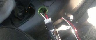
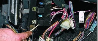
- At the bottom there is a block of the harness with wires where the ignition relay is connected.
- To replace the relay, you simply need to disconnect the device from the block and install a new element in its place.
- Check the performance of the car with a new transmission.
As you can see, there is nothing difficult about checking and replacing the device. It does not fail very often, but it is worth monitoring the condition of the ignition relay.
Design and operating principle
When an electric current passes through the coil, an electromagnetic field is created, under the influence of which the armature moves inside the core. When the power is cut off, the field disappears and the armature begins to move freely along the core.
The ignition relay includes the following components:
The electromagnet, in turn, includes two coils in its design.
Coil type
Peculiarities
It is connected to the ignition relay housing, as well as the control output
The retractor coil is connected to the motor contact as well as the control terminal
Device location
The operating principle of the node is based on the following:
How to find a fault when the main relay does not turn on?
How to find a fault if the engine does not start due to the main relay. First, find a place to install it on the car. It is mainly installed next to the fuel pump relay and the radiator cooling fan relay.
The fuses for the engine management system, fuel pump and radiator cooling fan are also installed there. On VAZ - 2107, VAZ - 2109 cars and its modifications, it is located on a shelf under the glove compartment or under it. On VAZ-2110 and similar cars, under the side of the heater console, on the passenger side. On GAZ cars, they are usually located under the hood on the front wall of the cabin closer to the passenger side.
If, when you turn on the ignition, you do not hear the characteristic click of the relay turning on, you need to use a test lamp connected to the minus to check the presence of power at terminals 85 and 86 of the main relay socket. When using a test lamp, its current consumption should not exceed 0.25A, otherwise damage to the controller may occur. If the control lamp does not light up on any terminal, then the relay is not receiving power. This may be caused by a blown fuse or a broken power cord. In the case when the lamp burns brightly on one terminal, and at half-glow on the second, and the relay may be activated, you should remove the relay from the socket and connect terminals 85 and 86 with a test lamp. When the ignition is turned on, the control lamp should light up. If this is the case, then it is necessary to eliminate the poor contact in the connection of the relay with its block. If the control lamp does not light up, it is necessary to check the integrity of the wire following from the relay to the controller and the contact of the negative wires from the controller to the engine body. On VAZ cars, these wires are attached to the end of the cylinder head above the thermostat, and on GAZ cars to the connecting pin of the receiver and intake manifold in the area of the fourth cylinder. If the wires are OK, but the relay does not turn on, the controller is faulty. For example, on Volga cars, a common malfunction in this case is a break in the negative wire or water getting into the controller, which leads to its malfunction.
If, when you turn on the ignition, there is a click and the relay is activated, then you need to check the power supply at terminals 87 and 30. To do this, touch terminal 87 with the test lamp connected to the minus. If the test lamp does not light up, then possible malfunctions may be a blown fuse or wire break. If there is a plus on pin 87, but when the relay is turned on, there is no positive on pin 30, it means that the relay contacts have burned out and it should be replaced. On VAZ cars, for this you can use a suitable relay from the mounting block, for example a relay for turning on signals, low or high beam headlights, and so on. When searching for a malfunction in which the main relay does not turn on, it is necessary to take into account the presence of anti-theft systems on the car. When installing them, it is not uncommon to include a blocking relay in the relay circuit, which breaks its power supply circuit when the alarm is triggered.
Source
What is a relay for?
Fuses and relays Replacing the starter relay on a VAZ 2110
The traction relay ensures that the drive gear starts. Starting occurs in clutch with the gear mechanism of the crankshaft flywheel. It also provides power to the starter motor. When the starter is turned on, energy begins to be transferred from the battery. The energy path passes through the ignition switch.
VAZ 2110 additional starter relay
In this way, power is supplied to each winding of the traction relay. Windings have two types:
As soon as the process of closing the relay contacts takes place, the retractor winding is turned off. A working relay has a voltage limit that should not exceed 8 V. The temperature during this process should not exceed 25 degrees Celsius
If the voltage when starting the relay exceeds this indicator, then you should pay attention to the drive and the traction relay itself. They may become damaged or stop working
The traction relay can be visually examined. Perhaps the breakdown can be seen with the naked eye, but the starter will have to be dismantled and disassembled.
VAZ 2110 starter lock relay
Where is the fuel pump located on the VAZ-21099 injector
Removing and installing a gasoline pump (PG) is not a difficult job and does not require extensive plumbing experience or high qualifications. But if you don’t have to look for a fuel pump on carburetor cars for a long time (it is located on the engine, under the hood), then a beginner may not find it on the injector on the first try. Where is the fuel pump located on the VAZ-21099 sedan injector? Let's figure it out step by step:
- we move the front seats in the car forward as much as possible to free up space in the rear;
- open the rear left door of the car, find a small hinge on the rear sofa, which is located at the junction of the “seats” approximately in the middle of the cabin;
- pull the loop up, thereby raising the back of the lower seat;
- under the carpet we see the gas tank flap;
- unscrew the two fastening screws, remove the hatch and find the fuel pump underneath.
Schemes 2108, 2109, 21099
Scheme of VAZ-2108, 2109 with a low instrument panel (early versions)
There is a “parking light” function - turning on the left or right lights when parking.
Scheme of VAZ-2108, 2109, 21099 with a low panel (later versions)
There is no brake pad wear sensor (previously, the handbrake lamp blinked when the lever was raised, and lit up constantly when the sensors on the brake pads were activated).
Years of production 2108: 1984—2003 in Russia, 2003—2014 in Ukraine
VAZ-2108
Scheme of VAZ-2108, 2109, 21099 with a high luxury panel
Fog lights, central locking, trip computer and electric windows.
Scheme of VAZ-2108, 2109, 21099 with a high panel and Euro fuse block 2114
Fog lights, central locking, heated seats and electric windows.
Scheme of VAZ-21099 with Europanel (production since 1998)
Years of production 2109: 1987-2004 - in Russia, 2004-2011 - in Ukraine
VAZ-2109
Engine control system diagrams
Instrument cluster diagram for low panel
Instrument cluster diagrams for high panel
Connection diagram for headlight cleaners on low and high panels of cars produced after 1989
The headlight cleaners are turned on by a button, in place of the relay there is a jumper.
Years of production 21099: 1990-2004 - in Russia, 2004-2011 - in Ukraine
VAZ-21099
Scheme of a microprocessor ignition system with an MC2713 controller
Scheme of a microprocessor ignition system with an MC4004 controller
Diagram of a mixture control system with a controller under the hood
Diagram of a mixture control system with an under-seat controller
Changes in electrical equipment with rotary motor
Diagram for switching on fog lights since 2000 on a high panel
Since 2000, in accordance with UNECE rule 48-01, the electrical circuit for switching on the rear fog lights has been changed on parts of VAZ vehicles. Added rear fog light relay 2114-3747610, and rear fog light switch 21093-3710030-10 (like a regular one, only without fixing). Instrument panel harness used 21099-3724030
MEGABONUSES
We are reworking the activation of the rear fog lights according to the latest scheme. That is, the button will not be fixed: if the headlights or front fog lights are on, press and release the button for the rear fog lights - they turn on. They turn off when you press the button again or automatically when you turn off the headlights. That is, we will never forget to turn them off. For high panel.
You need rear fog lamp relay 2114-3747610. It may look different, it is also used on the VAZ-2114, 2110, GAZ-3110... It is advisable to find a connector for it, you can just wrap the usual terminals with electrical tape and stick it in.
Remove the jumper from the button
Reworking the connection
Contact 1 of the relay is constant power. You can connect it to the ignition, for example to the yellow-blue heated glass button, then the rear fog lights will sit on the heater fan fuse.
Reasons for heating
Of course, the relay should not get hot. Often, heating of the device is caused by a short circuit in the wiring to ground. Water is getting in somewhere through the connector, maybe there is a malfunction in the control unit. And, obviously, the relay is heating up due to its malfunction (how to replace the device is at the end of the article).
Insufficient relay amperage
So, let's start with the fact that the relay can heat up due to insufficient amperage. For example, if the device indicates 70 A, then such a relay is not designed for long-term loads. It is installed, as a rule, only for the starter.
In fact, this part is responsible for heating the rear window, supports some low-current electrical circuits, and controls the car's washer and heater. In a word, a small detail in appearance, but with a wide purpose.
You can try removing one or more consumers, except the starter, and check if the device stops heating. If yes, it stops, then the reason lies in a weak relay. We advise you to install a more powerful one, with a higher amperage.
Wrong connection diagram
Another option: the wrong scheme. It happens that after an electrical repair or repair, a specialist did something incorrectly. For example, I made a different relay connection diagram that was not consistent with the standard design.
The classic scheme for the operation of a relay is the closure of contacts 87-30 as soon as current appears at 85-86. An impulse from the device is instantly sent to the starter, and the car starts.
However, there are other schemes. For example, the current flows constantly at 85-86, but the starter starts only after turning the ignition key. This is the option that leads to heating of the relay, since it is constantly turned on (current flows constantly to the device).
To check this point, it is recommended to measure the voltage between terminals 85 and 86. There, with the ignition half-on, there should not be 12V at all, that is, voltage coming from the battery. When the ignition is on, the plus goes to pin 86, and the minus goes to pin 85.
Article on the topic: Peugeot 307 starter
VAZ 2109 generator circuit
If you lose charge, this is most often due to a failure of the generator, and most often it is the generator brushes, but it happens that there are winding breaks and a short circuit in the circuit or an open circuit. In this case, I recommend that you familiarize yourself with this generator circuit for the VAZ 2109.
Download diagram
Numerical designations on the diagram
| 1. Generator. | 2. Negative valve. | 3. Additional diode. |
| 4. Positive valve. | 5. Battery discharge warning lamp. | 6. Instrument cluster. |
| 7. Voltmeter. | 8. Mounting block. | 9. Additional resistors of 100 Ohm, 2 W. |
| 10. Ignition relay. | 11. Ignition switch. | 12. Rechargeable battery. |
| 13. Capacitor. | 14. Rotor winding. | 15. Voltage regulator. |
Design and principle of operation of the lock assembly
On a VAZ 2109 car, 2 standard modifications of the lock can be installed. The old one has catalog number 21080-3704005-60. It features four key positions (long), and also contains an ignition relay. The new unit with catalog number 21080-3704005-30 has only three key positions and does not have a relay.
To connect all the wires to the VAZ 2109 car lock, a contact group is used. Each of the key positions has its own blocking, and therefore consumer groups.
Where is the fuel filter located?
The fuel filter (TF) on the VAZ-21099i is designed to clean gasoline from debris, dirt and various impurities; it is a monolithic structure with a rigid metal body and a filter element inside. The frequency of its replacement is every 20-30 thousand km of the distance traveled, also if the car begins to move jerkily, and diagnostics showed that the fuel pump is clogged.
It’s easy to find out where the fuel filter is located; to do this, you need to install the car on an inspection hole or a car lift. The TF is located on the bottom of the body, next to the rear beam and the gas tank, and is secured with a special clamp, which is tightened with a bolt and nut.
Before you start changing the filter, you need to relieve the fuel pressure, otherwise when you unscrew the fuel fittings, gasoline will splash under high pressure. You can relieve pressure in the line using a special nipple located at the rear of the fuel rail. Before starting such an operation, it is necessary to prepare a plastic container into which gasoline should be poured, then unscrew the safety cap.
To release the pressure, you can use a standard flat-head screwdriver; when you press the nipple valve, gasoline will come out of the system.
After removing fuel from the line, we proceed to replacing the fuel pump.
The most common ignition switch problems.
Many owners of "nines" note one unpleasant feature of their iron "horses" - that over time, the ignition switch in them simply begins to jam. Even if it was installed quite recently. Most likely, this defect is a manufacturing defect and you need to contact the store where you purchased the new ignition switch (for this purpose, it is better to save receipts for such purchases) to make a return. However, if this option is not available to you, do not despair!
The fact is that when the ignition switch jams when starting the engine, voltage is supplied to the starter, which can lead to failure of this part. But this does not mean at all that you need to run to the auto store for a new part. In this situation, you can simply buy silicone grease and apply it inside the lock every time the lock jams.
Ignition switch consumers.
This article will be useful to those who want to upgrade the ignition switch (for example, start the engine with a button) or are experiencing problems with the lock. Only the electrical part of the lock is described. We will consider the ignition switch in the VAZ-2114 version. It, unlike the VAZ-2108 lock, works in conjunction with the ignition relay.
The lock has 4 positions, of which only 3 are actually used:
0 - all consumers are turned off (used extremely rarely) 1 - ignition is on 2 - starter is on 3 - parking (the key is removed from the lock) Voltage from the battery is always supplied to contacts 7 (pink) and 8 (brown) of the lock. These wires are connected in parallel and connected in the mounting block. The division into two wires was apparently done for reliability, or it may have developed historically - these wires can be replaced with one wire. The brown wire connects the ignition system (carburetor version), instrument panel and some other consumers. Pink is responsible for the rest of the load.
Design and operating principle
When an electric current passes through the coil, an electromagnetic field is created, under the influence of which the armature moves inside the core. When the power is cut off, the field disappears and the armature begins to move freely along the core.
The ignition relay includes the following components:
The electromagnet, in turn, includes two coils in its design.
Coil type
Peculiarities
It is connected to the ignition relay housing, as well as the control output
The retractor coil is connected to the motor contact as well as the control terminal
Device location
The operating principle of the node is based on the following:
If you installed it yourself
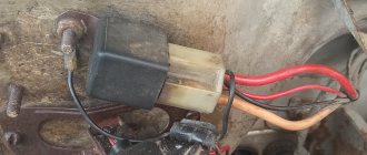
The previous owner of the car, in the absence of such a standard part, could install it himself. Such installation kits are sold in car dealerships. In this case, the electric relay can be located not only in the “standard” location. Finding it without calling the previous owner will not be so easy.
If a breakdown of this part occurs on the way, then you can start the car by closing contacts 87 and 30 (the location and circuit diagram are printed on the top of the relay housing). In this case, you are allowed to use the machine without any restrictions. But at the first opportunity, be sure to fix the breakdown. The operation of the VAZ-2115 ignition system directly depends on the relay.
How to check
After turning the ignition key to the “ON” position, the main relay is turned on and power is supplied to everything except the starter system of the vehicle. At this moment, a buzzing sound will be heard in the area of the gas tank - the operation of the fuel pump. Further turning of the key will close the contacts of the starter relay and start it. When you repeatedly try to turn the starter, such a sound will most likely not be heard, and this is not a malfunction. The fuel line is filled with gasoline, and the pressure sensor will not allow the pump to start when the engine is not running.
Where is the speed sensor located?
The speed sensor (DS) on front-wheel drive VAZ cars reads pulses depending on wheel speed and transmits the data to the electronic control unit (ECU). When braking the engine, the fuel supply is turned off with the help of the diesel engine and the computer, thus achieving more economical operation of the internal combustion engine. If the sensor is faulty, an error code is recorded, gasoline consumption increases slightly, and idle speed decreases, especially during heavy braking. It is difficult to immediately detect where the speed sensor is located, since it is hidden under the air filter housing (AFC).
We find the part we need as follows:
- open the hood of the car;
- Using a 10mm wrench, unscrew the two KVF fastening bolts;
- loosen the clamp of the air “corrugation”, disconnect the “chip” with the wires;
- we take out the KVF, now the sensor has already appeared in the field of view, it is located on the gearbox (gearbox) housing, wires are connected to it, connected using a connector.
The DS can be easily unscrewed by hand, and the plug with wires can be pulled out even after the sensor has been unscrewed (but carefully so as not to damage the wiring during rotation).
Location and electrical diagram
On older models (manufactured before 1998), the relay and fuse mounting block is marked 17.3722. This device consists of a plastic case, which, in turn, has a lower part and a cover, as well as an engineering board. It is to this board that the wire contacts are soldered, and fuses and relays are installed.
As for newer car models, that is, those released after 1998, their power supply units are marked with the numbers 2114-3722010-60. Fuses are installed in them (hereinafter referred to as FCs) and these blocks differ from each other by their electrical circuit and some nuances in the purpose of the elements. It is worth noting that regardless of whether your car is fuel-injected or carburetor-powered, the design and electrical circuit of the power supply will depend on the year of manufacture, and not on the type of fuel supply.
We are reporting this in order to dispel the myth that is circulating among Russian motorists. Drivers seriously believe that the layout and design of the unit depends on the fuel supply system, but we assure you that this is not the case.
The main difference between these two types of power supply is:
- different designations of device parts;
- different fuse ratings;
- In addition, the manufacturer decided that when developing a new power supply, it was necessary to remove the cooling system fan motor relay, as well as the device time relay.
Marking 17.3722
Let's take a look at the electrical circuit of the old-style power supply unit, as well as the purpose of the fuses. As we said at the beginning of the article, a power supply with such a circuit can be found in a VAZ 2109, both equipped with an injection and a carburetor engine.
If you are the owner and your heater fuse or fuel pump fuse has failed, for example, then it would be useful for you to know the purpose of the unit’s parts.
In addition, information about the purpose of the relay will be useful to you. It is presented below.
| Number | Purpose |
| 1 | Responsible for the functioning of the headlight cleaning elements. |
| 2 | This relay determines the functionality of the rear window washer motor. |
| 3 | This component protects against failure of the turn signal lamp lamps, as well as light signaling. |
| 4 | Protects the windshield wiper motor from damage. |
| 5 | Using these jumpers you can determine whether the lamp is working or not. |
| 6 | This component protects the rear window defroster mechanism from overvoltage. |
| 8 | High beam headlight bulbs. |
| 9 | Low beam headlight bulbs. |
| 11 | Without this device, the engine cooling fan will not be able to operate. If this device breaks down, there is a possibility of the motor overheating. |
| 12 | Responsible for the operation of the horn. |
Additional block
It is located in the cabin, under the panel on the right, mainly on cars with injection engine types.
Scheme
Decoding
Relay
We have also prepared a video on this publication on our channel. Watch and subscribe.
Still have questions? Ask them in the comments.
Comments 1
Hello. I have a VAZ 99. Year of manufacture 1998. The car has been converted. I have an injection one. ECU January. Now the question is - is there a difference in the carburetor fuse block from the injection one? I have a block before the 1st sample (finger type), the car sometimes does not start, in general there are a bunch of reasons. A month ago I opened the block, water got in there, I didn’t bother and bought a used one exactly like this and installed it. after replacement even more problems. Should I install another block? Please let me know.
Source