VAZ 2110 2111 2112 (injector) fuses and relays
VAZ 2110 2111 2112 (Lada 110 111 112) - a family of cars produced in 1995, 1996, 1997, 1998, 1999, 2000, 2001, 2002, 2003, 2004, 2005, 2006, 2007, 2008 and 2009 with sedan and hatchback bodies and a station wagon mainly with 8 and 16 valve gasoline engines ( injector , carburetor). In this article you will find a description of the fuse and relay blocks of the VAZ 2110 2111 2112 with diagrams , photographs and their locations. Electrical connection diagram. Let's highlight the fuse responsible for the cigarette lighter.
The purpose of fuses and relays in your VAZ 2110 (2111 / 2112) relay may differ from those presented and depend on the year of manufacture. The current purpose can be printed on the block itself.
Characteristics of the HR16DE-Н4М motor
| Cylinder arrangement | in one row |
| Number of bars | 4 |
| Number of cylinders | 4 |
| Volume, l | 1,598 |
| Cylinder liner diameter, mm | 78,0 |
| Piston stroke in cylinder, mm | 83,6 |
| Compression ratio | 9.5 (10.7 for H4Mk 110 hp engine) |
| Number of valves per cylinder | 4 (2-inlet; 2-outlet) |
| timing belt | DOHC (with two camshafts, one for the intake valves, the other for the exhaust valves) |
| The cylinders operate in the following order | 1-3-4-2 |
| Nom. engine power/at engine speed | 83.5 kW - (114 hp)/6000 rpm |
| Max. torque | 153 N•m (at 4400 rpm) |
| Fuel system | with electronically controlled injection distribution |
| Number of fuel injectors | 2 for each cylinder |
| Runs on octane gasoline | 95 (92) |
| Environmental friendliness | euro 5 |
| Weight, kg | 105.4 |
| Years of manufacture | produced since 2006 |
| Recommended oil for lubrication system | ELF 5W30 5L (similar to SHELL 5W30 5L) |
| Engine oil volume, l | 4.3 |
| Oil change intervals | every 15,000 km, but at least once a year |
| Frequency of air filter replacement | after 45 thousand km. |
| Frequency of replacement of spark plugs (number 224012331R NGK PLZKAR6A-11) | after 30 thousand km. |
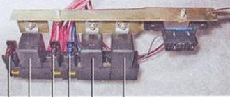
Main unit
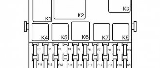
The main block with fuses and relays is located in the cabin, on the left side, under the control panel. To access, press the latch switch.
Photo - diagram Option 1
Scheme Option 2
Scheme Option 3
Description of fuses
p, blockquote 15,0,0,0,0 —>
| F1 | 5A Lamps for license plate lights. Instrument lighting lamps. Side light indicator lamp. Trunk light. Left side marker lamps |
| F2 | 7.5A Left headlight (low beam) |
| F3 | 10A Left headlight (high beam) |
| F4 | 10A Right fog lamp |
| F5 | 30A Electric motors for glass door lifts |
| F6 | 15A Portable lamp |
| F7 | 20A Electric motor of the engine cooling system fan. Sound signal |
| F8 | 20A Rear window heating element. Relay (contacts) for turning on the heated rear window |
| F9 | 20A Recirculation valve. Windshield, rear window and headlight cleaners and washers. Relay (coil) for turning on the rear window heating |
| F10 | 20A Reserve |
| F11 | 5A Starboard side marker lamps |
| F12 | 7.5A Right headlight (low beam) |
| F13 | 10A Right headlight (high beam). High beam warning lamp |
| F14 | 10A Left fog lamp |
| F15 | 20A Electric seat heating. Trunk lock lock |
| F16 | 10A Relay - turn signal and hazard warning light switch (in hazard warning mode). Hazard warning lamp |
| F17 | 7.5A Interior lighting lamp. Individual backlight lamp. Ignition switch illumination lamp. Stop lamps. Clock (or trip computer) |
| F18 | 25A Glove box lighting lamp. Heater controller. Cigarette lighter. |
| F19 | 10A Door locking. Relay for monitoring the health of brake light lamps and side lights. Direction indicators with warning lamps. Reversing lamps. Generator excitation winding. On-board control system display unit. Instrument cluster. Clock (or trip computer) |
| F20 | 7.5A Rear fog lamps |
Fuse number 18 at 25A is responsible for the operation of the cigarette lighter.
The fog lamp fuse is installed separately in the instrument panel niche behind the main unit.
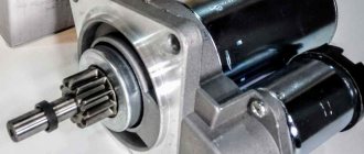
Ignition relay VAZ 2107, 2105, 2104
An ignition relay is installed in the ignition system of VAZ 2107, 2105, 2104 cars.
Ignition relay for VAZ 2107, 2105, 2104 cars
— Purpose of the ignition relay
The ignition relay is designed to reduce the current flowing through the low-voltage part of the ignition system. This prevents burning of the ignition switch contacts and their premature failure.
Because of this, the ignition relay is also called a unloading relay.
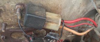
— Where is the ignition relay located on a VAZ 2107, 2105, 2104?
The ignition relay on VAZ 2107, 2105, 2104 cars is installed under the instrument panel, next to the ignition switch, to which it is connected by wires.
— How does the ignition relay work?
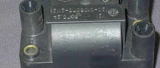
The ignition relay for VAZ 2107, 2105, 2104 cars is electromagnetic. It consists of an electromagnet (core with a winding) and contacts that close when voltage is applied to it. The relay has four terminals. Relay input is contact “86”, output is “87”, constantly energized “30”, ground is “85”. From above, the entire system is closed by a housing. The body has a bracket (eyelet) for fastening.
Relay 113.3747-10 (ignition relay), device
— How does the ignition relay work for VAZ 2107, 2105, 2107?
When voltage is applied from terminal “15/1” of the ignition switch (turning the key) to terminal “86” of the relay, its electromagnet is activated, the moving and fixed contacts are closed inside, electric current begins to flow through them from terminal “30” to terminal “87” and then through the mounting block to terminal “B” (“C”) of the ignition coil (primary winding). The coil is charged and ready for use. The ignition relay contacts will be in the closed state while the ignition system is operating (ignition is on). This is a continuous relay. After de-energizing, the relay contacts open.
The easiest way to track the operation of the relay is using the ignition system diagram.
Diagram of the contactless ignition system for VAZ 2105, 2107, 2104
— Malfunction of the ignition relay
As a result of a short circuit or voltage surges in the vehicle's on-board circuit, the relay winding may burn out or its contacts may burn out. After which the car engine cannot be started (the starter turns, but the engine does not start). The easiest way to check the serviceability of the relay is to replace it with a similar one from the mounting block.
In some cases, you can try to revive a faulty relay by cleaning its contacts and setting a gap of 0.1 mm between them. But if the winding burns out, then the relay only needs to be replaced.
— Applicability of the ignition relay in the ignition system of VAZ 2107, 2105, 2104
The ignition system of the carburetor engine of VAZ 2107, 2105, 2104 cars uses an ignition relay 113.3747-10 with a mounting bracket. It is similar to relay 113.3747 (without bracket).
Notes and additions
Characteristics of relay 113.3747-10
Rated voltage - 12 V
Triggering voltage - 8 V
Release voltage - 1.5-5.5 V
Load current - 20 A
Winding resistance - 85±8.5 Ohm
Twokarburators VK - More information on the topic in our VKontakte group, on Facebook Twokarburators FS and on Odnoklassniki - Twokarburators OK
More articles on the ignition system of VAZ 2107, 2105, 2104
— A capacitor in the distributor, why is it needed?
— Why do you need an interference suppression resistor in the distributor?
— Centrifugal ignition timing regulator for distributor VAZ 2107, 2105, 2104
— Vacuum ignition timing regulator in the VAZ 2107, 2105, 2104 distributor
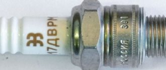
— Candle A17DV, applicability and characteristics
— Wires of the ignition switch VAZ 2107
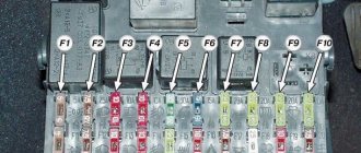
Additional block
It is located under the center console and is covered with a lid. One part is accessible from the right side.
Designation
p, blockquote 27,0,0,0,0 —>
- 15A - Ignition module, controller
- 15A - Canister purge valve, vehicle speed sensor, oxygen concentration sensor (heating), air flow sensor
- 15A - fuel pump, fuel pump fuse, injectors
- Electric fan relay
- Fuel pump relay
- Main relay (ignition relay)
The other part is on the left side of the console:
Decoding
p, blockquote 31,0,0,0,0 —>
- Central locking control unit
- Immobilizer block
- Relay for turning on rear fog lights.
On our channel we also prepared a video on this publication. Watch and subscribe.
p, blockquote 33,0,0,0,0 —> p, blockquote 34,0,0,0,1 —>
Do you know how to make the material better? Write in the comments.
Source
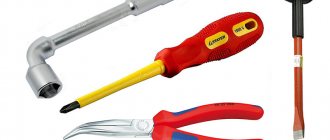
Contact devices
They can easily be considered one of the most common components used on cars. They include the following parts:
- The current source is a car battery or generator;
- Ignition switch;
- Ignition distributor breaker;
- Distributor or distributor;
- Coil for generating high voltage voltage.
In the figure you can see an approximate diagram of such a device.
Regardless of what type of device is installed on the machine, it will use five basic elements. Let's look at their description in more detail:
- During startup and operation of the engine, a current source will be required to generate a spark to ignite the working mixture. At first, such a source is a battery, and then a working generator set;
- The ignition switch, maybe a button, supplies on-board voltage to the circuit of this device;
- A high-voltage storage device, drivers call it a bobbin;
- Ignition distributor breaker;
- Plugs for igniting the air-fuel mixture.
Relay and fuse blocks VAZ 2112: description and explanation
Modifications of mounting blocks and fuses of the VAZ 2112 have changed more than once during the production of the model. Radical innovations were introduced only in 2002 after the appearance of a 16-valve injector.
In 2006, there was only one unit in the cabin, and in 2007 a console unit was added to it. This happened thanks to changes in the shield and gearbox, and the addition of a Europanel. The cover of the main unit became hinged, which simplified access to the fusible elements. Separate inserts outside the mounting blocks, for example, under the brake pad, have been preserved.
What do you know about it
Quite a long time has passed since the first Daimler vehicle appeared on the roads. To start and operate the power unit, a glow head was used. It became the ancestor of spark generation units for gasoline engines. The efficiency of such devices is low, the cost of such engines is high, so they can only be seen on models of cars, airplanes and other homemade products.
Photo of the first Benz car
After the appearance of electrical equipment on cars, other systems began to be manufactured for igniting the combustible mixture in engine cylinders. The most common systems include the following:
- Ignition unit with contact sparking;
- Non-contact devices using the Hall effect;
- Electronic devices for igniting flammable mixtures.
Every driver should know this
Any ignition unit has a key to turn it on, but a button can also be installed. The ignition relay is usually installed in the mounting block, but sometimes it can be found in the engine compartment. Devices , as well as the ignition unit, require periodic inspection and maintenance. The ingress of engine oil and dirt increases resistance, which leads to losses. The key, button and ignition relay rarely fail. The button activates the relay, and its powerful contacts connect the main load.
If the contacts burn, the resistance in the circuits increases and the loss of the sparking system increases. Therefore, the gap is periodically checked and cleaned. Some drivers change the resistance in the rotor with a piece of wire. The motor will work, but there will be strong radio interference within a radius of several hundred meters. The fuse should be installed at the current recommended by the machine manufacturer.
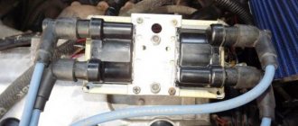
Contactless devices
In appearance there is a great similarity to the previously described devices, but there is no great dependence on the cleanliness and size of the gap in the contact group, and the characteristics are much better than contact ones. Some cars do not have them at all, since control impulses come from special sensors. The main link of the system is an electronic commutator; it outputs a pulse to the coil.
The photo shows an electronic switch for the VAZ 2108.
Such systems generate significantly higher high voltage, which makes it easier to start the engine in the cold season. The absence of burnt contacts does not create additional resistance, which reduces energy losses. Ignition wires must be rated for higher voltage. They are distinguished by color, red belongs to the usual ones, and blue or black are intended for greater tension. To suppress radio interference they have a damping resistance .
The photo shows wires for cars of the VAZ 2108 family.
Both systems also require a distributor cap and rotor . Then everything happens in the same way as with the contact block. Keep in mind that the cover and rotor sometimes fail. They must not be damaged in the form of cracks; the rotor must have damping resistance. The electronic switch requires its own fuse .