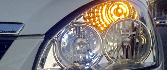
What to do if the turn signals and emergency lights on a VAZ-2110 do not work
Domestic VAZ 2110 model cars are deservedly considered trouble-free. Nevertheless, even in them, certain minor breakdowns sometimes occur. For example, the emergency lights and turn signals often stop working, less often - only one thing. The lights either do not light up at all or, on the contrary, do not turn off. Experienced owners of "ten", as a rule, know very well what to do in such situations, but novice drivers often do not know how to solve the problem. Let's close this gap and figure out what to do if not a single turn signal is functioning and the emergency lights have failed.
Logical conclusion
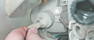
If you are not looking for simple ways, you can try to disassemble the relay itself and check what is wrong with it. Perhaps the movable plate has become sour or the contact has come loose. Since the part is small, you need to be very careful not to bend anything. Using a small soldering iron and some fine-grit sandpaper, you can bring the relay back to life and gain valuable repair experience in the process.
Replacing the VAZ-2110 turn relay is quite simple and quick. There is absolutely nothing complicated, so it makes sense to do such work yourself. It does not require you to have any knowledge of electrical engineering. The relay itself may “fail” if its time is approaching. When the first signs of a malfunction appear, such as intermittent relay failure, altered click frequency, etc., it is better to stock up on a spare part in advance. This way, if necessary, you can immediately replace the VAZ-2110 turn signal relay.
Features of the scheme
The electrical circuit of the VAZ-2110 turn signals includes:
- lantern bulbs, six in total;
- two indicators installed on the dashboard;
- emergency button;
- Understeering's shifter;
- power supply;
- circuit breakers;
- interrupt relay.
The last two elements, responsible for the turn signal, are located nearby - in the mounting block. This unit is installed in the cabin, to the left of the steering wheel. It is closed by a decorative flap, to access which you just need to press the latch located above.
The emergency lights operate in parallel with the turn signals. Their wires are connected by the terminals of one block. It is from this that the veins go to the button that switches the general lighting devices to a mode signaling a breakdown that has occurred on the road. You need to know about this feature of the circuit when starting to search for the reasons for the failure of the lights. The problem is that a faulty VAZ-2110 emergency warning button often causes the turn signals to fail.
Features of replacing standard turn signals with LED ones
- you dismantle old turn signals;
- install new LEDs;
- connect them according to the standard circuit;
- turn on the switch and find that either the turn signals do not work, or they blink at double or even triple the frequency.
We will not answer the question: why does this happen and go into detailed electrical details of the operation of the turn relay on your motorcycle, but will consider the main methods for eliminating this malfunction.
Installing Shunt Resistors
The easiest way to make the turn signal relay “see” a load similar to conventional lamps is to bypass the LEDs with powerful (at least 20÷25 W) resistors with a nominal value of 10÷20 Ohms so that the turn signals blink in accordance with GOST. The following types of resistances are suitable for this:
- SQP-20 in a cast cement case (cost 20÷40 rubles);
- AH-25, in which the body is made of metal with special holes for fastening (120÷140 rubles);
- PEV-20 in ceramic version (100÷150 rubles).
One resistor is connected in parallel to each group of direction indicators (right and left), that is, you need to purchase 2 of them.
Disadvantages of this method:
- Since a large current flows through the shunt resistors, the energy-saving properties of the new turn signals are reduced to zero.
- Cement resistors do not tolerate vibration well and will not last long on a motorcycle.
- The cost of metal products is comparable to the price of a new electronic turn signal relay.
Replacing the standard turn signal relay with an electronic one
From a technical point of view, the most correct way to install LED turn signals is to replace the standard electromechanical relay with an electronic one. The peculiarity of the operation of this device is that the direction indicators blink at a certain strictly specified frequency (regardless of the connected load). Now there are a large number of such devices on the market from various ones, “Tirol”, “Feelwind”, “Vbestlife”, “Catuo”). Depending on the brand and electrical circuit of the motorcycle, it may have a relay with two or three contacts. To avoid the question of how to connect a turn signal relay, purchase an electronic device with the required number of contacts. Now both types of these products are on sale, so replacing and installing new relays will not present any particular difficulties. Price for such products: 250÷350 rubles.
Attention! Before buying an electronic relay, install LED turn signals and perform a test run. If the turn signals work and flash at a normal frequency, then your motorcycle was originally equipped with an electronic relay and there is no need to replace it
Modification of an automobile turn signal relay
For those who like to do homemade things, or if there are difficulties in purchasing an electronic relay in your region, it will not be difficult to make it from a regular automotive turn signal relay with three contacts (marked with the index “495.3747” and today costs 180÷240 rubles) . Below is an electrical diagram of the product itself and its connection:
Upgrade algorithm:
- using a screwdriver, carefully remove the plastic casing of the relay;
- on the circuit board we find a soldered microcircuit;
- we determine the soldering location of leg No. 7 (it is easy to determine, since there is a dot on the body above leg No. 1);
- turn the board over and use a knife to scratch the conductor coming from this leg on the board;
- the relay is ready for installation and further operation with LEDs.
Attention! If, after turning on, the turn signal blinks with too high a frequency, then it is necessary to replace the capacitor C ₁ (instead of the 2.2 µF capacitor installed in the board, install 4.7 µF). Since the current flowing through the LEDs is small, the relay contacts will burn little, and the homemade relay will last quite a long time
In order for the manufactured product to work correctly, install a set of four LED turn signals at the same time
Since the current flowing through the LEDs is small, the relay contacts will burn little, and the homemade relay will last quite a long time. In order for the manufactured product to work correctly, install a set of four LED turn signals at the same time.
The simplest faults
When only one light bulb does not want to work, then most likely the problem lies there. A burnt-out element should be replaced with a suitable one. The turn signal indication mounted on the instrument panel will confirm the suspicion. Look at it - if the blinking is too frequent, then it is definitely a light bulb. When installing a new one, make sure that its power meets the manufacturer's requirements. If this point is ignored, then there is a risk that the alarm devices will not work properly in the future.
When neither the right nor the left turn signal of the VAZ-2110 turns on, and also does not respond to the activation of the emergency lights, then it is worth suspecting that the fuse has blown. It is located, as previously noted, in the mounting block. The number of the protective device is F16. Inspect the element and especially carefully examine its fuse-link.
Messages 5
1 Topic by sanay1605 2015-12-31 16:15:42
- sanay1605
- New member
- Inactive
- Registration: 2015-12-31
- Messages: 7 Thanks : 1
- Car: VAZ 2110
Topic: Resolved: The relay clicks, but the turn signals do not work. Hazard light - fuse is on
I have a problem and have been struggling with it for three days now. Initially, it was. When the turn signals are turned on, the relay makes clicks but nothing blinks, and when the emergency lights are turned on, the fuse that turns on the tidy was on and one turn signal on the fender blinked dimly. I thought the relay was replaced, it didn’t work, I thought the tracks were burned out, I opened the whole unit, changed the fuse, changed the emergency button. All to no avail. Who came across it?
2 Reply from kosmos 2015-12-31 19:33:14 (2015-12-31 19:35:19 edited by kosmos)
- cosmos
- Blocked
- Inactive
- Registration: 2014-05-17
- Posts: 2,021 Thanks : 406
- Auto: 2111 - 1.5 -16v
Re: Resolved: The relay clicks, but the turn signals do not work. Hazard light - fuse is on
There's a short circuit somewhere. What kind of lamps are in the turn signals - LED or regular? Remember what you did and when! Look for a short circuit either in the wires, or near the turn signals, or directly in them. Pull out the lamps from the turn signals one at a time and check that they are turned on, feel the wires, there may be a short circuit in the socket itself in one of the turn signals.
3 Reply from sanay1605 2015-12-31 19:52:53
- sanay1605
- New member
- Inactive
- Registration: 2015-12-31
- Messages: 7 Thanks : 1
- Car: VAZ 2110
Re: Resolved: The relay clicks, but the turn signals do not work. Hazard light - fuse is on
Well, he didn’t do anything, that’s for sure. Before this, the car was parked in the garage, the humidity was high, that’s what else I can say
4 Reply from kosmos 2015-12-31 19:55:59
- cosmos
- Blocked
- Inactive
- Registration: 2014-05-17
- Posts: 2,021 Thanks : 406
- Auto: 2111 - 1.5 -16v
Re: Resolved: The relay clicks, but the turn signals do not work. Hazard light - fuse is on
If there’s humidity, that means we’re looking at all the turn signal sockets, the wires also rot like crazy in humidity, especially where they’re singed on the floor, for example, there’s obviously a short somewhere. The turn signal system is insanely simple, so there will be a problem!
More serious problems
If it turns out that nothing happened to the fuse, then you will have to check the relay responsible for the turn signals. It is located in the mounting block in place K3. This electromagnetic breaker sometimes fails. A break in the windings or jamming of the armature may occur here.
Testing a relay is easy. Do this:
- remove the protective casing from the device;
- activate the ignition;
- close the contact group with a small piece of copper wire.
After this, leave the cabin and look at the turn signals. The relay will have to be replaced if the lights start to glow continuously. When it turns out that they are not burning at all, then it is necessary to start ringing the cables and connectors. In the latter, contact is lost very often. Sometimes the leads oxidize, and then the contact resistance increases, which provokes burning. Clean the terminals with a file, a student's eraser, or alcohol. Be sure to make sure that all wires connected to the terminals are securely fastened.
Controls
Not too often, the reason that prevents the turn signals from working is the steering column switch.
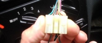
In this case, there are usually no problems with emergency lights. To check its serviceability, you will have to suffer a little. First of all, remove the casing covering the steering column. Here you will find a connector that connects the wires leading to the switch. The blue and red cables must be connected directly. Simply unplug the block and insert a jumper (such as tweezers) into the corresponding terminals.
Next, get out of the cabin and see if the turn signal is working properly. If yes, then you will have to change the switch; failures in it are usually purely mechanical and it is unrealistic to eliminate them - the design does not provide for it. When nothing happens, look further.
In general, there are only two versions left to explain why the turn signal does not work:
- break in the wiring;
- hazard warning button failure.
To check the cables, you need to remove the negative terminal from the battery. Next, starting from the switch, all the veins are inspected (and simultaneously tested with a multimeter). Insulation damage and breaks are repaired. It is advisable to replace unusable sections with a new intact wire, since otherwise the risk of repeated failure cannot be completely eliminated.
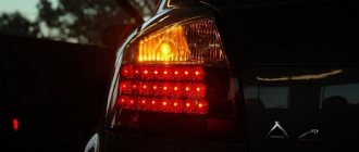
Why don't turn signals and emergency lights work, and what can I do about it?
Turning lights are an integral element of optics in any modern car. Their purpose is to warn other road users that the driver is planning to make a maneuver. For what reasons do turn signals and emergency lights not work, how to check the functionality of optical elements and how to repair them. We will talk about this below.
The nuances of turning on running lights
The basic requirements regarding installation, technical parameters and connection of navigation lights are listed in paragraph 6.19 of GOST R 41.48-2004. In particular, the electrical functional circuit of the DRL must be assembled in such a way that the running lights turn on automatically when the ignition key is turned (the engine starts). In this case, they should automatically turn off if the headlights are turned on.
Clause 5.12 of this standard states that headlights (FGS) should be turned on only after the lights are turned on, with the exception of short-term warning signals. When connecting DRLs yourself, this feature must be taken into account.
Correct connection of DRLs is not limited to a well-thought-out functional diagram. It's time to think about the stabilization unit for LEDs. In the running lights themselves, resistors act as a current limiter; however, due to voltage drops, resistors cannot limit the current to the same level. That is why a voltage stabilizer in the running lights connection circuit is extremely necessary. Otherwise, the service life of LED DRL modules is significantly reduced due to constant changes in on-board voltage. Some car enthusiasts claim that it is possible to connect running lights without a stabilizer.
However, this statement is easy to dispute. The fact is that with each voltage surge, more than 12 V appears on the LED module, the forward current through the LEDs exceeds the nominal value, which leads to overheating of the emitting crystal. The brightness of the LEDs decreases, such DRLs will no longer be able to fulfill their immediate task - to warn oncoming drivers from afar, and over time they will begin to flicker and fail.
For ease of understanding, the circuits below are shown without using a stabilizer.
Reasons for failure of turn signals and emergency lights
As you know, the circuit of direction indicators and hazard warning lights is tied, since both functions are performed by the same headlights. If for some reason the hazard lights are working, but the turn signals are not, or neither the turns nor the warning lights are on, this can lead to an emergency situation on the road.
For what reasons did these elements stop working:
- Fuse failure is one of the most common problems. If the car is additionally equipped with a relay that is responsible for the operation of these optical elements, then the problem may lie there. Depending on the car model, the relay may be located separately from the main fuse block; use the diagram to find the failed part.
- Short circuit in the system. Because of this, when turning on the turning lights, the emergency lights turn on or the optics do not respond to the driver’s commands at all. To diagnose the problem, you will need a tester, as well as the skills of an electrician.
- Failure of the lighting source. In other words, the light bulb has burned out.
- Open circuit. This problem is relevant for many car owners of older cars. If the wires are laid in a place where there are moving elements, then over time it will fray and lose its insulation, which will generally lead to damage to the electrical circuit.
- Failure of a button or steering column switch. In this case, it is necessary to carry out more thorough diagnostics of the switch, as well as the connection button.
Messages 16
1 Topic by AMORAL 2015-10-28 17:40:10
- AMORAL
- New member
- Inactive
- From: Tula
- Registration: 2014-01-25
- Messages: 46 Thanks : 3
- Auto: 2112
Topic: Front right turn signal does not work, there is voltage, I changed the lamp
Hi all! Maybe a trivial problem, but still. Background, at first the right side began to blink rapidly, but all three turn signals worked. A week later the front one, which is in the headlight, stopped working. The voltage was measured - yes. The light bulb is normal, but just in case I bought a new one, nothing has changed. Complete stupor, I don’t know where to dig, because I expected that there was no voltage. Maybe someone has encountered this and can give some good advice?
2 Reply from Slag 2015-10-28 19:28:04
- Slag
- Participant
- Inactive
- From: Dnepropetrovsk
- Registration: 2014-04-23
- Messages: 146 Thanks : 43
- Car: 2111 1.5 16kl. 2002
Re: The front right turn signal does not work, there is voltage, I changed the lamp
Accelerated blinking of the turn signals means the resistance in the circuit has dropped. If all the lamps are working, then it is worth looking at the lamp bases and lamp seats for contact oxidation. There is contact, but not sufficient.. Perhaps the contact under the lamp in the headlight has oxidized..
3 Reply from AMORAL 2015-10-29 00:20:47
- AMORAL
- New member
- Inactive
- From: Tula
- Registration: 2014-01-25
- Messages: 46 Thanks : 3
- Auto: 2112
Re: The front right turn signal does not work, there is voltage, I changed the lamp
Accelerated blinking of the turn signals means the resistance in the circuit has dropped. If all the lamps are working, then it is worth looking at the lamp bases and lamp seats for contact oxidation. There is contact, but not sufficient.. Perhaps the contact under the lamp in the headlight has oxidized..
There were no visible oxides, but just in case I cleaned everything up, there were no changes. PS There are LED lights installed at the rear, could something like this start due to them? But, I repeat, only the right front turn signal does not work.
4 Reply from kosmos 2015-10-29 03:50:51
- cosmos
- Blocked
- Inactive
- Registration: 2014-05-17
- Posts: 2,021 Thanks : 406
- Auto: 2111 - 1.5 -16v
Re: The front right turn signal does not work, there is voltage, I changed the lamp
There were no visible oxides, but just in case I cleaned everything up, there were no changes.
Have you tried changing your contacts? There is voltage, but the contact does not reach the lamp.
There are LED lights at the rear, could they cause something like this?
Maybe this is the reason for the rapid blinking, but the turn signal should be on! There's just no contact.
5 Reply from AMORAL 2015-10-30 01:32:50
- AMORAL
- New member
- Inactive
- From: Tula
- Registration: 2014-01-25
- Messages: 46 Thanks : 3
- Auto: 2112
Re: The front right turn signal does not work, there is voltage, I changed the lamp
There were no visible oxides, but just in case I cleaned everything up, there were no changes.
Have you tried changing your contacts? There is voltage, but the contact does not reach the lamp.
There are LED lights at the rear, could they cause something like this?
Maybe this is the reason for the rapid blinking, but the turn signal should be on! There's just no contact.
Podginal. I'm already scratching my head about what the reason is. Friends are also shocked how this can happen. Everyone says that they have never encountered anything like this. That's why I decided to write here
As for the LED lights, I’ve had them installed for about half a year, before that everything was ok, and only one side started blinking - the right side. And then the right front turn signal stopped working. Everything is fine with the left side, it blinks as it should. Some kind of mysticism.
6 Reply from klimashov.roman 2015-10-30 08:15:23
- klimashov.roman
- Connoisseur
- Inactive
- From: Kasimov
- Registration: 2014-04-21
- Messages: 743 Thanks : 143
- Car: GAZelle 33023 dv 405.22, 2.4 16kl 140hp
Re: The front right turn signal does not work, there is voltage, I changed the lamp
Maybe you should look towards the turn switch, there are no oxides there
7 Reply from Slag 2015-10-30 10:01:18
- Slag
- Participant
- Inactive
- From: Dnepropetrovsk
- Registration: 2014-04-23
- Messages: 146 Thanks : 43
- Car: 2111 1.5 16kl. 2002
Re: The front right turn signal does not work, there is voltage, I changed the lamp
And in the emergency light button, it seems like the chain of all the turn signals goes through it...
8 Reply from AMORAL 2015-10-31 12:39:32
- AMORAL
- New member
- Inactive
- From: Tula
- Registration: 2014-01-25
- Messages: 46 Thanks : 3
- Auto: 2112
Self-diagnosis of car lighting devices
There are several situations in which you can determine that optics need diagnostics:
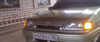
- The turns do not flash, but light up. Such a malfunction indicates the failure of the relay, in particular, we are talking about its electromagnetic component. The electromagnet itself could close in one of the positions, as a result of which it cannot return to its initial state.
- The turning lights flash very quickly or very slowly. In this case, the problem may lie not only in the relay. In some cases, this type of malfunction occurs when the driver uses inappropriate lighting sources. So when purchasing new light bulbs, you need to make sure that they correspond to the rating set by the car manufacturer.
- The optics don't work at all. That is, the turning light bulbs do not flicker, and the corresponding indicators on the dashboard also do not light up. In addition, there are no characteristic clicks that appear when turning on the turning lights. With such symptoms, there can be many reasons for the problem; we will tell you more about their diagnosis below (the author of the video is the Steel Horse channel).
As for diagnostics, it is performed in several stages:
- First of all, you need to make sure that all sensors and indicators on the device are working. If they do not function, then it is necessary to diagnose the safety devices.
- If all devices are operating in normal mode, then you next need to turn on the light alarm button and diagnose all light sources in the headlights. That is, check the front, rear, and side (if any) lights.
- If the alarm does not function when activated, you need to check the functionality of the relay, and also check the power supply at the terminals. To do this, remove the relay from its mounting location, and then, using a test light, connect one of its contacts to the installation site (to the positive), and the other to the car body or battery. There is no need to turn on the ignition. If there is no power, then most likely the reason lies in a failed safety device, a broken hazard warning button, or a damaged electrical circuit. Also, the essence of the problem may lie in poor contact in the connecting plugs.
- If there is a plus on the contacts, then try shorting the two relay terminals using copper wiring. If all electrical circuits, as well as the connection plugs, are working properly, then all turn signals should light up. In this case, the fault must be looked for in the relay.
- If the lights do not light up after the steps you have performed, then most likely the cause of the malfunction lies in the emergency light control button. However, in practice this happens quite rarely; there is often a short circuit in the circuit. By the way, it is a short circuit that can lead to a breakdown of the relay, therefore, before replacing the failed element, you need to eliminate the short circuit.
- If the emergency signal is functioning, this indicates that the safety devices and relays are working; accordingly, you need to start diagnosing the button itself. First of all, you need to diagnose the positive terminal, as in the case of checking the relay, while the ignition, as well as the hazard warning button, must be activated. If the diagnostics showed that there is no plus, this indicates that the button itself needs to be checked in more detail. Remove it from its seat and check the connection circuit. If there is no power, then you need to look for a break in the wiring from the tidy to the button itself. If there is power, then it will be necessary to short-circuit the terminals at the installation site, the ignition does not turn off, after which the direction indicators must be activated (on either side). When the lighting sources are turned on, the control button must be replaced, but if there is no power, then you need to check the power in the emergency relay. If there is no power, the problem most likely lies in a break in the connecting electrical circuit from the control key to the block with safety devices.
Video “Budget option for repairing a steering column switch”
The video below presents an inexpensive option for repairing the steering column switch in a Peugeot car (the author of the video is the EzjikOnline channel).
The cause of non-functioning electrical equipment in the car (for example, fuel pump, heated seats, heated windows, power windows, etc.) may be a faulty relay. Let's look at a simple way to test a car relay for functionality with your own hands.
Connection diagram for 4 and 5 contact relays:
To check the relay you need (all relay contacts are labeled, and the power contacts usually have a yellowish tint):
- Apply 12 V voltage (for example, from a battery) to the terminals of the relay coil winding (control contacts 85 and 86).
- Measure the resistance (multimeter in ohmmeter mode) between the power terminals (30 and 87).
If the relay is working, then when voltage is applied there will be a click and the resistance will become close to zero (infinitesimal). Otherwise, the relay is faulty and must be replaced.
Feature of checking a 5-pin relay : contacts 30 and 88 must be closed, and when voltage is applied to the control contacts (85 and 86) they must open. Otherwise the relay is faulty.
The relay testing process is also presented in the video:
Let us remind you that another cause of electrical equipment malfunction in the car may be a broken wiring or short circuit. You can also determine the cause using a multimeter.
Key words: universal article
Do-it-yourself repair of direction indicators and hazard alarms
If the turns disappear, as well as the car’s emergency signal, then you can try to solve this problem yourself:
- If the safety element and relay break down, the failed parts must be replaced. If the reason lies in a short circuit, then before replacing it is necessary to check all electrical circuits in which it could occur. Only after the cause of the short circuit and power surges has been eliminated, the devices need to be changed.
- If the hazard warning button is faulty, you just need to replace it. We have already talked about how to diagnose this part.
- As for electrical circuit diagnostics, it is carried out using a tester. If damaged sections of the wire are identified, they must be replaced. When laying them, make sure that the wiring does not come into contact with moving body elements. It is also recommended to additionally insulate new wires to increase the reliability of the insulation.
- If the reason is the light bulbs, then all burnt out light sources must be replaced. In the front and rear headlights, the lamps are changed by removing the protection from the headlights, disconnecting the power circuit from the lamp, as well as unscrewing the light source from the seat and replacing it with a new one. If the lamps in the side headlights do not work, then, as a rule, to dismantle the lighting sources, the lamp itself must be pryed off with a screwdriver, then disconnect the power cord and remove the device.
- If the reason lies in the steering column switch, then this device needs to be disassembled and checked. As a rule, the cause of switch failure is poor contact or abrasion. In this case, the failed switch is replaced with a new one. As for the contacts (no matter where - on connections or buttons), it is advisable to clean them.
- You should also check all the plugs and connectors, because it is quite possible that the problem is poor contact on them. Acidified contacts must be cleaned with a wire brush or sandpaper. If the contacts are burnt out, they will need to be replaced.
Instructions for making a turn signal extension
Scheme for organizing lazy turns
You can build a turn signal extension at home if necessary. You will need a turn signal diagram, which you can download from the Internet, make yourself, or take a ready-made one on our website. In accordance with the scheme, the main elements for its implementation are selected.
Brief instructions on how to make a turn signal extension yourself:
- First you need to find a case; alternatively, you can use the packaging from the magnetic head of an old tape recorder. In order for yellow or red turn signals to flash at longer intervals, you must follow the pattern exactly. In accordance with it, the main elements are soldered.
- When the circuit is soldered, the partitions should be removed from the case, but it is better to leave the ribs on the end parts; they will be needed to secure the board. If necessary, additional holes for connectors can be made in the housing.
- The board is mounted in the case.
- The case itself is closed; for a more reliable fixation, it can be treated with glue at the joints.
- The following work is carried out in the salon. You need to get to the fuse box where the corresponding relay is installed. The panel from this relay can be removed, and wires are then connected to its connector. The black cable goes to ground, the green cable with a blue stripe goes to the ignition, the black-blue cable is the left turn, and the black-red cable is the right turn.
- The device itself can be fixed directly to the relay using glue or double-sided tape.
Troubleshooting if turns do not work, even if you do not have special knowledge.
Checking the serviceability of the turn relay.
And so let’s look at what to do if the turns of a front-wheel drive VAZ, except for the 2170 Priora, do not work. The operation and troubleshooting of which was discussed in the article “Prior Turning Relay”.
First, make sure that the measuring instruments and control lamps on the instrument panel are working. If they do not work, then check the fuse.
If the devices are working properly, turn on the hazard warning button and check that all the lamps in the direction indicators are blinking. This will allow you to divide the circuit into two parts and speed up troubleshooting.
If the alarm does not work when turned on, then it is necessary to check the serviceability of the turn and alarm relay and the presence of power at its terminal 49. The pin designation is marked on the bottom of the relay, next to the contact legs.
We remove the relay, which is marked in the form of a triangle on the top of the case, from the mounting block, and in the vacated socket, using a test paw, check for the presence of a plus on pin 49. We connect the test lamp to the ground or minus of the battery, and with the other end we touch pin 49, when If the hazard warning button is on, you do not need to turn on the ignition. Lack of power indicates a faulty fuse, alarm button or broken wires, contact tracks of the mounting block and poor contact in the connectors.
If there is a plus on the terminal, then connect terminals 49 and 49A with a copper wire. If the connecting wires and connectors are in good condition, all the direction indicator lamps should light up. This indicates that the turn signal and light signaling relay is faulty. If the lamps do not light up, but there is a plus on pin 49, then there may be a short circuit in the signal lamp circuit and the fuse has blown. A short circuit can also cause the relay to fail. In this case, check the serviceability of the fuse, and if it blows, eliminate the short circuit in the signal lamp circuit.
Checking the hazard warning button.
If the hazard warning lights are working, then the turn signal and hazard warning relays are working properly, but the fault may be in the hazard warning light button. First, check the plus, as described earlier at pin 49 of the relay, with the hazard warning button off and the ignition on.
If there is no plus, then you need to check the serviceability of the alarm button. To do this, you need to remove the button from the socket by prying it off with a thin screwdriver or remove the instrument panel visor. In the contact connector of the button, use a test lamp to check the presence of power at pin 2 (the numbering of pins on the button near the contacts) with the ignition on. If there is no power, repair the broken wire from the instrument panel to the button. If there is power, connect pin 2 to pin 5 in the button socket, with the ignition on, and turn on the direction indicators of either side. If the warning lights on this board light up, replace the faulty hazard warning button.
If the warning lights do not light up, then, without removing the jumper from the hazard warning button block, connect pins 49 and 49A with a copper wire in the relay socket, then check the power at pin 49A of the turn switch. To do this, remove the steering column cover and the connecting connector from the turn switch. You can also remove the switch itself to determine the pin numbers that are marked on its lower part next to the contact legs. This is not difficult to do by squeezing the latches on the sides of the switch and pulling it to the side. If the circuit from the relay to the switch is in good condition, the indicator lamp will start to light. If the control lamp does not light, then repair the break in the wire from the mounting block to the turn signal connector.
Tips for motorists
The VAZ-2110 turn indicators include six lamps located on the right and left sides of the car, two light signaling lamps on the instrument panel, a turn signal breaker relay and a fuse located in the mounting block, and controls all this under the steering switch.
The hazard warning lights work together with the direction indicators , and all wiring goes through the plug block of the hazard warning light button. Therefore, malfunctions that occur on this button also lead to failures in the direction indicators.
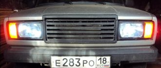
The most common malfunction of turn signals on a VAZ 2110 is the burnout of one of the lamps, which should have worked after it was turned on. A warning lamp will notify you of this. Its blinking frequency will increase exactly twice, which will be clearly visible to the driver who glances at the instrument panel. When replacing a burnt-out lamp, pay attention to its power; you need to replace it with exactly the same one, otherwise the light alarm will not work normally.
If the turn signals do not turn on on either the right or left side of the car. Then you will have to open the mounting block and check fuse F16. If this fuse is intact, pay attention to the relay breaker K3, it may have failed. You can check it as follows. You need to open the relay cover and, with the ignition on, bridge two contacts located perpendicular to each other using a piece of wire. If the turn signal lamps start to light without blinking, then this relay will have to be replaced, as it is faulty. But if the lamps do not light, then you will need to check the wires and plug blocks for lack of contact.
When turning on the turns, the fuse blows.
Another malfunction of the direction indicators is the fuse blowing when the indicators of one of the sides are turned on. To quickly identify a malfunction, turn on the hazard warning lights. The signal lamp in a circuit that has a short circuit will not light up or will burn at full intensity. A sign of a short circuit in the signal lamp circuit can be a buzzing sound from the turn signal relay when the indicators are turned on. To facilitate troubleshooting when the VAZ direction indicators do not work, use the diagrams below.
About fuses and relays
The machine is equipped with a fuse box in which they are installed in large quantities. Each of them is responsible for one or another function. If the fuse blows, the turn signal or lights may not work. This, of course, applies to absolutely all electronic systems, but these are the ones we are interested in.
The fuse is used for overload protection. If there is a problem in the circuit, say the voltage is too high, the fuse blows. Consequently, the circuit is washed out on it, and the voltage does not flow further. It turns out that the same turn signal will not function without a fuse, which is quite logical.