Remove the cylinder head and then the gasket.
Make necessary repairs and reassemble. When assembling, we recommend paying attention to the following nuances:
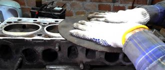
- Check the planes of the cylinder block and head.
Measure the length of the cylinder head mounting bolts; if it exceeds 95 mm, they should be changed.
The tightening torque for the top plate bolts is 10 Nm. The tightening sequence is shown in the photo below.
The tightening force of the valve cover bolts is 3-4 Nm. Also be sure to apply sealant as shown below.
The process of replacing the cylinder head on 16-valve VAZ 2110, 2111, 2112 is clearly shown in this video:
Disassembly and assembly of the cylinder head of VAZ 2110, VAZ 2111, VAZ 2112, Lada Ten
We carry out work when replacing the head gasket, repairing the valve mechanism and the head itself, as well as when completely disassembling the VAZ 2110 engine.
Disconnect the negative cable from the battery and drain the coolant. We disconnect the throttle drive cable, the exhaust pipe, the ground wires from the left end of the head, the connectors of the coolant temperature and oil pressure sensors, and the hoses of the cooling system outlet pipe. We remove the receiver with the throttle assembly of the VAZ 2110, the intake manifold, the fuel rail with the VAZ 2112 injectors and tubes, the cylinder head cover, the rear support bracket of the power unit, the camshaft pulleys and the rear timing belt cover of the VAZ 2112. You can dismantle the head without removing intake and exhaust manifolds. In the disassembly version shown, the collectors have been removed for clarity. For all of the above dismantling operations, see the relevant sections.
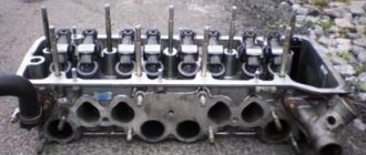
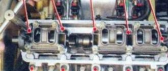
Use a 10mm hex to unscrew the ten bolts securing the cylinder head. We take out the bolts and washers.
We carry out further disassembly of the head on a workbench. We dismantle the camshaft bearing housing, remove the camshafts and take out the hydraulic tappets (see Replacing the hydraulic valve tappets of the VAZ-2112 engine).
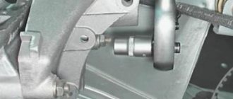
Using a 13mm wrench, unscrew the two nuts securing the outlet pipe of the VAZ 2111 cooling system.
Using a 21 key, unscrew the coolant temperature indicator sensor.
We dry out the valves, remove the springs with plates (see Replacing oil seals for VAZ-2112 engine valves). To support the valves of the VAZ 2112 when compressing the springs, we place a wooden block under their plates (from the bottom of the head).
conclusions
Please note that upon completion of the work, it is necessary to install a new cylinder block gasket, carry out all work in strictly the same order as removal, and also pour new coolant into the system and check all connections for leaks.
Despite the fact that this work is quite difficult due to the dismantling of numerous pipes, pads and threaded connections, it is very doable with your own hands, you just need to read our article very carefully and you can get to work without fear.
Disassembly and assembly of the cylinder head of VAZ 2110, VAZ 2111, VAZ 2112, Lada Ten
We carry out work when replacing the head gasket, repairing the valve mechanism and the head itself, as well as when completely disassembling the VAZ 2110 engine.
Disconnect the negative cable from the battery and drain the coolant.
We disconnect the throttle drive cable, the exhaust pipe, the ground wires from the left end of the head, the connectors of the coolant temperature and oil pressure sensors, and the hoses of the cooling system outlet pipe.
We remove the receiver with the throttle assembly of the VAZ 2110, the intake manifold, the fuel rail with the VAZ 2112 injectors and tubes, the cylinder head cover, the rear support bracket of the power unit, the camshaft pulleys and the rear timing belt cover of the VAZ 2112.
You can dismantle the head without removing the intake and exhaust manifolds. In the disassembly version shown, the collectors have been removed for clarity. For all of the above dismantling operations, see the relevant sections.
Using a 10mm hexagon, unscrew the ten bolts securing the cylinder head. We take out the bolts and washers.
Remove the cylinder head.
. and its gasket.
We carry out further disassembly of the head on a workbench.
We dismantle the camshaft bearing housing, remove the camshafts and take out the hydraulic tappets (see Replacing the hydraulic valve tappets of the VAZ-2112 engine).
Using a “13” wrench, unscrew the two nuts securing the outlet pipe of the VAZ 2111 cooling system.
Remove the pipe from the studs.
Using a 21 key, unscrew the coolant temperature gauge sensor.
We dry out the valves, remove the springs with plates (see Replacing oil seals for VAZ-2112 engine valves).
To support the valves of the VAZ 2112 when compressing the springs, we place a wooden block under their plates (from the bottom of the head).
We remove the valves from the guide bushings of the VAZ 2110 cylinder head.
Remove the oil seals from the guide bushings and the spring support washers.
We assemble and install the cylinder head in the reverse order.
Before installation, we clean the surfaces of the cylinder block and head 2112 from the remains of the old gasket, dirt and oil.
We lubricate the valve stems of the VAZ 2111, the holes of the guide bushings, the holes for the hydraulic pushers and the new oil seals with engine oil.
We remove oil and coolant from the threaded mounting holes of the cylinder block.
We install the new gasket and cylinder head onto the block using two centering bushings.
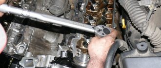
We install the fastening bolts and tighten them in three steps according to the diagram (see Fig. “Procedure for tightening the bolts of the VAZ 2112 cylinder head”):
first step – tightening 20 Nm (2 kgf.m)
second step – turn 90°
the third step is a 90° turn.
The head fastening bolts may only be reused if they have been extended to a length of no more than 95 mm. If it is larger, replace the bolt with a new one.
Main signs for dismantling the cylinder head
The manufacturer did not provide any regulations for replacing auxiliary parts of the cylinder head, but there are some signs that will still require dismantling it.
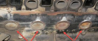
- Presence of mechanical traces on the cylinder head.
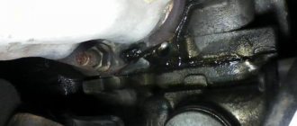
- The presence of engine oil or antifreeze leaks at the junction of the cylinder head with the block.
- If white steam comes from the exhaust pipe , this will mean that antifreeze has got into the cylinders and there is no way to do this without removing the cylinder head.
- Emulsion foam on the expansion tank cap indicates exhaust gases entering the cooling system.
- in the coolant - this indicates that the system is not tight.
- on the engine oil dipstick , which tells us that there are traces of antifreeze (antifreeze) in the oil. The work will require removal of the cylinder head.
Design and repair of the cylinder head of the VAZ 2112 engine
Search and find in the section: Engine repair of the VAZ 2112 model
Cylinder head repair step by step, in pictures
Head
1
cylinder block
common to four cylinders, cast from aluminum alloy, with tent-shaped combustion chambers.
The inlet and outlet channels are located on different sides of the block head .
The valves are arranged in a V-shape in two rows: inlet on one side, exhaust on the other. The head has metal pressed onto ceramic valve seats and brass valve guides. The inner diameter of the guide bushings is (7±0.015) mm, the outer diameter (for bushings supplied as spare parts) is 12.079-12.090 mm and 12.279-12.290 mm (bushing increased by 0.2 mm).
Removing the cylinder head of a VAZ 2112 16 valves
The Auto_Repair channel will help you troubleshoot your car yourself.
Replacing the cylinder head gasket. Removal and installation of cylinder head. VAZ 2112 1.5 16v
In this video I will explain in detail about replacing the cylinder
, the reasons why it’s time to change it, the consequences.
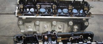
Cylinder head parts : 1 - cylinder head
; 2-intake camshaft; 3 - oil seal; 4 - exhaust camshaft: 5 - camshaft bearing housing: 6. 8 - o-rings; 7 - guide pipe, 9 - block head cover; 10 — bracket for fastening the wiring harness: 11 — plugs; A - distinctive belt of the intake camshaft.
Valves of this design are similar to engine valves mod. 2110, but have a smaller diameter of discs and rods. The inlet valve has a disc diameter of 29 mm, and the exhaust valve has a diameter of 25.5 mm. The diameter of the intake valve stem is (6.9750.007! mm, exhaust - (6.965±0.007) mm.
One spring is installed on each valve. The length of the spring in the free state is 38.19 mm, under load (240±9.5! N [(24.5±0.98) kgf] should be 32 mm. and under load (55027.5) N [(56.1± 2.8) kgf] -24 mm,
The valves are driven by camshaft cams through cylindrical hydraulic pushers located in the guide holes of the cylinder head along the axis of the valve holes. Hydraulic tappets automatically eliminate the clearance in the valve mechanism, and therefore, when servicing the vehicle, there is no need to check and adjust the clearance in the valve mechanism.
Oil for the operation of hydraulic pushers is supplied from the lubrication system through a vertical channel in the cylinder block to a channel in the cylinder head near the 5th mounting bolt, and then through the upper channels made below the lower plane of the bearing housing. Oil is supplied through the same channels to lubricate the journals of the camshafts. A check ball valve is located in the vertical channel of the cylinder head, which prevents oil from draining from the upper channels after stopping the engine.
The valves are driven by two camshafts: intake and exhaust. The shafts are cast from cast iron and are equipped with five support journals, which rotate in sockets made in the cylinder head and in one common camshaft bearing housing. To increase wear resistance, the working surfaces of the cams and the journal for the oil seal are whitened to distinguish the intake camshaft from the exhaust camshaft, on the intake The shaft near the first support has a distinctive belt A.
The shafts are kept from axial movements by thrust collars located on both sides of the front support. The front ends of the camshafts are sealed with self-clamping rubber seals. The rear holes located along the axis of the shafts in the cylinder head and bearing housing are closed with rubberized caps.
Checking the technical condition and repairing the cylinder are similar to those described for the engine mod. 2110.
For repair
You will need: a device for compressing valve springs, a device for pressing out and a mandrel for pressing in oil seals, a 10 mm socket wrench, a 10 mm hexagon, a screwdriver, tweezers
1.Remove
cylinder head from the engine
2.Unscrew the coolant temperature gauge sensor from the rear end of the cylinder head.
3.Unscrew the emergency oil pressure drop warning lamp sensor from the camshaft bearing housing.
4.Unscrew the two mounting bolts and remove the fuel pipe bracket.
When is replacement required?
The primary issue that concerns car owners is the frequency of replacing the element. Even if the unit is not disassembled, the seal has a certain service life.
In general, the lifespan of a gasket directly depends on the quality of the material used in its manufacture. Also, the frequency of replacement is affected by the intensity of use of the vehicle.
As we have already noted, replacement should be performed when disassembling the BC head, or when primary signs of wear appear.
Removing and installing the cylinder head of VAZ 2112 and 21124 (16V)
The engine cylinder head can be removed as an assembly or after partial disassembly (remove the camshafts). Both options are shown on engine 21124 (1.6i). On the 2112 (1.5i) engine, the work is performed in a similar way (see text for details).
1. Drain the coolant from the engine (see “Coolant - replacement”).
2. Remove the rear timing belt cover (see “Camshafts of engines 2112 and 21124 (16V) - removal and installation”).
3. Remove the cylinder head
(see “
Cylinder head for engines 2112 and 21124 (16V) - removal and installation”).
If the cylinder head is removed for subsequent repairs, it is better to partially disassemble it before removal:
a) remove the camshafts (see “Camshafts of engines 2112 and 21124 (16V) - removal and installation”);
b) remove the hydraulic pushers from their seats (see “Hydraulic valve pushers for engines 2112 and 21124 (16V) - removal and installation”);
c) remove the fuel rail (see "Fuel rail of engine 2112 (1.5i 16V) - removal, disassembly, assembly and installation", or "Fuel rail of engine 21124 (1.6 16V) - removal, disassembly, assembly and installation" );
d) remove the camshaft position sensor (see “Camshaft position sensor - check and replacement”);
e) disconnect the upper mounting rod of the power unit from the engine bracket (see “Upper mounting rod of engines 2112
and 21124 (16V)").
If disassembling the cylinder head is not required (for example, to replace the cylinder head gasket), it should be removed together with the camshafts, bearing housing, fuel rail, oil pressure and camshaft position sensors.
4. Disconnect the upper mounting rod of the power unit from the cylinder head bracket (see “Upper mounting rod of engines 2112 and 21124 (16V)”).
5. Using a 13 mm socket wrench, unscrew the three nuts securing the rod bracket.
Recent Entries
BMW 530e Hybrid revised for 2022
The BMW 530e PHEV has been updated with a new battery, improved efficiency, lower emissions and increased electric power range. The hybrid BMW 530e was
Watch a plane crash land on a public road, caught on police dash cam
Starman Adventures Is a Big Hit Among Teslas - SpaceX Fans
New deal offers drivers a free car - life-saving brakes for drivers up to £1,600
Categories
Test Drive
Ferrari Portofino 2019 review
Ferrari Portofino. this is a super stallion that you will ride every day Maximums Spectacular gearbox with excellent shift mechanics
Multithumb errors found on this page:
There was a problem loading image https://spike.su/images/clip_image001_8e398289-b8b4-4155-a38a-08478d4757db.jpg There was a problem loading image https://spike.su/images/clip_image001_8e398289-b8b4-4155-a38a -08478d4757db.jpg There was a problem loading image https://spike.su/images/clip_image002_2668e6ed-530f-4e20-b6b2-a57b203df4fe.jpg There was a problem loading image https://spike.su/images/clip_image002_2668e6ed-530f -4e20-b6b2-a57b203df4fe.jpg There was a problem loading image https://spike.su/images/clip_image003_95c96ca5-c350-4871-a9d6-4f4b270efd72.jpg There was a problem loading image https://spike.su/images /clip_image003_95c96ca5-c350-4871-a9d6-4f4b270efd72.jpg There was a problem loading image https://spike.su/images/clip_image004_776f3be9-e1c8-4816-a58d-ceede63568a7.jpg There was a problem loading image https://spike .su/images/clip_image004_776f3be9-e1c8-4816-a58d-ceede63568a7.jpg There was a problem loading image https://spike.su/images/clip_image005_1fd9f520-b654-46c6-a6ae-67306ad3e189.jpg There was a problem loading image https ://spike.su/images/clip_image005_1fd9f520-b654-46c6-a6ae-67306ad3e189.jpg There was a problem loading image https://spike.su/images/clip_image006_77da8e10-586c-4891-878d-8a50ac590350.jpg There was a problem loading image https://spike.su/images/clip_image006_77da8e10-586c-4891-878d-8a50ac590350.jpg There was a problem loading image https://spike.su/images/clip_image007_bee8d762-1aaa-4a86-bd31-cde7aa12d3d9. jpg There was a problem loading image https://spike.su/images/clip_image007_bee8d762-1aaa-4a86-bd31-cde7aa12d3d9.jpg There was a problem loading image https://spike.su/images/clip_image008_9b590463-60d4-4948- 8037-2107c46a25c2.jpg There was a problem loading image https://spike.su/images/clip_image008_9b590463-60d4-4948-8037-2107c46a25c2.jpg There was a problem loading image https://spike.su/images/clip_image009_6eb96bdf- b85d-4381-baee-ae0a1d930cbb.jpg There was a problem loading image https://spike.su/images/clip_image009_6eb96bdf-b85d-4381-baee-ae0a1d930cbb.jpg There was a problem loading image https://spike.su/ images/clip_image010_3ef6b082-344c-49d6-9364-fadd928c6c14.jpg There was a problem loading image https://spike.su/images/clip_image010_3ef6b082-344c-49d6-9364-fadd928c6c14.jpg There was a problem loading image https:// spike.su/images/clip_image011_e3b3e86a-d3c0-45a4-86fc-e73af4a03094.jpg There was a problem loading image https://spike.su/images/clip_image011_e3b3e86a-d3c0-45a4-86fc-e73af4a03094.jpg There was a problem loading image https://spike.su/images/clip_image012_45b82799-e329-4085-828c-794329c697BB.jpg There was a problem Loading Image https://spike.su/images/clip_ima GE012_45B82799-E329-4085-828C-794329C697BB.jpg there was a problem loading image https://spike.su/images/clip_image013_8bf3e327-9998-4fa7-93f3-cf7eb94b8a4d.jpg There was a problem loading image https://spike.su/images/clip_image013_8bf3e327-9998-4fa7-93f3-cf7eb94b8a4d .jpg There was a problem loading image https://spike.su/images/clip_image014_39b19ed5-b3f9-42ba-a928-f0cb68bf6add.jpg There was a problem loading image https://spike.su/images/clip_image014_39b19ed5-b3f9-42ba -a928-f0cb68bf6add.jpg There was a problem loading image https://spike.su/images/clip_image015_75097566-7487-40e4-a28c-d1cb541bb75b.jpg There was a problem loading image https://spike.su/images/clip_image015_75097566 -7487-40e4-a28c-d1cb541bb75b.jpg There was a problem loading image https://spike.su/images/clip_image016_19b204b6-fbfc-413b-b243-bb75bfbdcef9.jpg There was a problem loading image https://spike.su /images/clip_image016_19b204b6-fbfc-413b-b243-bb75bfbdcef9.jpg There was a problem loading image https://spike.su/images/clip_image017_8db132b0-ac55-4ec8-a019-0f2875666406.jpg There was a problem loading image https:/ /spike.su/images/clip_image017_8DB132B0-C55-4EC8-A019-0f2875666406.jpg theeres a problem Loading Image httpsu/images/clip_image018_9 E10CB-7DE7-40B3-B77F-EE722A55308E.JPG There Was a Problem Loading image https://spike.su/images/clip_image018_9b0e10cb-7de7-40b3-b77f-ee722a55308e.jpg There was a problem loading image https://spike.su/images/clip_image019_a13cc898-fa8b-405d-aca1-5bcfd674d7e7.jpg There there was a problem loading image https://spike.su/images/clip_image019_a13cc898-fa8b-405d-aca1-5bcfd674d7e7.jpg There was a problem loading image https://spike.su/images/clip_image020_d1618d23-d599-4f33-8b99- 8054bbf3b3a8.jpg There was a problem loading image https://spike.su/images/clip_image020_d1618d23-d599-4f33-8b99-8054bbf3b3a8.jpg There was a problem loading image https://spike.su/images/clip_image021_d491da2d-97b7- 45d0-9afb-7fddd23597f4.jpg There was a problem loading image https://spike.su/images/clip_image021_d491da2d-97b7-45d0-9afb-7fddd23597f4.jpg There was a problem loading image https://spike.su/images/ clip_image022_f21fd19f-fc6e-4c67-a57d-5f651edcb6ca.jpg There was a problem loading image https://spike.su/images/clip_image022_f21fd19f-fc6e-4c67-a57d-5f651edcb6ca.jpg There was a problem loading image https://spike. SU/IMAGES/CLIP_IMAGE023_9F641D25-89A-4D4D4D4D4D4D4D77A73737EC65.jpg the problem Loading Image https://spike.su/images/clip_image023_9F641D25- 89A9-4D4F-9220-FE77A737EC65.jpg there was a problem Loading Image https: //spike.su/images/clip_image024_5d91026d-a078-41c8-9f87-d385e688a7c6.jpg There was a problem loading image https://spike.su/images/clip_image024_5d91026d-a078-41c8-9f87-d385e688a7c6.jpg
Repair of cylinder head VAZ 2112 16kl.
For a long time I could not understand the reason - the antifreeze was leaking somewhere. Everything I could see. Nothing is leaking anywhere. Noticed thick white smoke coming from the exhaust. Condensation was dripping from the exhaust. I tried it on my tongue and the verdict was antifreeze. I drove into the garage and unscrewed the spark plugs, and then everything became clear to me - there was a black spark plug in the first cylinder. With bits of soot. The spark plug is in the cylinder, the piston is wet. A hint of moisture could be seen.
I was scared as much as I could. On the forums they wrote: Crack in the cylinder head - a crack in the block. It was scary to guess. In general, it was decided to disassemble it myself.
Everything is clear here
I started disassembling the gas distribution mechanism
How to properly remove valves
Before you begin, you need to prepare the appropriate tool. In particular, to replace you will need:
- Set of socket and open-end wrenches.
- Torque wrench.
- Spare parts for replacement (new set of valves, gaskets if oil seals need to be replaced, etc.)
- Container for draining antifreeze.
Initially, the machine must be de-energized. This is done by removing the negative terminal from the battery; the next step is to free the cooling system from antifreeze. Drain the coolant into a specially prepared container; releasing pressure in the fuel system. To do this, you need to unscrew the fuel hose fittings. To do this you will need a 17 key; disconnecting the exhaust pipe from the exhaust manifold and dismantling the thermostat; retraction to the side of the bracket. It is held on by several nuts that will need to be unscrewed; removing the cylinder head along with bearings and fuel rail; desiccation. When dismantling the crackers, you must be extremely careful, since they are under high tension on the springs. Therefore, they can simply “shoot” at you; dismantling the valve plate along with the springs
Please note that removing the lower plates may require removing the seal and this also requires a special tool
That's all, actually. The procedure is completed, and then you can begin repair and maintenance work. If you intend to change valves, do not rush to install new ones. Inspect them carefully, because it is quite possible that you will be able to restore them, and they will still serve. At the same time, as a rule, restoration is more often practiced on old cars; on a VAZ-2112 this is not always possible. The reason for this is the quality of old parts, which is considered higher than the current one.
If you do intend to restore a damaged part, it is best to mark the cylinder on which it sat. You should also evaluate the condition of the device guide bushings. After an initial assessment of the condition has been made, repair or maintenance can begin.
Hello) A little about my VAZ 2105 with 16 cells. two-wheel engine. I bought it from a friend with the engine already installed, freshly painted, on 15 chrome wheels. After two years of daily rape of the car, and the final drive into a ditch (I gave it to a friend for a ride(()) with the tearing out of the beam, the car was up for repairs.
Full size before major overhaul I always didn’t like the constant leaking oil from under the oil filler cap and the burning zero filter located above the exhaust manifold. I was surfing the Internet and came across a flat valve cover from Clubturbo.
There on the website they immediately recommended buying an external oil separator as a kit, because... on a standard engine it is located in the cover itself.
Full size External oil separator
Full sizePurchased almost everything you need
Full size We assembled it and started to figure out what the cover, receiver and oil separator would look like
Full size The cover bolts had to be filed
Initially we decided to leave the oil separator here. But. For front-wheel drive cars this might be suitable, but in 16 cl.
the classics would not have come close to it.
Skipping many details of the installation description, here is a photo of what happened. The oil separator is installed on the body, an additional oil sump is installed. The flat valve cover of the clubturbo is poorly made, leaks along the weld seams ((at first I was guilty of a bad gasket between the oil filler nut, but nothing. An oil pressure sensor from the classics was installed. The ignition module was moved to the receiver (they used clamps, I don’t know where to place it) after the previous one failed due to overheating
Full size This is how I ride now. This is my first post, so I apologize in advance if anything is wrong)