Alarm and control devices allow the driver to be informed in a timely manner about the status of various vehicle systems. The oil pressure sensor of the VAZ 2106 car is one of the most important devices of this type.
The main technical characteristics of this product, as well as diagnostic methods and connection methods will be discussed in detail in this article.
Design and principle of operation
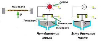
The internal mechanism of the pressure sensor consists of a metal membrane and a rheostat. When the thin plate deflects under the influence of the oil pumped by the pump, the working part of the variable resistor will move and the resistance value at the output of the device will change significantly.
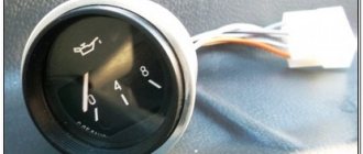
Changing the parameters of the electric current directed to the dial indicator will be reflected in the displacement of the instrument needle. The presence of divisions on the dial allows you to approximately determine the pressure in the oil line of the sensor.
In parallel with the rheostat, a relay is installed in the sensor housing, which is also connected to the device membrane. If there is a complete absence of oil or critically low pressure, the contacts will close. Turning on the electrical circuit will cause the warning light located on the instrument panel to turn on. This indicator can only light when the engine is not running or in the first few seconds after starting. In other cases, in this operating mode, the engine must be turned off and the reason for the lack of sufficient lubricant pressure must be sought.
How to check
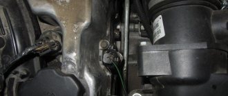
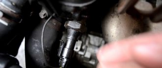
If the emergency light comes on or the instrument needle does not deviate to the right even at significant engine speeds, you must first check the control device for functionality. This element is located on the left side of the vehicle, near the fourth spark plug. The device is a small metal barrel with a wire connected to it.
The best way to check the oil sensor is to install a known-good device. For this purpose it is not necessary to use an expensive original device. You can use a simple product, which is a relay that is activated when the pressure in the oil line is low. To perform diagnostics, it is recommended to select a device whose fitting has a suitable thread. Otherwise, you can use an adapter.
To check, you can use a low-power light bulb, to which the “minus” is connected through a sensor, and the “plus” is supplied from the positive terminal of the battery. The light comes on immediately when connected, but must go out after starting the engine, otherwise it will be necessary to carry out urgent repairs to the internal combustion engine.
If there is no spare sensor, you can use a pressure gauge, with which you can more accurately set the pressure value in the oil line.
If the engine is working properly and the pump pumps liquid lubricant at the required pressure, then the reason for the lack of readings on the measuring device is not necessarily the sensor. A break in the connected wire may be one of the possible causes of a wiring malfunction, in which the arrow will not deviate and the emergency oil pressure light will light up.
What is an oil pressure sensor used for?
In an internal combustion engine, there must be a layer of lubricant between the rubbing metal parts. Otherwise, excessive heating and jamming of various rotating elements will occur. Simply adding grease, as is done in steering rod joints or wheel bearings, will not work, because the crank mechanism operates under conditions of increased mechanical loads. The best option is to use liquid oils, which are delivered to the rubbing parts using a centrifugal pump. The effectiveness of such a system can only be ensured if the lubricant is pumped under significant pressure.
It is for the continuous determination of parameters of this type that a special sensor is needed. The product, intended for installation on a VAZ 2106 car, is configured in such a way that the driver of the car can notice in time dangerous deviations in the operating mode of the internal combustion engine.
VAZ 2110 diagram
Colored wiring diagrams for the VAZ 2110 (injector and carburetor engine) are provided with a description of all elements for various modifications. The information is intended for self-repair of the car. Electrical circuits are divided into several blocks for ease of viewing via a computer or smartphone; there are also circuits in the form of a single picture with a description of the elements - for printing on a printer in one sheet.
There are two types of electrical wiring for the VAZ-2110: carburetor and injector. There are slight differences, but the basic principles of operation and wiring are the same. Depending on the location, the wiring differs into: under the hood and in the cabin. All electrical equipment of the car is connected using wires of a certain color. Each element has its own wiring harness through the blocks and fuses.
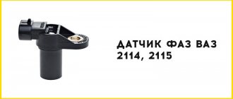
Replacing level and emergency oil pressure sensors on a VAZ 2114
From the very first to the most modern cars, lubricants are used. Without it, it is impossible to operate the machine, inside of which there is a huge number of rubbing parts. The model of the domestic manufacturer VAZ 2114 is no exception, because lubricating oil is necessarily present here. The lubrication system must always be under the control of the driver in real time. To do this, the car design provides for the use of an oil level sensor.
With its help, the driver can quickly find out that the oil level has dropped to an unacceptably low level, and therefore appropriate action should be taken.
Appearance of the DUM
Design and principle of operation
The internal mechanism of the pressure sensor consists of a metal membrane and a rheostat. When the thin plate deflects under the influence of the oil pumped by the pump, the working part of the variable resistor will move and the resistance value at the output of the device will change significantly.
Changing the parameters of the electric current directed to the dial indicator will be reflected in the displacement of the instrument needle. The presence of divisions on the dial allows you to approximately determine the pressure in the oil line of the sensor.
In parallel with the rheostat, a relay is installed in the sensor housing, which is also connected to the device membrane. If there is a complete absence of oil or critically low pressure, the contacts will close. Turning on the electrical circuit will cause the warning light located on the instrument panel to turn on. This indicator can only light when the engine is not running or in the first few seconds after starting. In other cases, in this operating mode, the engine must be turned off and the reason for the lack of sufficient lubricant pressure must be sought.
Schemes of individual six units
Generator connection diagram
1 — battery VAZ-2106; 2 — “six” generator set; 3 - regulatory device designed to control the operating voltage parameter; 4 - lock; 5 — plastic module with safety elements; 6 - control light indicator that determines the battery charge; 7 - relay that protects the power line of the battery charge indicator light.
1 — car starter device; 2 - battery; 3 - generator set; 4 - ignition switch.
1 — spark plugs; 2 - distributor; 3 — ignition switch; 4 - coil; 5 - switch; 6 - generator; 7 - battery.
Carburetor valve control circuit
1 - limit switching device of the carburetor unit; 2 - the engine valve itself; 3 - module used to control the carburetor unit; 4 — ignition coil; 5 - switching device; 6 - ignition switch, is a lock.
Wiring diagram of direction indicators and signaling
1 — lighting devices for turning lights installed in the front optical devices; 2 — battery VAZ-2106; 3 - car generator unit; 4 — side turning lights located on the front fenders; 5 — main mounting module with safety elements; 6 - auxiliary control unit with safety devices; 7 — ignition switch; 8 - device for turning off and activating the light signal, mounted in the car interior on the center console; 9 - switching device for activating and disabling turning lights; 10 - interrupting device used for blinking turning lights and light signals; 11 — speedometer, equipped with a control light indicator for activation of turning lights; 12 — light devices for direction indicators in the rear optics.
Electrical circuit for turning on the sound
1 - sound devices used to reproduce impulses; 2 - relay for activation of sound impulses, protects the electrical circuit from overvoltage; 3 — switch of sound pulses; 4 — mounting module with safety elements; 5 — generator set VAZ 2106; 6 - battery.
Switching diagram for electric windows
1 - main safety module; 2 - relay used to protect the power line of additionally installed power windows; 3 — switching device for the electric window mounted on the left door; 4 - a similar device used to adjust the position of the glass in the front right door; 5 — electric motor of the left glass lift; 6 — auxiliary module with safety elements; 7 - ignition switch.
Engine cooling system diagram
1 — generator unit, installed under the hood; 2 - battery; 3 - ignition switch or lock; 4 — main module with safety elements; 5 - relay that protects the power line of the activation system of the electric motor of the power unit cooling fan; 6 — ventilation device activation controller; 7 - the fan itself; 8 - auxiliary safety module.
What is an oil pressure sensor used for?
In an internal combustion engine, there must be a layer of lubricant between the rubbing metal parts. Otherwise, excessive heating and jamming of various rotating elements will occur. Simply adding grease, as is done in steering rod joints or wheel bearings, will not work, because the crank mechanism operates under conditions of increased mechanical loads. The best option is to use liquid oils, which are delivered to the rubbing parts using a centrifugal pump. The effectiveness of such a system can only be ensured if the lubricant is pumped under significant pressure.
It is for the continuous determination of parameters of this type that a special sensor is needed. The product, intended for installation on a VAZ 2106 car, is configured in such a way that the driver of the car can notice in time dangerous deviations in the operating mode of the internal combustion engine.
Methods for checking temperature sensors
If the driver wants to make sure that the cause of problems with the car is the antifreeze sensor, then he will have to carry out a simple checking procedure. But before you start, you need to make sure the integrity of the car wiring. As mentioned above, for the sensor to work normally, it must be continuously supplied with a voltage of 5 volts. To make sure that the supplied voltage does not deviate from this value, you should start the car, and then remove the wires from the sensor and connect them to a multimeter. If the device clearly shows 5 volts, then there are no problems with the wiring and you can begin to examine the sensor itself. There are two verification methods. Let's list them.
Hot water test
The sequence of actions in this option is simple.
- The sensor is placed in a pan of cold water. An electronic thermometer is also placed there (it is much more convenient than a regular one, because the measured temperatures will be quite high).
| Temperature, °C | Resistance, Ohm |
| +5 | 7280 |
| +10 | 5670 |
| +15 | 4450 |
| +20 | 3520 |
| +25 | 2796 |
| +30 | 2238 |
| +40 | 1459 |
| +45 | 1188 |
| +50 | 973 |
| +60 | 667 |
| +70 | 467 |
| +80 | 332 |
| +90 | 241 |
| +100 | 177 |
This method of checking the sensor is simpler than the previous one, but less accurate. It is based on the fact that the temperature of boiling water reaches one hundred degrees and does not rise higher. Therefore, this temperature can be used as a reference point and find out what the sensor resistance will be at one hundred degrees. The sensor is connected to a multimeter switched to resistance measurement mode, and then immersed in boiling water. However, you should not expect the multimeter to show a resistance of 177 ohms, which corresponds to a temperature of one hundred degrees. The fact is that the temperature of water constantly decreases during the boiling process and averages 94–96 °C. Therefore, the resistance on the multimeter will vary from 195 to 210 ohms. And if the numbers produced by the multimeter differ from the above by more than 10%, the sensor is faulty and it’s time to change it.
What to do when the oil pressure light comes on on Zhiguli cars
Service center specialists advise drivers of any cars, both domestic and imported, to stop driving and turn off the engine at the first signal of a drop in engine oil. When the oil pressure sensor is triggered, it is clear that there is some problem with the engine.
First action
The first thing to do after stopping is to measure the oil level. It is likely that it is below the minimum mark and you just need to add the required amount of liquid. After adding, it is necessary to take another measurement - if the level is between the Max and Min marks, then we can conclude that the sensor was triggered precisely because of a lack of oil in the engine. Try to start the engine, if the oil can icon disappears, then the problem is solved.
In VAZ-2106, VAZ-2107, VAZ-2109 cars special oil pressure sensors were installed. Modern models have not used this type of device for a long time. The oil pressure sensor on all cars of the Zhiguli family performs the same function - it measures the amount of lubricant in the engine unit. If there is not enough oil, the friction force between the moving parts of the engine increases, and this leads to rapid breakdown of both the valves, the camshaft or crankshaft, and cylinders.
The oil pressure sensor on classic VAZ models is mounted directly on the engine itself. And in the cabin, on the left side of the steering wheel, there is a dial-type indicator that shows the driver the current state of oil pressure. However, the oil can itself lights up only in one case - when there is completely no pressure in the system. The sensor cannot show any intermediate positions: either the pressure in the system is normal or there is no pressure at all.
What's next
Therefore, if you have checked the oil level and it is normal, you will need to take other measures. Maybe you recently changed the engine oil to new one? In this case, the likely cause of a sharp drop in oil pressure while driving is a defective filter. Alas, this is not uncommon these days. You will have to carry out the procedure of changing the oil and oil filter again.
Checking the sensor
Do not exclude the possibility that the oil pressure sensor is to blame. It is likely that the engine is not in any danger at all, but the sensor wiring is shorted or its life has expired, which is why it is sending incorrect signals.
To make sure that the fault lies in the sensor, you need to start the engine and at idle speed press the gas pedal to 1000–1100 rpm. If the oil can icon immediately disappears, it means that the oil pressure in the engine is actually normal and your car does not require repair. But the sensor will need to be replaced, since for various reasons it does not work.
Oil quality control
In cases where the oil filter and pressure sensor are in working condition, and the light continues to light, it is necessary to once again check the oil level in the engine, or rather, carefully inspect the oil dipstick itself. In some cases, antifreeze or gasoline may enter the engine, causing the oil level to rise. It is enough to lower the dipstick into the water; if bright stains characteristic of oil remain on the surface, it means that gasoline or coolant has actually entered the engine.
An interesting article about biofuel produced from ordinary sawdust, read more here.
In this case, a minimum of engine flushing will be required, but most likely a major overhaul - service station specialists will determine the reason why foreign liquids are entering the unit.
The final stage
It is also likely that during the operation of the vehicle, the wires from the sensor to the light bulb were damaged or the oil paths became clogged. If you do not have the skills to work with electronics, it is best to turn to professionals at a service station.
Location and appearance of the device
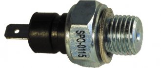
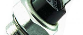
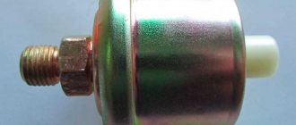
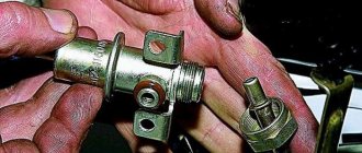
The sensor installed on classic VAZ 2106 models consists of the following parts:
- an element in the form of a round metal barrel with one terminal for connecting a wire (factory name - MM393A);
- the second part is a membrane switch in the form of a nut with a contact at the end (designation MM120);
- a steel tee into which the above parts are screwed;
- sealing bronze washers.
The large “barrel” MM393A is designed to measure pressure, the “nut” with the MM120 terminal fixes its absence, and the tee is a connecting element that is screwed into the engine. The location of the sensor is on the left wall of the cylinder block (if you look in the direction of movement of the car) under spark plug No. 4. Do not confuse the device with the temperature sensor installed higher in the cylinder head. Wires leading inside the cabin, to the dashboard, are connected to both contacts.
In later models of the “classic” VAZ 2107, the indicator arrow on the dashboard is missing, only a warning lamp is left. Therefore, a stripped-down version of the sensor is used without a tee and a large barrel.
Oil pump drive
The oil pump drive is a part that needs to be discussed separately. The fact is that the duration of operation of the entire motor depends on it. The drive part of the oil pump itself consists of several parts:
- parasitic shaft;
- intermediate gear;
- small shaft;
- big shaft
The drive is considered a simple pump part, but the gear splines wear out quickly during operation
Most cases of oil pump failure are associated with drive failure, or more precisely, with wear of the gear splines. Most often, the splines “lick off” when starting the car in winter; in this case, the engine cannot be started again.
Gear wear is an irreversible process during long-term operation of the machine. If the gear teeth begin to slip, the pressure in the oil system will be below operating pressure. Accordingly, the engine will not receive the amount of lubricant that it needs for normal operation.
How to replace the pump drive
Replacing the drive gear is not an easy procedure, but after careful preparation, you can remove the drive and repair it:
- Remove the car's ignition distributor.
- To remove the intermediate gear, you will need a special puller. However, you can get by with a simple wooden stick with a diameter of about 9–10 mm. The stick needs to be hammered into the gear and then rotated clockwise. The gear will then easily come out.
- Install a new one in place of the worn gear using a regular stick.
- Replace the ignition distributor.
Video: replacing the oil pump drive mechanism
What is a “hog” and where is it located?
The VAZ 2106 mechanisms include a shaft, which is called the “hog” (or “pig”). The shaft itself drives the car's oil pump, as well as the gasoline pump and sensors. Therefore, if the “hog” suddenly fails, then the machine ceases to function normally.
The intermediate shaft is located in the engine compartment of the VAZ 2106 on the front side of the cylinder block. On the “six” the “hog” is started using a chain drive. This shaft has an extremely simple structure - only two necks. However, if the bushings on the journals are heavily worn, the operation of the oil pump and other mechanisms will be difficult. Therefore, when checking the pump, they usually look at the operation of the “hog”.
The shaft, called the “hog”, is mounted in front of the cylinder head
You can work with the oil pump on the VAZ 2106 yourself in the garage. The main feature of domestic “sixes” is precisely their unpretentious maintenance and simplicity of design. You can repair the oil pump and adjust the pressure in the system yourself, since there are no special requirements for this procedure.
Concept and purpose ↑
The oil pressure indicator is designed to read the atmospheric pressure in the pipeline and display the indicators on a mechanical sensor. New models are equipped with a digital device, with many related functions. Directly in the VAZ, the device is located at the rear of the engine on the left side.
Replacement algorithm:
- It is enough to get a flat platform with free access on the sides. We don’t need an inspection hole or a roadside overpass;
- We will prepare a set of automotive tools, rags, and a new sensor. You can purchase the device at any auto store or car market. The cost is cheap, even by modern standards;
- turn off the vehicle, release the handbrake;
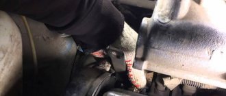
- open the hood, use the fatal 19 key to unscrew the sensor itself, disconnect the terminal blocks of the electrical wires from it;
- We install new equipment in place of old, non-working equipment. We carry out the assembly procedure in reverse order;
- We start the engine, look at the readings, and check that the markings match. If the wrong sensor is installed, inaccurate readings may occur. The driver may receive data that does not correspond to reality.
Elements, lubrication systems, its structure and principle of operation
The main elements of the lubrication system are:
- Carter with pan;
- Pump;
- Filter;
- Radiator;
- Bypass valves;
- Highway and canals;
- Sensors
The design of the lubrication system for different types and types of engines is different and can differ significantly from each other in the presence or absence of certain components or systems.
The sump is the lowest part of the engine.
Its main task is to store and cool the lubricant. In addition, its design includes special baffles that calm the disturbance of the oil when the car moves over uneven surfaces. The sump is secured to the crankcase with bolts; between them there is a sealing gasket that prevents oil leakage from the power plant. To determine the required amount of oil, a dipstick is used, on the surface of which special marks are applied.
The pump serves to pump oil from the crankcase and create oil pressure in the internal combustion engine channels.
It is possible to install pumps of various types, depending on the design of the power plant. The most popular are gear and rotary pumps. A gear pump can have internal or external gears. The oil supply in a gear pump is carried out at a constant pressure, while in a rotary pump the pressure can be varied. The oil pressure in the engine channel, depending on its design, can be from 2-16 atmospheres.
The filter cleans the oil from mechanical impurities and carbon deposits.
Thanks to this, the service life of the power unit and oil is increased. In addition, by absorbing debris, it simplifies maintenance of the lubrication system. When changing the oil, the filter must also be replaced.
The radiator cools the engine oil.
The use of a radiator is determined by the intended purpose of the engine. Not all engines require the use of such a device. Mostly, high-revving and heavily loaded engines are equipped with radiators.
Radiators come in two types, air or liquid cooled. The principle of air, blowing with a stream of air while the car is moving. That is why such devices are located in the front of the unit, providing it with a sufficient amount of air. Liquid radiators are cooled by the engine cooling system.
Bypass and pressure reducing valves ensure normal pressure in the lubrication system.
The valve's task is to relieve excess pressure when it increases above the established norm. To protect devices and engine components, several valves are installed in the design. For example, in an oil pump, filter, etc. When the filter is clogged, in order not to stall the operation of the engine and the system as a whole, the bypass valve allows oil to bypass it.
The line and channels are holes for oil circulation.
They are located inside many engine parts and make up the oil supply system to the rubbing elements. The main line leads from the pump to the filter and has a larger cross-section; it also supplies lubricant to the crankshaft bearings.
Sensors measure and transmit indicators necessary for the normal operation of the system.
The main indicators are: pressure, temperature, oil level. The most important readings are taken by the oil pressure sensor. If there is a sudden drop in pressure, the system as a whole may fail, so the sensor readings are displayed on the dashboard.
The pressure sensor is installed in the central line. In more modern engines, it transmits readings to a computer, or electronic control unit. If the required indicators are exceeded, the electronics completely stops the system.
Fuel level
On the “sixes” a fuel level indicator of the BM-150 type is installed, the controller itself is mounted in the gas tank according to the scheme, and it is fixed with bolts. The FLS includes a resistor device and a float. In order for the controller to indicate the correct level of gasoline in the system, a resistor device is controlled by the movement of the float.
The fuel level indicator float itself is directly connected to the resistor using a lever, at the end of which there is a sliding element. Thanks to the latter, the gasoline reserve lamp on the dashboard can light up. If the controller adjustment is correct, then this light comes on when there are 5-6 liters of gasoline in the tank.
The controller diagnostic procedure is carried out by measuring the resistance level of the resistor device. If the gas tank is empty, this parameter should be about 315-345 Ohms, if it is half full - 108-128 Ohms, if full - about 70 Ohms. Diagnostics is carried out using a combined tester (the author of the video is VAZ 2101-2107 REPAIR AND MAINTENANCE).
As for the temperature indicator, the VAZ 2106 uses a TM-106 type device; this regulator is also often called a fan switch sensor. The controller itself is made in the form of a screw, which is connected to the cylinder block. As for the operating principle of the temperature sensor or fan sensor, it is similar to that described above. But only in this case is a thermistor element installed, which changes the resistance parameter depending on the temperature of the consumable material.
The correct operation of the engine depends on the fan switch on sensor, because if the temperature is too high and the fan does not start working, this will lead to overheating of the motor. There is an engine temperature indicator on the car dashboard, allowing the car owner to always know about its condition.
JOT and the fan switch on sensor on a carburetor machine are two different sensors, and on an injection machine there is one sensor.
Six DTOZH
All about the oil pressure sensor in cars 2106
To ensure that the car does not fail at the most unexpected moment, the owner must monitor the serviceability of all systems. Regularly diagnose and troubleshoot problems. One of these system elements is the state of the oil pressure sensor. If its indicators are too high or low, there is a possibility of breakdowns, the elimination of which will require large material costs.
The oil pressure sensor of the VAZ 2106 was produced quite successfully, since it is equipped with an indicator with an arrow and a special signal lamp, and does not require special skills to understand its components.
Design and operating features
Currently, sensors in VAZ cars are:
- electrical,
- mechanical.
The option with electrical devices is more modern, but not as reliable, since it does not provide the owner with sufficient information about the condition of the oil level.
The mechanics are simpler, but at the same time, more accurate. They are the ones who are installed in the “sixes”.
Such devices are quite reliable. The basis of their work is the transfer of information from the membrane, the position of which changes under the influence of deviations in the amount of liquid from the original mark. The size of the changes is recorded by a variable resistor, which are transmitted to the pressure gauge, and the level is shown by an arrow. The DDM is located behind the engine, on the left.
In order for the signal to be transmitted from the motor to the dashboard, the following basic elements are used:
- oil pressure gauge,
- variable and temperature compensation resistor,
- signal light bulb
- a magnet, with the help of which the needle is kept at the zero mark,
- fuse.
The entire system operates when the engine is running. When a device malfunctions, it is best to simply replace it with a new one. Its cost is low, and if it is disassembled, it may malfunction again.
How to check the sensor for serviceability
If the oil pressure decreases, then the arrow drops to the zero mark, the light comes on, and this indicates a malfunction
The car owner should pay attention to this and fix the problem.
If such a situation arises, first of all, it is necessary to inspect the engine compartment for oil leaks. If they are missing, check the fluid level in the engine. If there is too little oil, this may well cause a drop in pressure.
If there is a sufficient amount of fluid, it is necessary to check the pressure sensor by performing appropriate diagnostics. To do this, you will need a device such as a pressure gauge and a key.
Using a key, you need to remove the sensor and connect a pressure gauge in its place. Next, start the car and observe how the instrument needle behaves. With a gradual increase in speed, the needle should change relative to the crankshaft speed, but not exceeding the seven atmospheres indicator.
After all the measurements have been taken, if the indicators are normal, then everything is in order with the pressure, the cause of the malfunction is in the device. After this, it is replaced.
There is also another option for checking the DDM. It is usually used when trouble occurs while driving. To do this, you will need to remove the device from the socket and crank the starter without starting the engine. If the problem lies in the sensor, then oil will come out of the socket. This means that you will also need to install a new, working device.
How to connect a new sensor
To replace the device with a new one, you do not need any special skills; the process is quite simple. First, you will need to prepare the necessary tools. The sequence and connection diagram will be as follows:
- disconnect all wires from the sensor,
- use the key to get it out,
- repair or replace the device and, after connecting all the wires, return it to its place.
After this, you need to make sure that the new unit is working properly.
VAZ cars have a fairly simple, but at the same time effective system for monitoring oil metering parameters. And if a malfunction occurs, it will not be difficult to replace it with your own hands.
Replacement and repair
It is easy to determine where the oil pressure sensor is located from the descriptions given above. There are other meters located in this sector, so care should be taken when performing work to replace or repair the sensor (it is possible to mistakenly remove the coolant temperature sensor).
This type of control element is inexpensive, so it is irrational to waste time trying to fix the problem yourself. Moreover, after self-repair, the correctness of the performance of such a device will remain a big question. If there is a suspicion that the oil pressure sensor is faulty, it should be replaced.
The work is carried out in the following sequence:
- Turn off the ignition.
- Remove the contact wire from the terminal.
- Using a wrench, unscrew the sensor.
- Install the new sensor in the reverse order of removal.
In this case, care should be taken not to overtighten the threads, the failure of which will require much more expensive repairs.
Types, design features of oil pump
1. drive gear 2. pump housing 3. suction channel 4. driven gear 5. axle 6. discharge channel 7. separating sector 8. driven rotor 9. driving rotor
The most important element in this system is the oil pump. This unit ensures that oil is pumped into the channels, which then flows to the components and mechanisms. Since some of the motor components are force-lubricated, the lubricant must be supplied under pressure. In addition, a number of elements that require lubrication by splashing are located quite high relative to the pump itself (for example, a camshaft installed in the cylinder head), and oil still needs to be supplied to it through channels, which is impossible without creating pressure that ensures the movement of the lubricant to high-lying elements.
There are several types of oil pumps used on cars:
- Gear;
- Rotary;
Moreover, each type includes several types that differ in design. Thus, gear pumps come with external and internal gearing.
Video: Engine lubrication system
External Gear Pump
1. driven gear 2. suction channel 3. drive gear 4. drive shaft 5. discharge channel 6. driven gear axis
An external gear pump consists of two gears mounted in a housing. They interact with each other due to the engagement of teeth located on the outside. One of the gears is the drive gear and can be driven by the crankshaft or camshaft. The second gear is driven and rotates due to meshing.
The housing has two channels - supply and discharge. The feeder is connected to an oil intake, the other end of which is lowered into a pan with oil. The outlet channel is connected to lines that supply lubricant to the rubbing surfaces.
Such a pump operates on a simple principle: oil from the supply channel enters the gear meshing zone, is captured by the teeth and is pumped into the discharge channel. This ensures pressure in the system.
Internal gear pump
The internal gear pump has a slightly different design. There are also two gears placed in the pump housing, but one is located inside the second. The inner gear is the drive gear and its teeth are located on the outside. The driven gear is external and its gear sector is made from the inside. Moreover, the axes of these gears do not coincide, therefore, on one side, a crescent-shaped cavity is formed between them, in which a crescent-shaped separating sector is placed. Moreover, the beginning of this cavity is located near the supply channel, and the end is located near the outlet channel.
This pump works like this: when rotating, oil from the supply channel, thanks to the gap formed at the beginning of the formation of a cavity between the gears, gets between the teeth of the driven element. As it receives rotation from the drive gear, the oil moves towards the outlet channel inside the cavity, and the separating sector cuts off excess lubricant and prevents it from flowing between the teeth.
Behind the separating sector, the volume of the cavity decreases as it ends and the zone where the gears begin to engage appears. In this zone, the oil is compressed by the teeth, but at this moment the oil passes the location of the outlet channel into which it is already released under pressure.
Something else useful for you:
- Why does the engine consume oil?
- What is engine compression and how to measure it?
- Why does the engine get hot: reasons for overheating and what it can lead to
Location and appearance of the device
The sensor installed on classic VAZ 2106 models consists of the following parts:
- an element in the form of a round metal barrel with one terminal for connecting a wire (factory name - MM393A);
- the second part is a membrane switch in the form of a nut with a contact at the end (designation MM120);
- a steel tee into which the above parts are screwed;
- sealing bronze washers.
The large “barrel” MM393A is designed to measure pressure, the “nut” with the MM120 terminal fixes its absence, and the tee is a connecting element that is screwed into the engine. The location of the sensor is on the left wall of the cylinder block (if you look in the direction of movement of the car) under spark plug No. 4. Do not confuse the device with the temperature sensor installed higher in the cylinder head. Wires leading inside the cabin, to the dashboard, are connected to both contacts.
In later models of the “classic” VAZ 2107, the indicator arrow on the dashboard is missing, only a warning lamp is left. Therefore, a stripped-down version of the sensor is used without a tee and a large barrel.
Complication of design
Using the example of a 2.5 liter diesel engine from VW, you can see how much more complex the operation of the lubrication system of a modern engine has become. Let's look at the purpose of each of the elements.
- Two-stage internal gear type oil pump. Installed in the oil pan.
- Oil pressure regulating valve. Using a solenoid valve, the ECU (Engine Control Module) directs oil to different channels, thereby switching the operating modes of the oil pump. When regulating performance, the engine load, coolant temperature, crankshaft speed and signals from the automatic transmission are taken into account. When a control signal is applied, the valve opens, allowing oil to flow into the channels of the first stage (the pressure in the system is about 1.8 atmospheres). In the absence of a control “mass”, the return spring returns the valve to its original position, changes the direction of oil flow, raising the pressure in the system to 3.3-4 Atm.
Changing the performance makes it possible to reduce the mechanical losses spent on lubrication and cooling of the engine’s rubbing pairs. This solution increases the overall efficiency of engines, reducing the amount of harmful emissions.
- Check valves in return lines. They allow lubricant to flow in only one direction and prevent complete drainage of oil from the channels after the engine is stopped. Filled channels allow you to avoid oil starvation in the first seconds after starting the engine.
- Safety valve. Opens during a cold start when excessive pressure develops in the system.
- Small circuit valve. Triggers when the filter element is clogged, opening the way for oil to bypass the filter.
- Oil cooler. Oil and coolant circulate through the heat exchanger housing.
- The cooler helps maintain the thermal balance of the engine and prevents oil overheating.
- Oil injector valve. It opens when the design pressure is reached in the system, opening the line to the injectors.
- Oil nozzle. Sprays oil onto the piston crown, removing heat from it.
- Pressure reducing valve. Triggers when excessive pressure is reached in the system, protecting the cylinder head from excess oil.