The crank mechanism (abbreviated as KShM) ensures the conversion of the translational-rotational movement of the piston inside the cylinder into the rotational movement of the engine crankshaft. For a standard four-cylinder engine, the crankshaft includes a cylinder block with a crankcase, a cylinder head, an engine sump, pistons complete with piston rings and pins, connecting rods (on which the pistons are mounted), a crankshaft and a flywheel.
The main part of the crankshaft (and the engine in general) is the cylinder block. It consists not only of cylinders (Fig. 2.7) and piston group parts, but also of a number of other elements: channels, plugs, bearings, drillings. The crankshaft, which is mounted on special bearings, rotates precisely in the cylinder block.
The crankcase is located at the bottom of the cylinder block. Coolant constantly circulates inside the cylinder block while the engine is running: in the summer it can be simple water, but in the cold season it is necessary to use antifreeze or antifreeze. Also inside the cylinder block are oil channels that belong to the engine lubrication system.
Piston pin
The piston pin serves to articulate the piston with the connecting rod. It is a tube passing through the upper head of the connecting rod and installed at its ends into the piston bosses. The piston pin is secured to the bosses by two retaining spring rings located in special grooves of the bosses. This fastening allows the finger (in this case it is called a floating finger) to rotate. Its entire surface becomes working, and it wears out less. The pin axis in the piston bosses can be shifted relative to the cylinder axis by 1.5...2.0 mm in the direction of the greater lateral force. This reduces piston knock in a cold engine.
Piston pins are made of high quality steel. To ensure high wear resistance, their outer cylindrical surface is hardened or carburized, and then ground and polished.
The piston group consists of a fairly large number of parts (piston, rings, pin), the mass of which can fluctuate for technological reasons; within certain limits. If the difference in the mass of the piston groups in different cylinders is significant, then additional inertial loads will arise during engine operation. Therefore, piston groups for one engine are selected so that they differ insignificantly in weight (for heavy engines by no more than 10 g).
connecting rod
The connecting rod connects the piston to the crank of the crankshaft and, transforming the reciprocating motion of the piston group into the rotational movement of the crankshaft, makes a complex movement, while being subjected to alternating shock loads. The connecting rod consists of three structural elements: rod 2, upper (piston) head 1 and lower (crank) head 3. The connecting rod rod usually has an I-section. To reduce friction, a bronze bushing 6 with a hole for supplying oil to the rubbing surfaces is pressed into the upper head to reduce friction. The lower head of the connecting rod is split to allow assembly with the crankshaft. For gasoline engines, the head connector is usually located at an angle of 90° to the axis of the connecting rod. In diesel engines, the lower head of the connecting rod 7, as a rule, has an oblique connector. The lower head cover 4 is attached to the connecting rod with two connecting rod bolts, precisely matched to the holes in the connecting rod and the cover to ensure high precision assembly. To prevent the fastening from loosening, the bolt nuts are secured with cotter pins, lock washers or lock nuts. The hole in the lower head is bored together with the cover, so the connecting rod covers cannot be interchangeable.
Rice. Parts of the connecting rod group: 1 - upper head of the connecting rod; 2 - rod; 3 — lower head of the connecting rod; 4 — lower head cover; 5 — liners; 6 — bushing; 7 — diesel connecting rod; S - main connecting rod of the articulated connecting rod unit
To reduce friction in the connection of the connecting rod with the crankshaft and facilitate engine repair, a connecting rod bearing is installed in the lower head of the connecting rod, which is made in the form of two thin-walled steel liners 5 filled with an antifriction alloy. The inner surface of the liners is precisely adjusted to the crankshaft journals. To fix the liners relative to the head, they have bent antennae that fit into the corresponding grooves in the head. The supply of oil to the rubbing surfaces is provided by annular grooves and holes in the liners.
To ensure good balance of the parts of the crank mechanism, the connecting rod groups of one engine (as well as the piston ones) must have the same mass with its corresponding distribution between the upper and lower heads of the connecting rod.
V-twin engines sometimes use articulated connecting rod assemblies, consisting of paired connecting rods. The main connecting rod 8, which has a conventional design, is connected to the piston of one row. An auxiliary trailing connecting rod, connected by the upper head to a piston of another row, is pivotally attached with a pin to the lower head of the main connecting rod by the lower head.
Operating principle of the crank mechanism
The operating principle of the crank mechanism has not changed over the past three centuries.
During the power stroke, the working mixture ignited at the end of the compression stroke quickly burns, the combustion products expand and push the piston down. He pushes the connecting rod, which rests on the lower axis, spaced apart from the main longitudinal axis. As a result, under the influence of tangentially applied forces, the crankshaft rotates a quarter of a turn in four-stroke engines and half a turn in two-stroke engines. Thus, the longitudinal movement of the piston is converted into rotation of the shaft.
Read also: Lenten borscht with lemon juice
Calculation of the crank mechanism requires excellent knowledge of applied mechanics, kinematics, and strength of materials. It is entrusted to the most experienced engineers.
Application area
Today, the ratchet as a part is used in the creation of various industrial units with components of engineering structures. At the same time, stable operation of various small elements of tools can be ensured. This point indicates the versatility of using ratchet mechanisms.
From a technical integration point of view, the device outperforms many other designs.
Very often, manufacturers use a ratchet as an element through which operating parameters are set. An example is fixing the cutting step in a certain range. In addition, installation is carried out during the direct manufacture of machine tools.
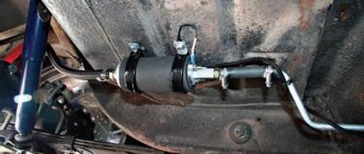
Recently, installation has been carried out in cylindrical grinding machines, the device provides radial feed. The mechanism is found in jacks and various winch systems, wind-up cars and other devices.
List of KShM malfunctions
The most common mechanism failures are:
- wear and destruction of the crankshaft connecting rod and main journals;
- grinding, chipping or melting of plain bearing shells;
- contamination of piston rings by combustion carbon deposits;
- overheating and breakage of rings;
- accumulation of carbon deposits on the piston head leads to its overheating and possible destruction;
- Long-term operation of the engine with detonation effects causes the piston crown to burn out.
The combination of these faults with a malfunction in the lubrication system can cause misalignment of the pistons in the cylinders and engine seizure. Elimination of all these breakdowns involves dismantling the engine and its partial or complete disassembly.
Repairs take a long time and are expensive, so it is better to identify malfunctions in the early stages and correct problems in a timely manner.
Crankshaft
Let's move on to the crankshaft. It has a rather complex shape. Its axis is the main journals, through which it is connected to the cylinder block. To ensure a rigid connection, but again movable, the shaft seats in the block are made in the form of half rings, the second part of these half rings are the covers with which the shaft is pressed to the block. The covers are connected to the block with bolts.
4 cylinder engine crankshaft
Flywheel
The flywheel is attached to the crankshaft shank flange. It is a carefully balanced cast iron disk of a certain mass. In addition to ensuring uniform rotation of the crankshaft, the flywheel helps overcome compression resistance in the cylinders when starting the engine and short-term overloads, for example, when starting a vehicle. A ring gear is attached to the flywheel rim to start the engine from the starter. The surface of the flywheel that comes into contact with the clutch driven disc is ground and polished.
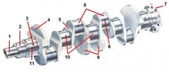
Rice. Crankshaft: 1 - toe; 2 — connecting rod journal; 3 - molar neck; 4 - cheek; 5 - counterweight; 6 - shank with flange
Operating principle of KShM
The operation of the engine mechanism is based on the expansion energy during combustion of the fuel-air mixture. It is these “micro-explosions” that are the driving force that the crank mechanism transforms into a convenient form. The video below describes in detail the principle of operation of the KShM in 3D animation.
Operating principle of the KShM:
- Fuel atomized and mixed with air burns in the engine cylinders. This dispersion does not involve slow combustion, but instantaneous combustion, due to which the air in the cylinder expands sharply.
- The piston, which is at the top point at the moment the fuel begins to burn, drops sharply down. This is the linear movement of the piston in the cylinder.
- The connecting rod is connected to the piston and crankshaft so that it can move (deviate) in the same plane. The piston pushes the connecting rod, which is placed on the crankshaft journal. Thanks to the movable connection, the impulse from the piston through the connecting rod is transmitted tangentially to the crankshaft, that is, the shaft rotates.
- Since all the pistons take turns pushing the crankshaft using the same principle, their reciprocating motion translates into rotation of the crankshaft.
- The flywheel adds rotational momentum when the piston is at its “dead” points.
Interestingly, to start the engine you must first spin the flywheel. For this purpose, you need a starter that engages with the flywheel ring gear and spins it until the engine starts. The law of conservation of energy in action.
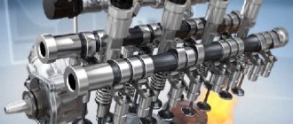
The remaining engine elements: valves, camshafts, pushers, cooling system, lubrication system, timing belt and others are necessary parts and components to ensure the operation of the crankshaft.
Cylinder block
A cylinder head is installed on the carefully processed upper plane of the cylinder block, which closes the cylinders from above. In the head above the cylinders there are recesses that form combustion chambers. For liquid-cooled engines, a cooling jacket is provided in the body of the cylinder head, which communicates with the cooling jacket of the cylinder block. With the valves located at the top, the head has seats for them, inlet and outlet channels, threaded holes for installing spark plugs (for gasoline engines) or injectors (for diesel engines), lubrication system lines, mounting and other auxiliary holes. The material for the block head is usually aluminum alloy or cast iron.
A tight connection between the cylinder block and the cylinder head is ensured using bolts or studs with nuts. To seal the joint in order to prevent leakage of gases from the cylinders and coolant from the cooling jacket, a gasket is installed between the cylinder block and the cylinder head. It is usually made of asbestos cardboard and lined with thin steel or copper sheet. Sometimes the gasket is rubbed with graphite on both sides to protect it from sticking.
The lower part of the crankcase, which protects the parts of the crank and other engine mechanisms from contamination, is usually called the sump. In relatively low-power engines, the pan also serves as a reservoir for engine oil. The pallet is most often cast or made from steel sheet by stamping. To eliminate oil leakage, a gasket is installed between the crankcase and the sump (on low-power engines, a sealant called “liquid gasket” is often used to seal this joint).
Engine frame
The fixed parts of the crank mechanism connected to each other are the core of the engine, which absorbs all the main power and thermal loads, both internal (related to the operation of the engine) and external (due to the transmission and chassis). The force loads transmitted to the engine frame from the vehicle's supporting system (frame, body, housing) and back significantly depend on the method of engine mounting. Usually it is attached at three or four points so that loads caused by distortions of the supporting system that occur when the machine moves over uneven surfaces are not taken into account. The engine mounting must exclude the possibility of its displacement in the horizontal plane under the influence of longitudinal and transverse forces (during acceleration, braking, turning, etc.). To reduce vibration transmitted to the supporting system of the vehicle from a running engine, rubber cushions of various designs are installed between the engine and the sub-engine frame at the mounting points.
The piston group of the crank mechanism is formed by a piston assembly with a set of compression and oil rings, a piston pin and its fastening parts. Its purpose is to perceive gas pressure during the power stroke and transmit force to the crankshaft through the connecting rod, carry out other auxiliary strokes, and also seal the above-piston cavity of the cylinder to prevent gases from breaking through into the crankcase and the penetration of engine oil into it.
Note.
A considerable proportion of attached motor equipment is mounted on the cylinder block, and when the engine is turned on, it works with it as a single unit.
As for the purpose and principle of operation of the piston and other parts of the piston group, we have already discussed this above. Let us only recall that under the force of powerful pressure that is formed in the cylinder after combustion of the working mixture, the piston moves down and transmits its movement through the connecting rod (on which it is installed) to the crankshaft, forming the very torque with which the car is driven into movement.
Know that the internal combustion engine operates in a rather harsh regime. At idle speed (that is, when the engine is running, but the car is stationary in neutral), the crankshaft rotates at a speed of 600-900 revolutions per minute (or about 10-16 revolutions per second). When driving at medium speed, the engine works even more intensely, and the crankshaft rotates at a speed of 2000 to 3000 rpm. And in modern sports cars, the crankshaft rotation speed can exceed 200 revolutions per second (10,000 - 13,000 revolutions per minute).
Consequently, the pistons in the cylinders move up and down very quickly. We have already noted earlier that in one full revolution of the crankshaft, the piston manages to cover the distance between TDC and BDC twice. So: he performs these movements literally in a fraction of a second. If we add to this powerful pressure, as well as high temperature in each cylinder, then the operating conditions of the internal combustion engine can be called extreme.
Sleeve
Removable sleeve
There are two types of sleeves - made directly in the block and being part of them, and removable. As for those made in the block, they are cylindrical recesses in it of the required height and diameter.
Removable ones also have a cylindrical shape, but they are open at the ends. Often, in order to securely fit into its seat in the block, there is a small ebb in the upper part that ensures this. In the lower part, for density, rubber rings are used, installed in the flow grooves on the sleeve.
The inner surface of the liner is called the mirror because it is highly machined to ensure the lowest possible friction between the piston and the mirror.
In two-stroke engines, several holes are made in the liner at a certain level, which are called windows. In the classic internal combustion engine design, three windows are used - for inlet, outlet and bypass of the fuel mixture and waste products. In opposed installations such as OROS, which are also push-pull, there is no need for a bypass window.
Piston with rings and pin
The piston is a small cylindrical part made of aluminum alloy. Its main purpose is to convert the pressure of released gases into translational motion transmitted to the connecting rod. The reciprocating movement is ensured by the sleeve.
The piston consists of a skirt, a head and a bottom (bottom). The bottom can have different shapes (convex, concave or flat), and it contains the combustion chamber. On the head there are small grooves for piston rings (oil scraper and compression).
Compression-type rings prevent possible gases from entering the engine crankcase, and low-removal type rings are designed to remove excess oil from the cylinder walls.
The skirt is equipped with special bosses with holes for installing the piston pin connecting the piston and connecting rod.
connecting rod
The connecting rod is another part of the crankshaft, which is made of steel by stamping or forging, equipped with hinged joints. The connecting rod is designed to transfer motion energy from the piston to the shaft.
The connecting rod consists of an upper, collapsible lower head and a rod. The upper head is connected to the piston pin. The lower collapsible head can be connected to the shaft journal using caps (connecting rod).
Crank (knee)
A piston connecting rod is attached to any crank (elbow). Often the crank is located from the axis of the journals within a certain radius, which determines the stroke of the piston. It was this detail that gave the name to the crank mechanism.
Crankshaft
Another moving part of a mechanism of complex configuration, made of cast iron or steel. The main purpose of the shaft is to convert the translational piston movement of the piston into rotational torque.
The crankshaft consists of journals (main, connecting rod), cheeks (connecting the journals) and counterweights. The cheeks create balance during the operation of the entire mechanism. Inside the neck and cheeks are equipped with small holes through which oil is supplied under pressure.
Flywheel
The flywheel is usually mounted at the end of the shaft. Made from cast iron. The flywheel is designed to increase uniform rotation of the shaft to start the engine using a starter.
Currently, dual-mass type flywheels are more often used - two disks that are quite tightly connected to each other.
Cylinder block
This is a stationary part of the crankshaft, which is made of cast iron or aluminum. The block is designed to guide the pistons; it is in them that the entire work process is carried out.
The cylinder block can be equipped with cooling jackets, bearing beds (camshaft and crankshaft), and mounting point.
Cylinder head
This part is equipped with a combustion chamber, passages (intake and exhaust), spark plug holes, bushings and seats. The cylinder head is made of aluminum.
Like the block, the head also has a cooling jacket that connects to the cylinder jacket. But the tightness of this connection is ensured by a special gasket.
The head is closed with a small stamped lid, and a rubber gasket that is resistant to oil is installed between them.
The piston, cylinder liner and connecting rod form what motorists commonly call a cylinder. An engine can have from one to 16, and sometimes more, cylinders. The more cylinders, the larger the total displacement of the engine and, accordingly, the greater its power. But you need to understand that simultaneously with power, fuel consumption also increases. The cylinders in the engine can be arranged in different layouts:
- in-line (the axes of all cylinders are located in the same plane)
- V-shaped layout (cylinder axes are located at an angle of 60 or 120 degrees in two planes)
- opposed layout (cylinder axes are located at an angle of 180 degrees)
- VR layout (similar to V-shaped, but the planes are located at a slight angle relative to each other)
- The W-shaped arrangement is a combination of two VR-arrangements on one crankshaft, located in a V-shape with an offset relative to the vertical
The balancing of the engine, as well as its size, depends on the layout. The boxer engine has the best balance, but it is rarely used on cars due to its design features.
The in-line six-cylinder engine also has excellent balance, but its use in modern cars is almost impossible due to its bulkiness. V-shaped and W-shaped engines are most widespread due to the best combination of dynamic characteristics and design features.
Cylinder
Cylinders are the guiding elements ⭐ of the crank mechanism. Pistons move inside them. The length of the cylinder generatrix is determined by the stroke of the piston and its dimensions. Cylinders operate under conditions of sharply changing pressure in the above-piston cavity. Their walls come into contact with flames and hot gases with temperatures up to 1500... 2500 °C.
Cylinders must be strong, rigid, heat and wear resistant with limited lubrication. In addition, the cylinder material must have good casting properties and be easy to machine. Typically, cylinders are made from special alloy cast iron, but aluminum alloys and steel can also be used. The inner working surface of the cylinder, called its mirror, is carefully processed and plated with chrome to reduce friction, increase wear resistance and durability.
In liquid-cooled engines, the cylinders may be cast together with the cylinder block or as separate liners installed in the block bores. Between the outer walls of the cylinders and the block there are cavities called a cooling jacket. The latter is filled with liquid that cools the engine. If the cylinder liner is in direct contact with the coolant with its outer surface, then it is called wet. Otherwise it is called dry. The use of replaceable wet liners makes engine repair easier. When installed in a block, wet liners are reliably sealed.
Air-cooled engine cylinders are cast individually. To improve heat dissipation, their outer surfaces are equipped with annular fins. On most air-cooled engines, the cylinders and their heads are secured with common bolts or studs to the top of the crankcase.
In a V-shaped engine, the cylinders of one row may be slightly offset relative to the cylinders of the other row. This is due to the fact that two connecting rods are attached to each crank of the crankshaft, one of which is intended for the piston of the right half of the block, and the other for the piston of the left half of the block.