Crankshafts are: composite, forged, cast, solid and made of steel and cast iron. For example, cast iron crankshafts have been used in automobile engines since 1960. High-strength cast irons according to GOST 7293-85 are divided into two classes: pearlitic (VCh 45-0; VCh 50-1.5; VCh60-2) and ferritic (VCh40-0 VCh40-6). The crankshaft is made by hot stamping from alloy steel (engines of cars ZIL-130, MAZ-5335, KamAZ-5320, etc.) or cast from high-strength cast iron (engines of cars of the GAZ family, VAZ, etc.) with or without counterweights. The crankshaft of the YaMZ-236, YaMZ-238 engines is made of 50G steel. During the manufacturing process, the shaft is subjected to heat treatment and tempering to a hardness of 229-269 HB, and the surfaces of the connecting rod and main journals and the journal for oil seals are hardened with heating with high frequency currents to increase wear resistance. (The depth of the hardened layer for the main and connecting rod journals is 3.0 -4.0 mm, and on the journals for the oil seal 1.0-2.0 mm; and hardness after hardening 52-62 HRC).The crankshafts of KamAZ-740 engines are made by hot stamping from steel 42 KHMFA-Sh. High-tin steel-aluminum liners are widely used in crankshafts due to the fact that they have increased fatigue resistance, good extreme pressure properties and corrosion resistance, which increases engine reliability. [1].
What is a crankshaft
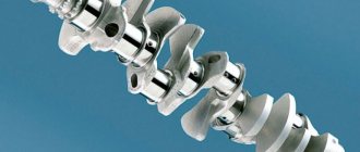
The crankshaft is a mechanical part of a car engine, which is an intermediate link that converts the thermal energy of burned fuel into the mechanical energy of wheel rotation. In appearance, it is a shaft made of a steel alloy with many connecting rod journals, which are connected to each other by a knee journal. The number of necks and elbows corresponds to the number of cylinders in the engine, their location, and shape. The journals are connected to the pistons through connecting rods, which, moving back and forth, set the shaft in motion.
If the crankshaft has connecting rod journals on both sides of the crankshaft, it is called full support. If they are located only on one side - incomplete support.
The crankshaft is made from high-wear carbon or alloy steel (for sports cars, luxury models and high-performance vehicles) or modified cast iron (for standard production models) by casting or extrusion. Molybdenum, chromium and other metals are used to alloy steel, significantly increasing the strength of the alloy.
In most engines, the crankshaft is located in the lower part, above the crankcase; in opposed engines, it is located higher, in the center of the engine.
This is interesting: Adjusting the carburetor yourself
What is the crankshaft made of?
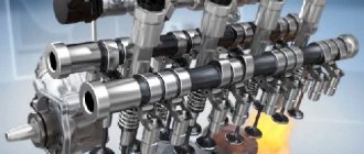
Crankshaft design: 1. Crankshaft nose; 2. The seat of the camshaft drive sprocket (gear); 3. Oil supply hole to the main journal; 4. Counterweight; 5. Cheek; 6. Crankpins; 7. Flywheel flange; 8. Oil supply hole to the connecting rod journal; 9. Counterweights; 10. Root necks; 11. Main journal of the thrust bearing.
Working components of the crankshaft:
- The main journal is a shaft support that serves as the axis of rotation of the shaft itself. It lies in a bearing that is built into the crankcase.
- Crankpins are supports connected to the piston connecting rods. During operation, they shift relative to the shaft axis along a circular path.
- Cheeks are auxiliary parts connecting the connecting rod and main journals. They also prevent shaft destruction due to resonant loading.
- Shank - The rear part connected to the take-off gear or flywheel to transfer power to movement.
- The toe is the front part of the shaft, which, through a pulley or gear, transmits power to the drive of the gas distribution unit and other auxiliary mechanisms.
- Counterweights are parts necessary to distribute the load and balance the mass of connecting rods and pistons.
Protective seals are used to seal the nose and shank. This prevents oil from leaking where the flywheel parts extend beyond the cylinder block. The rotational movement is provided by thin steel plain bearings. To prevent the axis of rotation of the shaft from shifting, a thrust bearing is placed on one of the main journals.
During work, the greatest stresses are concentrated at the junction of the necks and cheeks. To unload it, it is made with a fillet - a semicircular transition with an intermediate technological belt. Due to extreme loads at the junction of the cheeks and journals, at one time manufacturers abandoned composite crankshafts, the parts of which were connected by fasteners.
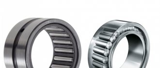
Difference between main and connecting rod bearings
You need to know that there are two types of liners. These are connecting rods and main ones. The first are located between the connecting rod and the crankshaft journal. The root element is similar to the first in its purpose. However, it is located where the crankshaft passes through the engine housing. The inserts vary in size. Dimensions depend on the type of internal combustion engine for which a specific part is manufactured. There are also special repair inserts. They are different from the original new ones installed in the engine. Repair inserts differ only in marks that are multiples of 0.25 mm. So, their sizes are approximately the following - 0.25 mm, 0.5 mm, 0.75 mm, 1 mm.
Why are crankshafts called flat?
In the process of studying the structure of the crankshaft, sometimes it seems that you are in a biology lesson. The first thing that catches your eye is the massive flat “cheeks”, between which there are “necks”. Some journals (as you probably know) are main journals (the shaft rests on them while lying in the crankcase) and connecting rods (it is to them that the connecting rods “cling” from above). If you look at the crankshaft from the front, two options are possible: either the cheeks and journals lie in the same plane, or half of them are located at right angles to the other half. In the first case, the shaft is called flat.
When assembling the engine of your small car, a flat shaft was probably used - this is a natural solution for a 4-cylinder engine. But when creating a V-shaped “eight”, you already have a choice. Initially (at the dawn of the automotive industry), all designers preferred flat shafts, but with increasing power, power units generated more and more vibrations and became increasingly difficult to balance. It was in an attempt to reduce the level of vibration that the creators of the motors came up with a scheme with the necks installed at right angles to each other. And now most V-shaped eights have just such crankshafts. And “flat” ones remained the lot of racing engines or engines for supercars - you can recall Ferrari power units or the 5-liter engine under the hood of the new Shelby Mustang GT350.
The easiest way to understand the difference between a flat-plane crankshaft (right) and a crankshaft with journals mounted at right angles is to use pictures.
Motorists are not going to completely abandon the flat crankshaft. After all, a simpler design makes it more compact and lighter, which means that, other things being equal, such a shaft is able to spin faster, making the engine more responsive. In addition, over the last hundred years, metallurgists have not been lazy - and thanks to advanced materials, which make it possible to make a part noticeably lighter at the same dimensions, modern flat shafts have an order of magnitude less vibration than their distant ancestors.
The question remains: why then are the crankshafts of 4-cylinder engines made flat? The fact is that the level of vibrations caused by the so-called. forces of inertia of the 2nd order (it is they that appear on V-shaped “eights” with a flat crankshaft), strongly depends on the displacement of the engine. 4-cylinder engines are compact - so sometimes you can simply turn a blind eye to such vibrations. And if it’s not possible, it’s easier and cheaper to use the so-called. balance shafts. Which we will talk about another time.
Dimensions
The thickness of the main bearing is about 1.5-2 millimeters. It should be noted that sometimes a different composition may be used as materials for the production of this part - instead of copper and lead-tin alloys, special aluminum-based alloys are used.
But there is no standardization of materials for the manufacture of these products - each manufacturer makes the liner according to its own unique formulas. The only thing that unites the products with each other is the steel strip.
Practice shows that the following layer sizes are used in the production of plain bearings. Thus, the thickness of the steel base is 0.9 millimeters or more. The main layer has a thickness of up to 0.75 millimeters. Nickel layer – 0.001. The layer of tin and lead alloy is 0.02-0.04 millimeters. Tin layer - 0.005.
Any alloys used in production are individually selected for each engine and calculated taking into account the hardness of the materials from which the crankshaft is made. To increase the service life and performance of new or repair motors, it is recommended to use only those parts that the manufacturer recommends.
The thinner the main bearing, the better performance it has. Thinner products lie on the bed much better, have better heat dissipation, and the gaps in them are smaller. In modern motors, manufacturers are trying to use thinner plain bearings.
The liner must be made from more than just the right components. The shape is also very important. The fact is that for proper installation it is necessary that the bearing have an interference fit on the diameter of the crankshaft bed.
The tension is made not only along the diameter of the product, but also along its length. This makes it possible to achieve excellent contact between the bearing liner and the bed. For shafts with a diameter of up to 40 millimeters, the interference should be from 0.03 to 0.05 millimeters. For larger shafts (70 millimeters) and above, the interference ranges from 0.06 to 0.08 millimeters.
This part also has an upper part - these are the main bearing caps. They are fixed with bolts or studs on the engine crankcase.
This part, namely the liner, is produced by stamping from a steel strip. The stamp gives the part its shape. And then the end parts and working surface are processed. This detail is very accurate. Tolerance from the nominal size to 0.02 millimeters in length and up to 0.005 in thickness.
What is the crankshaft sensor for?
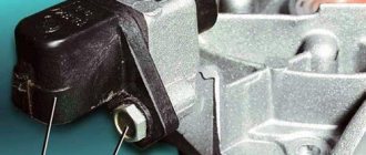
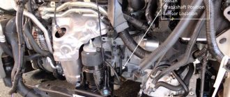
The crankshaft position sensor (CPS) is used in vehicles equipped with electronic engine control systems. Since shaft rotation affects the operation of many functional units and systems, timely supply of fuel to the internal combustion engine cylinders can improve driving characteristics. The crankshaft sensor is responsible for synchronizing work processes. In various car models, its use improves the timing of the ignition or fuel injectors. The device transmits data on the crankshaft position, direction and speed to the electronic control unit.
The following types of sensors are available:
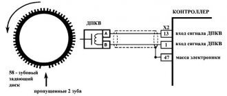
- Magnetic (inductive type) . The signal to the ECU is generated when the synchronization mark passes through the magnetic field that is formed around the sensor. The system does not require separate power and can operate in parallel as a speed sensor.
- Hall sensors (work on the Hall effect) . The current in the device begins to move when a changing magnetic field approaches. The magnetic field overlap is realized by a special synchronizing disk, the teeth of which interact with the magnetic field of the DPKV. An additional function is the ignition distribution sensor.
- Optical . In this case, a toothed disk is also used for synchronization. It blocks the optical flow passing between the receiver and the LED. The receiver detects interruptions in the light flux and transmits a voltage pulse corresponding to the shaft rotation parameters to the electronic control unit.
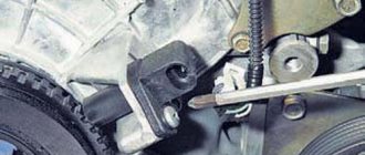
The crankshaft sensor is installed inside the engine housing, like other control sensors. To install it, a special bracket is used, located near the generator drive pulley. Externally, it differs from sensors for other purposes in the presence of a 55-70 cm long wire with a special connector that connects the device to the electronic control system.
How a crankshaft works - a look from the inside
The operating principle of the crankshaft is as follows. At the moment of maximum removal of the piston, the cheeks and the crankshaft connecting rod are pulled into one line. At this time, fuel begins to burn in the cylinders, and, accordingly, flammable gases are released, which move the piston towards the crankshaft. The connecting rod also moves with it, the lower head of which rotates the crankshaft relative to its axis. As soon as it turns 180°, the crankpin begins to move in the opposite direction, thus moving the piston.
The following picture emerges: the piston evenly moves away and then approaches the part; the extreme points of the piston are called “dead”, since in these positions its speed is zero. Thus, we figured out how the crankshaft works.
The lubrication system in the part also plays an important role . An oil supply is provided from the common line to the main journal supports, which is supplied under pressure. Next, through special channels located in the cheeks, this oil is supplied to the connecting rod journals. Thanks to the oil film, the wear resistance of these elements increases. In addition, oil pressure can be used to check whether the crankshaft journals need replacing. Having decided what the crankshaft is needed for, we can safely say that it occupies one of the leading positions among engine parts.
Home →
Device →
Engine →
Crankshaft (crankshaft) →
This is interesting: Refilling car air conditioners - instructions for a comfortable climate!
KShM device
The engine crank mechanism consists of three main parts:
- Cylinder-piston group (CPG).
- Connecting rod.
- Crankshaft.
All these components are located in the cylinder block.
The purpose of the CPG is to convert the energy released during combustion into mechanical action - forward motion. The CPG consists of a liner - a stationary part placed in a block in the cylinder block, and a piston that moves inside this liner.
After the air-fuel mixture is supplied inside the liner, it ignites (from an external source in gasoline engines and due to high pressure in diesel engines). Ignition is accompanied by a strong increase in pressure inside the liner. And since the piston is a moving element, the resulting pressure leads to its movement (in fact, gases push it out of the liner). It turns out that the energy released during combustion is converted into the translational movement of the piston.
For normal combustion of the mixture, certain conditions must be created - the maximum possible tightness of the space in front of the piston, called the combustion chamber (where combustion occurs), an ignition source (in gasoline engines), the supply of a combustible mixture and the removal of combustion products.
The tightness of the space is ensured by the block head, which covers one end of the liner, and by piston rings mounted on the piston. These rings also belong to the CPG parts.
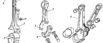
connecting rod
The next component of the crankshaft is the connecting rod. It is designed to connect the CPG piston and the crankshaft and transmit mechanical action between them.
The connecting rod is an I-shaped cross-section rod, which provides the part with high bending resistance. At the ends of the rod there are heads, thanks to which the connecting rod is connected to the piston and crankshaft.
In fact, the connecting rod heads are eyes through which shafts pass, providing a hinged (movable) connection of all parts. At the junction of the connecting rod with the piston, a piston pin (referred to as a CPG) acts as a shaft, which passes through the piston bosses and the connecting rod head. Since the piston pin is removed, the upper head of the connecting rod is one-piece.
At the junction of the connecting rod with the crankshaft, the connecting rod journals of the latter act as a shaft. The lower head has a split design, which allows the connecting rod to be secured to the crankshaft (the removable part is called the cap).
Crankshaft
The purpose of the crankshaft is to provide the second stage of energy conversion. The crankshaft converts the forward motion of the piston into its own rotation. This element of the crank mechanism has a complex geometry.
The crankshaft consists of journals - short cylindrical shafts connected into a single structure. The crankshaft uses two types of journals - main and connecting rod. The first ones are located on the same axis, they are supporting and are designed to movably secure the crankshaft in the cylinder block.
The crankshaft is fixed in the cylinder block with special covers. To reduce friction at the junction of the main journals with the cylinder block and connecting rods with the connecting rod, friction bearings are used.
The connecting rod journals are located at a certain lateral distance from the main ones and the connecting rod is attached to them with the lower head.
The main and connecting rod journals are connected to each other by cheeks. In diesel crankshafts, counterweights are additionally attached to the cheeks, designed to reduce the oscillatory movements of the shaft.
The connecting rod journals together with the cheeks form a so-called U-shaped crank, which converts translational motion into rotation of the crankshaft. Due to the remote location of the connecting rod journals, when the shaft rotates, they move in a circle, and the main journals rotate about their axis.
The number of connecting rod journals corresponds to the number of engine cylinders, while the main ones are always one more, which provides each crank with two support points.
At one end of the crankshaft there is a flange for attaching the flywheel - a massive disk-shaped element. Its main purpose: the accumulation of kinetic energy due to which the reverse operation of the mechanism is carried out - the transformation of rotation into the movement of the piston. At the second end of the shaft there are seats for drive gears of other systems and mechanisms, as well as a hole for fixing the drive pulley of motor attachments.
Crankshaft elements
The crankshaft (crankshaft) of an internal combustion engine consists of:
- Root neck.
- Crankpin.
- Cheeks.
- The front output part of the shaft or, in other words, the toe.
- The rear output part of the shaft, or, in other words, the shank.
- Counterweights.
The crankshaft journal is a special seat for the main bearing on which the crankshaft sits and rotates.
Designations for the figure “Internal combustion engine crankshaft”:
- Flywheel flange.
- Counterweights.
- Crankpins.
- Root necks.
- Cheek.
- Oil supply holes to the journals.
- Counterweights.
- Main thrust bearing journal.
- The seat of the camshaft drive sprocket (gear).
- Crankshaft nose.
In the structure of the internal combustion engine crankshaft there are main journals connected to the connecting rod journals through the cheeks. In addition to the connecting function of the cheeks, they are also balancers of the crank mechanism, that is, they equalize the weight of the pistons and connecting rods. Thanks to the balanced rotation of the crankshaft, the engine runs smoothly without jerking.
Sliding bearings, called liners, are placed on the main and connecting rod journals. Thin-walled, half-walled liners made of steel tape with an anti-friction layer (that is, resistant to friction).
The connecting rod journal is the support for the connecting rod. The transition points from the journals to the cheeks are subject to the greatest load in the structure of the internal combustion engine crankshaft.
To ensure that the entire engine crankshaft does not move along the axis and does not have axial play, a thrust plain bearing is used. A sliding bearing that prevents movement along the crankshaft axis is installed on the outer or middle main journals.
In the design of the crankshaft journals and cheeks, the designers provide special holes for lubrication. Through these holes, engine oil is supplied under pressure to each shaft journal. The main journals are provided with such individual lubrication. Through channels in the cheeks, oil is supplied to the connecting rod journals.
The rear part of the crankshaft is the shank that transmits torque to the flywheel, which is mounted on the shank, and the flywheel, in turn, transmits rotation to the gearbox.
The front of the crankshaft is the sock. The following parts are mounted on the toe:
- gear or sprocket driving the camshaft (camshaft) of the gas distribution mechanism (timing mechanism);
- attachment drive pulley. By the way, we looked at how to remove the crankshaft pulley in detail. There are several ways.
A so-called torque vibration damper is also mounted on the toe. Since the internal combustion engine crankshaft is constantly experiencing enormous torsional and fracture loads, it is necessary to suppress vibration (oscillations) at the toe.
The crankshaft vibration damper consists of two discs and a tensile element (rubber, silicone, oil fluid, spring). Vibration at the shaft toe is reduced thanks to a torsional vibration damper.
Requirements
We already know what this node is for. Since it is the main crank mechanism, special requirements are placed on it. The shaft must withstand enormous loads during engine operation. Therefore, it is made from high-strength alloys and cast iron with the addition of molybdenum and chromium.
High demands are placed not only on the composition, but also on the manufacturing technology of the mechanism. On conventional internal combustion engines, the crankshaft is made by cast iron. But for souped-up, sports cars , the shaft must be forged. Such mechanisms are made from special alloys. This crankshaft has a lighter weight, which allows increasing the power of the internal combustion engine and its efficiency. Why are such shafts not made everywhere? The answer lies in the cost of production. The technology used to make forged shafts is complex and expensive. This will significantly increase the final cost of the internal combustion engine and the car itself.
Service Process
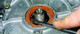
Like any part, the crankshaft requires special care. For inspection and repair, it must be removed. This is usually required during a major overhaul, for example, after a water hammer, during which the crankshaft may move.
To remove the crankshaft, it is necessary to dismantle the engine and its elements. Having turned the internal combustion engine over, mark the location of the main bearing caps, then remove them, lift the crankshaft and disconnect the rear sealing ring. After this, remove the liners from the cylinder blocks and covers. Thus, we have a disconnected crankshaft.
To check it, you need to wash the part with gasoline and dry it. An inspection is carried out for cracks, chips, and dents. If any are found, the part must be replaced.
By unscrewing the plugs, you can clean all the oil channels. The connecting rod harnesses are ground and polished, and the oil passages are cleaned again. Bearing shells, nose bearing, flywheel, oil seal and rubber seals must also be replaced if defects are detected.
After this, the engine is assembled in the reverse order of disassembly, having previously lubricated all parts. You also need to make sure that the part slides and rotates smoothly.
Causes of failure
Structural damage and wear during operation are the most common reasons for replacing parts. Despite the regular supply of lubricant and careful operation of the motor, this process is inevitable. Over time, the surface of the journals becomes thinner, the free space between them becomes larger, because of this the crankshaft acquires free movement, the oil pressure decreases and, as a result, its supply decreases. All this causes premature failure of the entire engine system.
Scrolling is the second reason for repair work. Many people have heard about this or dealt with this problem on their own, but not all car owners know why this situation arises. Connecting rod bearings have thin plates that fit into a special bed. In this case, small protrusions are placed along the entire outer surface of the half rings; they should come into contact with the front part of the block, as is the case in new motors. Some conditions reduce the resistance of the antennae in relation to the liner; it sticks to the crankshaft journal and rotates. In such a situation, engine operation stops. It is worth noting the most common reasons for its development:
- the operation of the motor is associated with constant exceeding of the established loads;
- the lubricant has too liquid a structure;
- bearing caps are installed with low interference;
- lack of oil, its excessive viscosity or the presence of abrasive compounds in the composition.