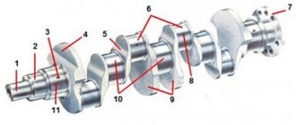
How to check the phase sensor
Checking the functionality of the internal combustion engine phase sensor is carried out using a diagnostic tool, as well as using an electronic multimeter capable of operating in DC voltage measurement mode. We will discuss an example of a test for phase sensors of a VAZ-2114 car. On models with a 16-valve engine, a sensor model 21120-3706040 is installed, and on 8-valve engines - 21110-3706040.
First of all, before diagnostics, the sensors must be removed from their mounting location. After this, you need to visually inspect the DF housing, as well as its contacts and terminal block. If there is dirt and/or debris on the contacts, it must be removed with alcohol or gasoline.
To check the sensor of the 8-valve engine 21110-3706040, it must be connected to a battery and an electronic multimeter according to the diagram shown in the figure.
Next, the verification algorithm will be as follows:
- Set the supply voltage to +13.5±0.5 Volts (you can use a regular car battery for power supply).
- In this case, the voltage between the signal wire and ground must be at least 90% of the supply (that is, 0.9V). If it is lower, and even more so equal or close to zero, then the sensor is faulty.
- Bring a steel plate to the end of the sensor (with which it is directed towards the camshaft reference).
- If the sensor is working properly, then the voltage between the signal wire and ground should be no more than 0.4 Volts. If more, it means the sensor is faulty.
- Remove the steel plate from the end of the sensor, the voltage on the signal wire should again return to the original 90% of the supply voltage.
To check the phase sensor of a 16-valve engine 21120-3706040, it must be connected to a power supply and a multimeter according to the diagram shown in the second figure.
To test the corresponding phase sensor, you will need a metal piece with a width of at least 20 mm, a length of at least 80 mm and a thickness of 0.5 mm. The verification algorithm will be similar, however, with other voltage values:
- Set the supply voltage on the sensor to +13.5±0.5 Volts.
- In this case, if the sensor is working properly, then the voltage between the signal wire and ground should not exceed 0.4 Volts.
- Place a pre-prepared steel piece into the sensor slot where the camshaft reference is placed.
- If the sensor is working properly, then the voltage on the signal wire should be at least 90% of the supply voltage.
- Remove the plate from the sensor, and the voltage should again drop to a value of no more than 0.4 Volts.
In principle, such checks can be performed without removing the sensor from its mounting location. However, to inspect it, it is better to remove it. Often, when checking a sensor, it makes sense to check the integrity of the wires, as well as the quality of the contacts. For example, there are cases when the chip does not hold the contact tightly, which is why the sensor does not receive a signal to the electronic control unit. Also, if possible, it is advisable to “ring” the wires going from the sensor to the ECU and to the relay (power wire).
In addition to checking with a multimeter, you need to check for relevant sensor errors using a diagnostic tool. If such errors are detected for the first time, you can try to reset them using software, or simply by disconnecting the negative terminal of the battery for a few seconds. If the error appears again, additional diagnostics are needed using the above algorithms.
Typical phase sensor errors:
- P0340 - no camshaft position sensor signal;
- P0341 - valve timing does not coincide with the compression/intake strokes of the cylinder-piston group;
- P0342 - the signal level in the electrical circuit of the DPRV is too low (detected when there is a short to ground);
- P0343 - the signal level from the meter exceeds the norm (usually occurs when the wiring is broken);
- P0339 - an intermittent signal is received from the sensor.
Thus, if these errors are detected, it is advisable to perform additional diagnostics as quickly as possible so that the engine operates in optimal operating mode.
Source
Replacing chips and pinout of crankshaft sensor VAZ 2110
Over time, the wires leading to the remote control connector became frayed. Located under the engine and near the front wheels, chemically aggressive environments in the form of dirt, snow, oil and salt get onto the remote control and its microcircuit, which leads to slow oxidation of the wires on the microcircuit and subsequently to their breakdown. Since the connector wires are bundled, a repair fitting with two 15 cm long protruding wires is supplied with the replacement. After removing the damaged connector, install the new connector on the "twisted" connection. Insulate the bend with heat shrink adhesive or pipe tape.
As can be seen from the diagram below, their pinout is not anything complicated. Two wires are connected directly to the signal input contacts of the control unit, passing along the entire length of the harness. It is necessary to observe the polarity of connecting the signal wires of the sensor to the control unit. If the polarity is reversed, the synchronization system will not work. To restore the operation of the DPKV, simply replace the wires and check for correct operation by starting the engine.
Replacing DPKV VAZ 2112 with your own hands
Having accurately determined the breakdown of this part, you can begin to replace the sensor yourself. To perform this operation you will need the following tools and materials:
- Set of wrenches and socket heads.
- New DPKV.
- Slotted screwdriver.
- Rags.
It is recommended to carry out work on replacing the DPKV in the following sequence:
- Place the car on a flat surface.
- Secure the machine with wheel chocks and apply the parking brake.
- Disconnect the negative terminal of the battery.
- Using a screwdriver, pry up the block with wires and disconnect it from the DPKV.
- Using a 10mm socket wrench, unscrew the bolt holding the sensor.
- Remove the DPKV.
After troubleshooting the seat, a new part is installed in the reverse order of removal. After completion of installation work, the functionality of the DPKV should be checked.
For this purpose, you need to start the engine, warm it up and drive the car for several kilometers under different loads on the internal combustion engine. If no abnormalities are found, then replacing the crankshaft sensor can be considered successful.
Functionality check
Don't rush to conclusions. Don't blame the crankshaft sensor for all problems. Sometimes it turns out that the cause of the malfunction is not at all the same. Therefore, you first need to check whether the crankshaft sensor is working properly.
There are several ways to check this.
- With a multimeter. Your task is to measure the resistance of the coil on the inductive sensor. If it's good, the reading will be between 500 and 700 ohms.
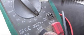
Multimeter
- Set your multimeter to 200 millivolts, attach a stylus to the cable, and drag a metal object near the core several times. If the probe is working, it will be able to detect this metal and a voltage spike will appear on the display. If there is no rupture, replace the DC.
- Oscilloscope. This verification method gives the most objective and accurate result, almost 100%. Connect the device to the engine and read data in different modes. You will need to start the engine at different speeds - from 800 to 6000. Look at the lines that appear on the screen. If they are different lengths, you should look for the cause of the malfunction. Sometimes simple cleaning of dirt, checking the pulley for damage and other actions helps.
Crankshaft sensor: why does it break and how to replace it?
December 10, 2013
Probably every car enthusiast has found himself in a situation where one fine day, after turning the ignition key, his “iron friend” completely refuses to start. Oddly enough, the reason for this may be not only a dead battery or a burnt-out starter, but also a crankshaft sensor. If its body has been deformed or the entire structure has moved a couple of millimeters to the side, this part needs to be replaced. And when your garage neighbors tell you that replacing this element is a rather complicated operation that requires special, expensive tools, do not believe these words. You can change the crankshaft sensor yourself. Moreover, by doing this kind of work, you save a lot of money on service station services and at the same time gain experience in this area. Therefore, today’s article will be important for all motorists.
Why does the crankshaft sensor fail?
Based on the readings of this part, the injection system synchronizes the operation of the injectors and ignition. Therefore, injection is not possible without this part. And when the crankshaft sensor stops working, interruptions begin in the engine. Therefore, not a single modern car can do without this small spare part. And in order to prevent this malfunction, you need to regularly check the condition of the sensor. But when the symptoms began to become reality, the driver had no choice but to urgently replace it.
How to remove the crankshaft sensor?
Let us immediately note that this procedure can be performed without a special lift. So, let's get to work. First, unscrew the sensor mounting bolts that connect it to the gearbox. In fact, to remove the necessary spare part, we only need this stage. But since this part is located in a very hard-to-reach place (almost on the bottom), we will have to work hard. To work we need an extension cord, an 11 mm wrench and, of course, good lighting
It is important that the length of the first part is about 80-90 centimeters. If you have these tools, unscrew the bolts
But before you remove the crankshaft sensor, pay special attention to the rubber pad. If in the future it is poorly installed or its gap is equal to at least 1 millimeter, all readings of the measuring device will be inaccurate, and, accordingly, the engine will operate intermittently
It is best to mark this part and put it in a separate place.
The entire process of removing the spare part, bolts and lining must be carried out with great care. This part doesn't like rough handling.
Next, take a new crankshaft sensor and mount it in place of the old one. During installation, this element should be lowered through the entire engine compartment so as not to catch the connector from the installed element on top. Then don't forget about the gasket. We mount it carefully and check the integrity of the structure
It is important that the gap between it and the sensor is minimal or completely absent. After this, we attach the wires to the part, connect all the connectors and start the ignition
If you did everything correctly, rest assured that the engine will start with half a turn.
Unforgivable Movie Mistakes You Probably Never Noticed There are probably very few people who don't enjoy watching movies. However, even in the best cinema there are mistakes that the viewer can notice.
13 signs that you have the best husband Husbands are truly great people. What a pity that good spouses don't grow on trees. If your significant other does these 13 things, then you can s.
7 Body Parts You Shouldn't Touch with Your Hands Think of your body as a temple: you can use it, but there are some sacred places that you shouldn't touch with your hands. Research showing.
Contrary to all stereotypes: a girl with a rare genetic disorder conquers the fashion world. This girl's name is Melanie Gaydos, and she burst into the fashion world quickly, shocking, inspiring and destroying stupid stereotypes.
Never do this in church! If you are not sure whether you are behaving correctly in church or not, then you are probably not acting as you should. Here's a list of terrible ones.
Why do you need a tiny pocket on jeans? Everyone knows that there is a tiny pocket on jeans, but few have thought about why it might be needed. Interestingly, it was originally a place for storage.
Characteristic signs of a faulty DPKV on a Priora: how to understand that the crankshaft sensor has failed
On cars, the crankshaft sensor rarely fails, but on the Priora such an element is one of many diseases. Failure of such a device can occur for various reasons. This can be as contamination of the working surface of the product, which leads to inaccuracy in its functioning. This problem can be easily solved - you need to remove the sensor and remove all contaminants. Typical signs that there are problems with the crankshaft sensor on the Priora are the following:
- A significant decrease in engine power, which is associated with the ECU switching to emergency mode (when the mixture is prepared according to average parameters).
- When the number of revolutions increases, detonation loads arise, which negatively affect the life of the CPG.
- Floating speed at idle.
- Difficulty starting the engine. If the sensor is working properly, but it is dirty or moisture gets into the contacts, then its functioning will be incorrect. In this case, it will be possible to start the engine, but, as a rule, this will happen 3-4 times.
- Dips appear during acceleration.
The manifestation of the above symptoms should force the vehicle owner to resort to identifying the cause of the malfunction and eliminating it. Otherwise, at one point the crankshaft sensor will completely fail, and a characteristic sign of this phenomenon will be the inability to start the engine. You can determine the malfunction of the DPKV on a Priora by displaying errors P0335, P0336 and P0337 on the on-board computer. Error P0335 indicates a circuit malfunction, P0336 indicates that the device indicators are outside the permissible values, and P0337 indicates a short circuit of the DPKV to ground.
All about the crankshaft position sensor
As mentioned above, replacing the crankshaft sensor on a VAZ 2110 is not done just like that. If this small and seemingly inconspicuous-looking device is not the main part or assembly of the car, its malfunction leads to several problems. Let's look at them.
Let's get started:
The first case implies this option when dirt from or oil from under the engine cover gets on the sensor. In this case, the sensor fails, and the car starts poorly, accelerates very sluggishly and the engine speed barely reaches 3000. The car system announced this by completely turning off the emergency lights, and the BC not immediately, but after a certain time, gave a signal that an urgent replacement of the crankshaft position sensor of the VAZ 2110 is required;
- The car drives normally, but the on-board computer constantly sends signals that there is a problem with the sensor. What to do in this case? You can try moving the wires, as the cause may be hidden in bad contacts. The car constantly shakes while driving, and the contacts can oxidize over time. In addition, all wiring may be damaged.
- The car started normally, but then it stalled, and I couldn’t start it again. After a certain time, the engine starts again normally, but stalls again. And in this case, the reason may lie in the wiring. In many cases, the wire going to the sensor burns out because it comes into contact with the hot exhaust manifold.
This video will help you replace the sensor yourself correctly. In addition, it is recommended to use photo instructions and other information media during the replacement process. As it becomes clear from this article, you can do a lot of things on your car with your own hands. The main thing is the instructions that you need to follow, and the rest will follow. All that remains is to do the following if problems are discovered: buy a new sensor, the price of which is not too high, and proceed with replacement.
The crankshaft position sensor (CPS) is also called a synchronization sensor, since it synchronizes its operation with the operation of the engine.
Symptoms of a Priora DPKV malfunction
If the sensor is faulty, the sign of a breakdown is sad: you simply will not be able to start the engine with normal starter operation. Of course, there are other reasons for the engine not starting. However, if you know for sure that the fuel system is working properly and the spark plugs are in order, then first of all we check the crankshaft position sensor.
Information: DPKV does not necessarily fail immediately.
Incorrect information may be provided due to metal filings or shavings adhering to the sensitive magnetic element. In addition, there is a loss of contact in the connector due to oxidation or ingress of liquids. In this case, the engine starts, but runs unevenly and intermittently.
To check the sensor, first carry out diagnostics in any way, even using the on-board computer. DPKV malfunction shows error code 0335.
How to remove and replace the crankshaft position sensor on a Chevrolet Niva
To synchronize the position of the shaft with the electronic unit, the design of the Niva Chevrolet car is equipped with a crankshaft position sensor.
This device is located not far from the drive disk, and is located on the timing cover of the mechanism drive itself.
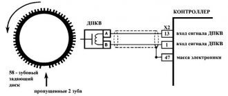
This disc is a wheel with fifty-eight teeth, and to create a certain impulse between the TDC (top dead center) and the ECU, a couple of teeth are specially removed.
Due to the fact that the crankshaft rotates, the drive disk rotates. The position of the ECU shaft is determined due to the fact that during the rotation of the disk at the sensor, magnetic fields change, thereby forming an alternating current pulse.
Sensor device
The structure of this element is the simplest, it consists of:
- Nylon frame
- This frame is wrapped in copper wires
- Has a steel core
- Insulation is provided by enamel, the base of the sealant is a compound resin
They come in different types, namely:
- The stroke sensor also distributes the ignition.
- Magnetic
- Optic
Symptoms of a problem
Sooner or later, the sensor becomes unusable, this leads to problems starting the Chevrolet Niva car, and sometimes even to the inability to stop the car while moving. The fuel supply and ignition timing depend on the position of the sensor.
- If while driving you notice a decrease in the dynamics of the car, this will indicate that this element is not corrected,
- This malfunction can also be indicated if the Check light comes on.
- In addition, a faulty sensor can be determined by the generator and timing drive.
- The revolutions go up and down and it all happens without your participation.
First of all, the position of the sensor is checked; the reason for checking may be the slightest resource cost. Also, using diagnostics, you can simply determine whether the device is fixed or not. Diagnostics means removing the product and reinstalling it; it will be in good working order if its values are approximately from 550 to 750 Ohms.
Removal, installation and inspection
Also, the first sign that it has failed is the occurrence of detonation under heavy loads on the engine itself, instability of idle speed, and a decrease in engine power. The state of the node can be understood in several ways. You just need to have the necessary equipment. If the necessary devices are available, we proceed to removing the element.
To remove it and check it, you need to do the following procedure:
- We remove the block with all the wires from it
- Unscrew the screw that secures the crankshaft sensor itself and remove it
- We check with a tester whether it is working or not
- We install the new element in place in the reverse order of removal.
By external signs you can determine the condition of the pads, the DPKV housing and whether the contacts are damaged. If no visual defects are detected, then we proceed to the inspection itself. It is carried out by means of ringing, and as mentioned above, the winding resistance should not exceed 759 Ohms, and not less than 550.
To summarize, we can conclude that this unit is the main one in the electronics, which is responsible for controlling the engine, since if it fails, then starting the engine will be impossible, so it is best to always carry it with you to insure yourself against such unpleasant consequences spare part.
If you do diagnostics and subsequent replacement, it will not take you much time and effort. The main thing is to adhere to clear rules for installation and dismantling. To extend the service life of all important elements of the Chevrolet Niva engine, timely and proper care should be carried out, not only for this device, but also for other parts.
Dismantling and installation
So, you have determined that the DPKV has failed. Therefore, there is nothing left to do but replace it. To do this you will have to dismantle the old device.
- Turn off the ignition and open the hood. Securely secure it to avoid unpleasant blows to the back or head.
- Remove any dirt from around the sensor so that it can be removed and visually inspected.
- Disconnect the wiring block from the corresponding connector.
- Using a 10 mm wrench, you can easily remove the crankshaft sensor mount.
- Remove the damaged device.
- At the same time, be sure to check the generator drive timing pulley. It is not uncommon for damage to appear on it, due to which the device cannot operate correctly. These teeth cause error codes to appear on the on-board computer.
- If there are no defects and nothing prevents the installation of a new device, begin assembly.
- If necessary, clean the installation site of the DPKV.
- Place the new measuring device in the socket and tighten the mounting bolt. In this case, do not exceed a tightening torque of more than 12 N m.
- Be sure to use the adjusting washer, which is already supplied by responsible sensor manufacturers.
- Using a special feeler gauge, make sure that there is a gap of 1 millimeter between the pulley and the DPKV core.
- The gap error can be no more than 0.41 millimeters in the upward direction. Under no circumstances should the gap be less than the required 1 mm.
Maintain clearance
Price issue
As we have already noted, VAZ 2114 owners are not often faced with the need to change the DPKV. But always be prepared for such troubles.
You don’t have to spend a lot of money purchasing a new sensor. The price depends on the store and region where car parts are sold. On average, a recreation center costs about 200-400 rubles.
Replacement at a service station is still a cost around the cost of several sensors. Therefore, think about who exactly will do the work - you or the car service specialists.
Source
AC voltage measurement
Checking the VAZ 2114 dpkv by measuring the variable component of the output signal is as follows. In order to measure the alternating component of voltage, it is necessary to ensure the appearance and absence of metal at its sensitive surface with a frequency of at least 200 Hz. To do this, you can use an auxiliary motor with a disk and a slot or protrusion, depending on the type of sensor. And power the sensor winding with a constant voltage of 1 or 2 V. Then switch the multimeter to the voltage measurement mode with a limit of up to 2 V of the alternating type. Next, you need to take a capacitor with a capacity of at least 1 μF and connect it to one of the terminals of the crankshaft position sensor, and the other end to one probe. Place the second probe on the second contact of the coil and turn on our resulting stand. Voltage should appear on the device readings when the disk rotates, this indicates that it is working properly. But, unfortunately, you will not see this voltage rating in the passport data. Because it depends on the selected capacitance, the more you increase it, the closer the readings will be to the supply voltage.
How the sensor works
On 16-valve engines, it is important to synchronize the operation of the intake and exhaust systems with the ignition operation. The electronic control unit (ECU) of the VAZ engine must receive real-time information about the position of the pistons in the cylinder liners.
Only in this case, the fuel mixture will enter the combustion chamber of the cylinder in time, and the ignition spark will fire at the right moment. Installing cylinder position sensors is irrational and expensive, since this part of the engine operates at extreme temperatures. One sensor is enough, which is located in a place convenient for maintenance and obtaining information.
Let's look at the operating principle:
- The crankshaft position sensor on the Priora is located at a fairly convenient point: outside the engine crankcase, in close proximity to the timing disk of the timing system.
- This disk (more precisely, a toothed pulley) is rigidly connected to the crankshaft and rotates with it. There is a gear calibrated wheel on it.
- Inside the device there are: a Hall element with a permanent magnet and an electrical circuit that generates an information signal for the ECU.
- Every time a wheel tooth passes the sensing element of the DPKV, an electrical impulse is generated.
- The engine control unit "knows" where each cylinder is at any given time and sets the correct intake cycle and spark timing.
It is important not only to understand the principle of operation, but also to know where the crankshaft sensor is located and how to check it.
Features of injection systems
The injection system operates thanks to a sensor system and a control unit. All signals are input to the microprocessor unit, which regulates the operation of the actuators. The following sensors are responsible for the correct operation of the engine:
- Crankshaft positions.
- Camshaft positions (not on all versions).
- Intake manifold pressure.
- Lambda probe.
- Speed.
- Mass air flow.
- Throttle position.
And the main role is played by the VAZ-2110 crankshaft sensor (8 valves or 16), since the moment of injection and supply of high voltage to the spark plug electrodes depends on it. The design has a temperature sensor, but it has virtually no effect on operation. It is necessary to control the engine temperature and send a signal to the dial indicator (or to the on-board computer). But it will be indispensable if it is necessary to implement automatic switching of fuel types (from gasoline to gas and back).
Replacement Guide
How to replace the crankshaft position sensor on a VAZ 2110? To complete the task you will only need a 10mm wrench.
Step-by-step instructions for this process are presented below:
- First you need to turn off the ignition. Just in case, to prevent possible short circuits in the vehicle's on-board network, you can disconnect the negative terminal from the battery.
- Then open the hood and find the location of the controller. You need to disconnect the connector from the regulator.
- Using a 10mm wrench, you need to unscrew the bolt that secures the device. Remove the DPKV from its installation location on the oil pump cover, and then replace it with a new regulator. Before installation, you must be sure that problems in the operation of the power unit are not caused by poor quality wiring. Otherwise, the replacement will not give the necessary results. Clean the connector and installation location of the device from dust and dirt, this will avoid possible malfunctions in its operation in the future.
Types of sensors
There are three types of DPKV, which differ in their principle of action.
- Inductive (magnetic). We have already discussed its principle of operation above. It is based on electromagnetic induction. This type of sensor is most widely used due to its efficiency and reliability. It is worth noting that for its operation and the formation of a stable signal, high speeds of the master disk and the absence of obstacles between it and the sensor (contaminants) are required.
- Hall Sensor. This type of DPKV works based on the Hall effect. When the disc teeth pass through the sensor, it produces a small signal voltage. The data is recorded and transmitted to the control unit in the form of a discrete signal. Such sensors use a reference voltage and are highly accurate, but are rarely used as DPKV.
- Optical. The operation is based on a light source and receiver (LED and photodiode). The teeth of the disk pass between them in the gap. At different rotation speeds, the teeth of the disk obscure the LED, as a result, pulse signals are formed on the photodiode, which are fed to the control unit. Due to their impracticality, such sensors are now almost never found in cars.
DPKV - what kind of sensor is it, why is it needed on Priora and why the engine does not start
From the brief introduction it is clear that the crankshaft sensor is the most important structural element on a car, without which the engine cannot operate. The main purpose of the device is to transmit a signal to the computer about the position of the crankshaft at an appropriate period of time. Reading information about the position of the crankshaft allows the control unit to decide on sending signals for fuel injection and ignition in the corresponding engine cylinders.
In addition to information about the position of the crankshaft, the sensor also informs the control unit about its rotation speed. The frequency at which the crankshaft rotates is displayed on the car's control panel, for which a tachometer is provided. The electronic method of measuring the crankshaft rotation speed is highly accurate. Based on the readings of this sensor, the following actions occur:
- The fuel injection time is set through the injectors in the corresponding cylinders.
- The ignition timing is determined, which allows fuel assemblies to be burned more efficiently and effectively.
- The efficiency of the internal combustion engine operation is assessed.
- Information about the crankshaft rotation speed is transmitted to the instrument panel, which is necessary for the driver.
By means of DPKV, the moment of passage of the pistons at the top and bottom dead centers is determined. Based on this information, engine operation is adjusted. Without such a device, not a single ECU works, so if it malfunctions, you will need to immediately resort to finding out the causes of the failure and eliminating them.
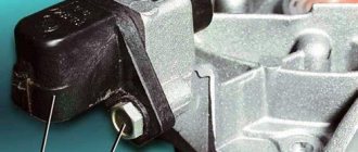
The device and where the crankshaft position sensor is located
The sensor has a simple design. Inside there is a magnetized steel rod with a copper wire winding. The rod and winding are placed in a plastic case and filled with compound resin to insulate the wires. From it comes a standard electrical connector that connects to the car's electrical system. The DPKV is fixed on the cylinder block or gearbox housing. It can also be mounted on a bracket near the drive pulley.
Inductive sensor device
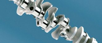
The sensor is located opposite the teeth of the drive disk. Sometimes it can be called synchronizing or reference. It is a disk with teeth along the outer circle. Can be mounted on a crankshaft pulley or flywheel and rotate with it at the same frequency.
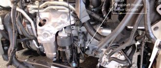
Where is the crankshaft sensor installed on Priora?
It is important for all Priora car owners to know where the DPKV is located. After all, the need to check or replace it may arise at any time, and therefore it is better to figure out where the sensor is located in advance. It is also recommended to purchase a new element and carry it with you in the glove compartment so that an unpleasant situation does not overtake you away from home.
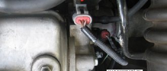
On a Priora, the crankshaft position sensor is located next to the oil filter on the oil pump cover. You can get to the device both from the engine compartment and from the inspection hole. The photo below shows where the DPKV is located on Priora.
Knowing its location is necessary in order to be able to quickly dismantle it for the purpose of inspection or replacement. When purchasing a new sensor, it is recommended to rewrite the designations on the standard product.
Construction types
The VAZ 2115 is equipped with two types of crankshaft sensors, which differ in design, but have the same principle of transmitting the read signal. The operation of any controller is based on two components:
- sensing element;
- toothed disc (synchro disc).
The master or synchro disk is installed on the crankshaft and has the same rotation speed with it. The disc rim is divided by 58 teeth, the empty space of two teeth is occupied by the synchronization point. The tracking element is located at a certain distance from the transverse axis of the disk, captures the moment of tooth transition and transmits the number of crankshaft revolutions to the computer.
According to the type of design, the sensors on the VAZ 2115 can be of the inductive type and based on the Hall effect. Optical sensors that use a light beam are rarely installed on cars, since the engine compartment is often highly dusty. There is a danger that the sensitive element of the light catcher will be clogged with grease, oil, etc.
The magnetic controller for VAZ is based on a core with a winding installed in a plastic case. The principle of signal transmission is based on the law of electromagnetic induction. On the winding of the core, when a part of the disk without a tooth passes next to it, there is no current; when a part of the disk with a tooth approaches, a magnetic field arises, the winding is excited, current induction appears, and a stable electrical signal is formed, which is transmitted to the ECU.
The advantages of the magnetic sensor are obvious: its operation does not require power from the on-board network. Accordingly, the risk of breakdowns is reduced; during diagnostics, only the condition of the winding, core and signal quality to the ECU are checked.
DPKV, the operating principle of which is based on the Hall effect, requires connection to the on-board network. The operation is based on the occurrence of voltage on two plates through which current passes.
The cost of controllers for the entire VAZ line starts from 200 rubles, so parts are not repaired, only replaced.
Example of operation of the crankshaft sensor VAZ 2110
For example, on engine 21124 of a VAZ-2112 car (16 valves, where the DPKV cable is located very close to the exhaust manifold), the problem usually arose after repairs, when the wires on the cable were not connected to the bracket. The cable melts on contact with the heat pipe, destroying the connection circuit, and the car stalls.
Another example could be a poorly made motherboard, the rubber cover of which may bend at the internal connections.
The ECU determines the position in relation to the crankshaft at any given time by calculating its speed and angular velocity after receiving a single signal from the throttle valve.
Using a sinusoidal signal from the crankshaft position sensor, you can solve a wide range of problems.
- Determining the position of the piston in the first (or fourth) cylinder at a given time.
- Control of injector injection time and duration of open state.
- Ignition timing control.
- Control of the variable valve timing system.
- Control of the fuel vapor absorption system.
- Operation of other auxiliary systems depending on engine speed (for example, electric power steering).
Therefore, DPVC plays an important role in maintaining engine performance by precisely determining the operation of two main systems - ignition and fuel injection.
Before purchasing a replacement on-load tap-changer, it is important to confirm the type of on-load tap-changer installed on the engine.
Functions and purpose of the crankshaft sensor VAZ 2110
On engines with 8 or 16 valves, the timing differential is not intended for control, but for determining the timing of gasoline injection. The VAZ 2110 crankshaft sensor also transmits an impulse to ignite the fuel-air mixture in the combustion chamber of the power unit. Therefore, a malfunction of the controller can lead to failure of the vehicle systems. This means that the engine will not work properly.
Crankshaft sensor VAZ 2112
The VAZ 2110 crankshaft sensor itself is an inductive device that should respond to the passage of teeth along the adjusting disk. This disk is installed on the generator pulley, and the regulator itself is installed next to it. The pulley has 58 teeth with a 2-teeth slot between them. This groove allows synchronization with the top dead center of the engine piston. The moment the slot passes through the controller, a corresponding signal is sent to the engine control unit.
There are quite a lot of designs of devices of this type, the operating principle of which is based on a regulator, for example, the VAZ 2110 Hall sensor. In the latter case, the regulator also responds to a rotating shaft, but is triggered by the passage of a permanent magnet.
Inductive (magnetic) crankshaft sensor VAZ 2110
The device is based on a magnetized core inside a coil. At rest, the magnetic field is constant and there is no self-induced electromagnetic field in the coil. When the metal toothed tip of the stationary disk passes in front of the core, the magnetic field around the core changes, resulting in an induced current in the winding. When the disk rotates, an alternating current is generated at the output, the frequency of which varies depending on the speed of rotation of the shaft. The work is based on the effect of electromagnetic induction.
A special feature of this sensor is its simple design, which allows it to operate without an additional power source.
Hall effect sensor
This type of sensor operates on a chip that is housed in a housing with magnetic field lines and a main disk that creates a moving magnetic field with magnetized teeth.
The sensor provides a highly accurate output signal in all specified crankshaft rotation modes. The Hall effect sensor requires a DC voltage connection.
Optical sensors
It is based on the physical phenomenon of the photoelectric effect. It consists of a light source with a receiver (photodiode). A perforated disk rotating between the light source and the receiver periodically closes and opens the path of the light source, after which the photodiode produces a pulsed current, which is sent as an analogue signal to the control unit (the system has limited application and was previously installed on ignition rollers in cars, for example, Matiz).
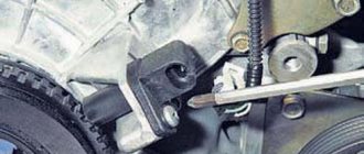
Where is?
If you find a problem with your engine, you need to know the position of the governor before you begin to determine the problem and signs of failure. Where is the crankshaft position sensor located on Tencent 8 or 16 valves? If you open the hood, you will find the regulator right on the oil pump cover. As you can see, the location of the regulator is not particularly convenient. VAZ engineers thought about this and the ease of replacing the regulator, so they equipped the DPKV with a wire 80 cm long.
DPKV under the hood of a car
How can I check the serviceability of the DPKV?
Nowadays, the most popular are 3 methods, which are carried out quickly and provide information about the performance of the sensor with high accuracy.
When measuring the resistance of a winding set on a sensor, you can use a special device - an ohmmeter (or in other words, a multimeter). When checking, the device should show a value in the range of 550-750 Ohms.
Testing process - the resistance of the coil in the inductive sensor is measured. If the coil on the sensor is damaged, then first of all the damage will be reflected in the resistance value. That is why, at the beginning of the diagnosis, the required range is set and the correct operation of the element is checked using probes.
This type of check is basic and most elementary, but it cannot give 100% confidence in the serviceability of the spare part.
Comprehensive diagnostics of the crankshaft position sensor
The second method of checking the sensor for functionality is considered more labor-intensive and requires a whole range of instruments that are only available in car repair shops. To carry out the work you will need:
- Megaohmmeter model;
- Special network transformer for data decryption;
- Standard sample of inductance meter;
- A regular digital voltmeter.
Using an ohmmeter, as before, we measure the resistance. Using an inductance meter, we measure the induction value on the winding. In good condition, the sensor gives a value of 250-400 mH. After this, we measure the insulation resistance value, which at a voltage of 500 V should be 20 MOhm. In this method, a network transformer is needed when periodic magnetization of the sensor occurs. If the sensor is in good condition, all received data should be within the established limits.
Diagnostics of the crankshaft position sensor signal using an oscilloscope
This method of diagnosing the crankshaft can be considered the most accurate, since not only the crankshaft component is checked, but also its design itself during operation of the machine. The point of the procedure is to connect an oscilloscope to the crankshaft position sensor and monitor the values emanating from it using a program. With this method, there is no need to remove the device from the engine - all work is carried out with the car running.
Functional testing steps:
- A black clamp, called a “crocodile” among experts, is connected to the engine ground of the vehicle being tested;
- Next, the probe probe is installed parallel to the signal terminals of the sensor itself (a characteristic connector with the terminal designated by the letter A);
- Then the second connector of the oscilloscope probe needs to be connected to the corresponding analog input of the computer where the program is installed;
- If all the component wires are correctly connected, you will see on the monitor screen the signal from the oscilloscope in the form of a graph with the signal voltage directly at the DCPV input;
- For analysis, you need to select a special mode for displaying the constructed oscillogram - it calls it “Inductive_Crankshaft”. After this, all that remains is to start the car engine and monitor the values received from the sensor.
If you receive a signal from a sensor whose output parameters do not correspond to normal values, you will be able to observe a sharp twitching of the machine’s motor, as well as difficulties when starting it. The presence of these violations when analyzing the output signal of the DCPV will indicate the occurrence of malfunctions:
- In the design of the sensor itself;
- In the element defining the synchronization disk;
- In the teeth.
Which part of the device ultimately became unusable can be understood only after analyzing the nature of the change in the waves of the device on the oscillogram. As a rule, it is not the sensor itself that needs to be replaced, but the gear wheel, which has become unusable during operation.
Checking the DPKV for serviceability
To confirm the suspicion of a faulty crankshaft sensor, the two most likely causes of damage are discussed.
In both cases, it is necessary to dismantle the device using a threaded wrench No. 10. Marking the crankcase and the sensor itself before starting work will help subsequently tighten the device to the initial angle of rotation. Before dismantling, the driver must also remember to measure the gap between the synchronizing disk and the sensor, which should not exceed 0.6 - 1.5 mm. If there is no mechanical damage, for example, scratches, dents, or damage to the material structure, the sensor is checked with another measuring device.
- Check with an ohmmeter. In this case, it is necessary to measure the resistance of the sensor winding. Since the standard values for this parameter are set by the manufacturer and range from 550 to 750 ohms, exceeding this limit means that there is a problem with this function, which is important for the proper functioning of the automotive device, and therefore it is faulty. It is worth noting here that the manufacturer allows very slight differences in resistance from the values indicated on the plate, but in any case they must correspond to the data specified in the vehicle's owner's manual.
- Check with a voltmeter, inductance meter and transformer. This method is more complex, but more effective: you measure the resistance with the same ohmmeter, and then check the inductance at a winding voltage of 500 volts (which should be between 200 and 4,000 mH). Then measure the resistance with a megohmmeter to make sure it is less than 20 megohms.
If the sensor still fails this test, it must be replaced. During this process, do not forget to maintain the distance specified by the manufacturer between it and the timing disk and align it with the marks on the crankcase of the previous unit. The new sensor must be tested before installation as it may not function properly even if all installation procedures have been followed correctly.
The new DIC is tested in the same way as the one suspected of being faulty and, depending on the results, the device may be replaced or rejected. During installation, the bolts should be tightened to a torque of 8-12 Nm. In any case, before taking any action to replace a rather expensive and hard-to-find component, you must make sure that it is the one that is faulty, since cars produced by our automotive industry are prone to unpleasant surprises.
First way to check
In this case, you will need an ohmmeter with which you can replace the resistance on the winding. The value ranges from 550 to 750 ohms according to manufacturer standards.
If your values are a little different from generally accepted ones, that's okay. However, if the deviation is severe, you will definitely have to replace the sensor.
To be fair, it is worth noting that the crankshaft position sensor on VAZ 2110 models rarely fails. The main reasons for the disruption of its normal functioning are the accumulation of dirt, mechanical damage and ordinary factory defects.
Features of testing on other cars
As for other cars, for example, VAZ-2109, VAZ-2112 and VAZ-2114 with injection engines, they are checked in the same way as VAZ-2110 cars.
It is worth noting that for a VAZ, an additional check can be carried out when checking the resistance of the crankshaft sensor coil.
To do this, however, switch the multimeter to voltmeter mode with a measurement limit of 200 mV.
Then connect the probe to the DDCV terminals and move any metal object, such as a screwdriver, close to the core.
If the sensor is working properly, it will react to metal and a voltage spike will appear on the multimeter display. If there are no such spikes, this indicates a faulty component.
As for a car like the Renault Logan, the difference between it and the VAZ comes down to a slightly different reading of the resistance of the sensor coil when measured with an ohmmeter.
In a full Logan ECB, the normal resistance is 200-270 Ohms.
The coil resistance in a Daewoo Lanos car should be in the range of 500-600 Ohms.
However, on ZMZ-406 engines installed on Volga and Antelope cars, the normal coil resistance is 850-900 Ohms.
Second method
Here you will need a voltmeter, a transformer and an inductance meter. It is best to measure resistance at a compact temperature.
After receiving the ohmmeter reading, arm yourself with an inductance meter. Typically the meter should read between 200 and 4000 units (milligener).
When 500 volts is applied to the crankshaft position sensor winding, the megger measures the resistance. Under normal conditions, the readings will be no more than 20 megaohms.
Controller diagnostics
Diagnostics of the crankshaft position sensor is carried out on the dismantled controller. It is recommended to set a timing mark on the crankcase before removing it so that when installing a new element, the correct gap between the tracking device and the timing disk will be maintained. The permissible gap is 0.6–1.5 mm.
We remove the element with a 10mm wrench and carry out a visual inspection. Before checking the crankshaft sensor, the battery is disconnected and the contact points are checked. During a visual inspection, the integrity of the housing, wires, connectors, and the absence of cracks and dents on the housing are checked. If there are no signs of mechanical damage, the DPKV is checked with a multimeter.
Testing of the node can be carried out both by resistance and voltage parameters. Testing for resistance is much simpler, so it is used in most diagnostic options.
The resistance on the working controller winding should be in the range of 550–750 Ohms. Measurements are taken on two contacts of the part. For a 16-valve injector engine, a resistance deviation of 5% is considered acceptable.
Drivers rarely use the second testing option, although diagnostics with a voltmeter are considered more reliable. To check, you will need a transformer and an inductance meter, for example, the MY-6243 multimeter model is often used to measure capacitance and inductance. Checking step by step.
- Calculate the inductance dpkv. The working element at a voltage of at least 500 mV will show an inductance in the range of 200–4000 iH.
- Check the resistance; a working sensor shows a parameter of 20 mOhm.
Important points
Drivers note that not all sensors that have a suitable mounting size are suitable for working on a VAZ 2110. You can only replace the sensor with an original one, after first checking the part for functionality. A resistance test must be carried out before installation on a car; according to statistics, 1–3% of VAZ sensors have manufacturing defects.
The equipment can be considered operational only after a preliminary manual check with an ohmmeter. Things to consider.
- Be sure to mark the pulley when reinstalling the part. The ideal option would be to check with a scanner that the sensor is installed correctly. Any displacement of the crankshaft will lead to disruption of the fuel supply phases.
- Observe the sensor pinout. Select equipment with suitable terminal tolerances.
- Tighten the fastening bolt to a torque of 8–12 nm, do not overtighten.
- Leave a gap between the controller and the transfer disk.