Not good afternoon. I'm glad that we are on the move, the car sometimes stalls, the upper check light comes on and does not start. Jerking the battery terminal returns it to operation and you can get somewhere (no errors are displayed), there is no loss of traction. I came across a note on the Internet: (The error “P0336 crankshaft position sensor circuit, signal out of acceptable ranges” is not often encountered on domestic cars. Unlike “P0335 there is no signal from the crankshaft sensor”, with 336 everything is not as simple as it might seem I will try to consider all possible reasons for this code.
Code P0336 is set if -The crankshaft rotates -For one rotation of the crankshaft, the controller determines the displacement of the reference mark. That is, interference appears in the signal from the crankshaft sensor, which the controller may mistakenly identify as missing teeth. As a result, the synchronization is lost, the engine begins to spontaneously jerk, stall, and stall. False misfire errors P0300 may be recorded. Let's look at the reasons why this code may appear. 1. Broken contacts in the sensor or controller block can cause the intermittent code P0336 to be entered. 2. Also, damage to the wiring and screen to the crankshaft sensor can cause the intermittent appearance of this code. 3. Damage to the drive disc on the crankshaft pulley. 4. The crankshaft sensor itself. Its resistance should be about 700 Ohms. For a full check, you will need a multimeter, an oscilloscope and a keen eye. The most common cause of a P0336 code is damage to the wiring to the crankshaft position sensor. Often, a loose harness dangles under the hood and once it touches the hot exhaust manifold, it melts and becomes damaged. ) ___________________________________________________________________________________ In the evening I’ll go look, wash, search. Who can advise in this regard regarding our glorious car (problem areas, advice on where to wash, what to scrape, where to shake)))
Ps. I’ll supplement the note with photographs of the places I’ll visit)))
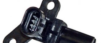
The crankshaft sensor is designed to synchronize the operation of the ignition system and fuel injectors. If the device fails, the stability of the fuel supply is disrupted, or the fuel supply is completely stopped, which can cause the engine to stop working and be unable to start it again.
A working sensor allows the microcontroller to determine the position of the pistons in the cylinders. The crankshaft has a gear with two missing teeth. When passing near the sensor, the teeth distort its magnetic field, resulting in the formation of special pulses in the inductor. The missing teeth are the starting point for the microcontroller to determine the initial position of the crankshaft. The computer automatically counts the number of pulses passing from the sensor, and also determines the position of the crankshaft, on the basis of which the time for operation of the ignition system and fuel injectors is calculated.
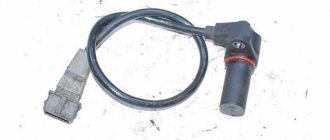
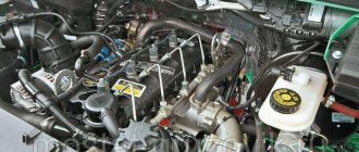
The sensor is located in a bracket that is installed in the area of the generator drive pulley. It is mounted with a small gap in the area of 1-1.2 mm near the toothed pulley. This location is very inconvenient for penetration, because a 70 cm long wire with the necessary connectors is attached to it. To set the required position, adjustment of the washers between the mounting socket of this element is required.
There are a number of vehicle errors that may indicate sensor failure, namely:
- A rapid decrease in machine power, which is determined physically, without the use of measuring and diagnostic devices.
- Arbitrary decrease or increase in engine speed.
- Detonation during dynamic load in the engine.
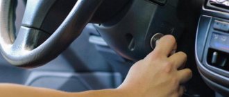
- The engine does not start when turning the key.
- When the vehicle is idling, unstable engine speed occurs.
- Complete absence of vehicle idling.
At the same time, it is not necessary to contact specialists if you need to make sure that the crankshaft sensor is faulty; you can do this yourself. To do this, you can use several available options, which differ in the type of devices used.
Perhaps one of the simplest diagnostic methods involves preliminary dismantling of the device being tested. To do this, you must first make marks about the initial position of the sensor. It is also recommended to check the gap between the synchronization disk and the core. The size of this gap should be in the range from 0.6 to 1.5 mm.
After dismantling, it is necessary to check the sensor for visible damage. To better examine the device, the meter along with its contacts is recommended
Wipe thoroughly with a cloth soaked in alcohol. If a visual inspection does not reveal any damage or malfunctions, then it is necessary to proceed to checking the electrical circuit.
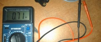
Diagnostics requires checking the winding resistance on the coil using an ohmmeter. If a number in the range of 550-700 Ohms is displayed on the device’s display, this indicates that the sensor is working properly. If the device shows different numbers, or the device does not respond to measurements at all, then the crankshaft position meter is faulty.
There is also a more thorough testing technique that examines:
- winding resistance;
- insulation resistance;
- magnetization of the meter.
To perform such diagnostics, it is necessary to use special equipment, including: a megger, a network transformer, a digital voltmeter, and an inductance measuring device.
It is important to know that the changes will be more accurate and relevant if they are carried out at an ambient temperature of no higher than 20 degrees Celsius.
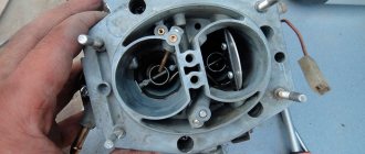
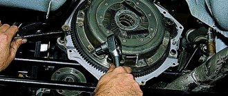
If the check does not reveal any problems with the sensor, then you need to move on to examining the pulley. In some cases, the problem is that the pulley is not seated tightly on the shaft. This may cause the meter to send incorrect pulses. Another common cause of the problem is a toothed wheel, in some cases one or more teeth may break off.
However, in practice, it is extremely rare to get to the point of in-depth testing of the sensor. In most cases, to identify a malfunction, it is sufficient to carry out the previously described simple diagnostics with visual inspection and the use of an ohmmeter.
Greetings, dear friends, in today’s article we will talk to you about the ZMZ 409 crankshaft sensor, consider the technical characteristics, and find out how to check its working condition.
Technical characteristics and operating principle
Bosh crankshaft position sensor 0 261 210 331 inductive type, cable length 710 mm. Resistance between contacts 1-2: 0.86 – 0.90 kOhm. If there is a malfunction, it displays errors: 0335. There is no signal or a fault in the crankshaft position sensor circuit.
The crankshaft sensor ZMZ 409 or Bosh 0 261 210 331 is installed on the UAZ Patriot and other models of inverter cars from the Gas plant.
DPKV sends signals to the electronic control unit about the speed and position of the crankshaft. The signal is a series of low voltage electrical pulses.
This signal is the reference signal for the control unit and the ECU, based on these signals, generates control pulses for the injectors and ignition coils. That is, if we do not have the crankshaft sensor sending impulses to the ECU, then the control unit, in turn, will not supply fuel and spark to the ignition coils.
Engine crankshaft position sensor (synchronization sensor) device
The crankshaft sensor (DPKV) 405, 406, 409, 4213, 4216 engine consists of:
- Housing - plastic or aluminum with receptive part
- Sensory lobe - made of a magnetic core and a copper wire solenoid on an insulating reel
- Flange - oval with hole for M6 bolt
- Communication wire - shielded, 610 mm long
- The connecting plug of the wire is three-pin, crimped with the wire.
Design options:
- The wire output of the domestic crankshaft position sensor is rotated 900 with respect to the line of the mounting hole.
- The wire outlet of the imported crankshaft sensor is oriented in the other direction from the mounting hole.
Article about camshaft sensor
How to check the crankshaft sensor ZMZ 409
Checking the ZMZ 409 crankshaft sensor occurs as follows:
- We take a simple tester and place the measuring bar on the diode and start ringing the contacts.
- We take the first and second contacts and check the resistance. During normal operation, the resistance is between 650 and 750 ohms.
- Now we check the sensor for inductance. You can find out how to do this by reading this article.
Replacement and repair of crankshaft sensor ZMZ 409
If after checking you need to replace the crankshaft sensor, you must do the following:
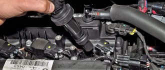
- Using a 10mm wrench, unscrew the bolt securing the sensor to the engine block.
- Remove the sensor from the hole. Having unbent the sensor wire fastening clamps located on the intake manifold and cylinder block, pull the wire together with the connector down. Install the sensor in reverse order.
- After installing the sensor, use a set of feeler gauges to check the gap between its rod and the teeth of the synchronization disk. The gap should be within 1-1.5 mm.
Well, that’s basically all I wanted to tell you about the ZMZ 409 crankshaft position sensor.
Sensors of the UAZ Patriot engine management system
Home • UAZ • Patriot • Electrics
The UAZ Patriot coolant temperature and air temperature sensors in the intake pipe, type 19.3828, are a thermistor (a resistor whose resistance changes depending on the temperature). The coolant temperature sensor is screwed into the thermostat housing and connected to the controller input, which is connected to an internal 5 V source through a 2 kOhm resistor. At low temperatures the sensor resistance is high, at high temperatures it is low. The controller calculates the coolant temperature based on the voltage drop across the sensor. On a cold engine the voltage drop is high, on a warm engine it is low. Coolant temperature affects most of the characteristics controlled by the controller.
To replace the UAZ Patriot temperature sensors for coolant and air temperature in the intake pipe, you will need a 19 key. Disconnect the wire from the minus terminal of the battery and partially drain the coolant from the radiator
Disconnect the wiring harness block from the sensor connector by unfastening the spring lock and unscrew the sensor from the thermostat housing
And the air temperature sensor from the intake manifold
Checking the UAZ Patriot temperature sensor circuit: 1 – variable resistance 10 kOhm; 2 – battery; 3 – voltmeter; 4 – milliammeter; 5 – sensor.
To test the sensors, you need to assemble a circuit. Using resistance 1 using milliammeter 4, set the current in the circuit to 1–1.5 mA. At a temperature of +25 °C, voltmeter 3 should show a voltage of 2.957–3.022 V. By changing the ambient temperature of the sensor, measure the value of the voltage drop with voltmeter 3. For a working sensor, it should be within the following limits: at a temperature of 40 °C – 2.287–2.392 V; at a temperature of 90 °C – 3.642–3.737 V. Replace the faulty sensor. Install the Patriot temperature sensors in the reverse order of removal. When installing the coolant temperature sensor, lubricate its threads with sealant
Crankshaft position sensor UAZ Patriot
The crankshaft position (synchronization) sensor type DG-6 0261210113 from Bosch or 23.3847 inductive type is designed to determine the angular position of the engine crankshaft, synchronize the operation of the controller with the engine operating process and determine the crankshaft rotation speed.
UAZ Patriot crankshaft position sensor diagram: 1 – sensor winding; 2 – body; 3 – magnet; 4 – seal; 5 – drive; 6 – mounting bracket; 7 – magnetic circuit; 8 – synchronization disk.
Structurally, the sensor is a bar magnet 3 on which winding 1 is mounted. When the teeth of the synchronization disk 8 pass past the end of the magnet, a potential arises at the winding terminals, which is information for the controller about the crankshaft speed. Two teeth on the disk are missing; when the cavity on the disk passes past the magnet, a pulse is generated, by which the controller determines that the piston of the 1st cylinder is at TDC.
If the timing sensor or its circuits fail, the operation of the ignition system and, consequently, the engine stops. The sensor can first be checked directly on the engine. For final inspection, the sensor must be removed from the engine. To replace the Patriot crankshaft sensor you will need: a thin screwdriver, a 10mm wrench, and an auto tester. Turn off the ignition and disconnect the wire from the negative terminal of the battery
Press the spring clamp of the block and disconnect the synchronization sensor connector, then connect one probe of the tester, turned on in ohmmeter mode, to the central terminal of the sensor wiring harness block, and the second probe to any side terminal. The sensor winding resistance should be 700–900 Ohms
For a final check, remove the sensor by bending the clamps securing its wiring harness to the intake pipe and cylinder block, pull the harness down, unscrew the mounting bolt and remove the sensor from the hole in the engine cylinder block
Connect a tester turned on in voltage measurement mode to the sensor terminals. Quickly bring a metal object (such as tweezers) to the sensor core. If the sensor is working properly, there will be a voltage surge on the device. If the voltage does not change, the sensor is faulty and needs to be replaced. Install the UAZ Patriot crankshaft sensor in the reverse order of removal. After installing the sensor, check the gap between its core and the teeth of the timing disk. It should be 1–1.5 mm.
Camshaft position sensor UAZ Patriot
Camshaft position sensor (phase sensor) type PG-3.1 0232103006 Bosch, or 406.3847050-04, or 406.3847050-05, or DF-1 is installed in the left rear part of the cylinder head. Its action is based on the Hall effect. Using the information from this sensor, the controller determines the moment when the piston of the 1st cylinder is installed at TDC of the compression stroke to calculate the fuel injection sequence according to the operating order of the cylinders.
If the Patriot valve timing sensor fails, the controller turns on a warning light in the lamp block and switches from the phased injection mode to the backup mode of supplying fuel to all cylinders simultaneously. In this mode, fuel consumption increases significantly, so a faulty phase sensor must be replaced as soon as possible.
To replace the sensor you will need: a thin screwdriver or an awl, a 10mm key. Turn off the ignition and disconnect the wire from the negative terminal of the battery
After unfastening the spring lock, disconnect the connectors of the phase sensor wiring harness. Remove the sensor wiring harness block from the metal holder
Unscrew the mounting bolt and remove the sensor from the hole in the cylinder head
Scheme for checking the Patriot phase sensor: 1 – sensor; 2 – plug block; 3 – resistor 0.5–0.6 kOhm; 4 – LED AL307; 5 – metal plate.
Assemble a circuit to test the Patriot camshaft sensor and connect the wires to the battery terminals. LED 4 should light up and go out immediately. Move tweezers or a screwdriver near the sensor rod. If the sensor is working properly, the LED should light up briefly. If the LED does not light, the sensor is faulty and must be replaced. Install the sensor in the reverse order of removal.
Air flow meter UAZ Patriot
The UAZ Patriot mass air flow sensor type HFM5-4.7 0280218037 from Bosch, or 20.3855 from Siemens, or 406.1130000-01 is located between the air filter hose and the intake pipe hose. The sensor signal is a DC voltage whose value depends on the amount and direction of air flowing through the sensor. The sensor has a built-in air temperature sensor, the sensitive element of which is a thermistor installed in the air flow. At low temperatures the sensor resistance is high, at high temperatures it is low
Air temperature sensor resistance versus intake air temperature
If the Patriot air temperature sensor is faulty, the controller stores an error code in memory and turns on the warning light; the controller replaces the readings of the faulty sensor with a fixed air temperature value of 33 °C. To replace the sensor you will need: a 10mm wrench, a Phillips-blade screwdriver. Disconnect the wire from the negative terminal of the battery
Using a screwdriver or finger, press the plastic latch from below and disconnect the wiring harness block from the mass air flow sensor. Loosen the hose clamps
Remove the hoses from the sensor, and then the UAZ Patriot air flow sensor. Install the sensor in reverse order. Pay attention to the condition of the rubber gasket, as damage to it can lead to interruptions in engine operation.
Throttle position sensor UAZ Patriot
The throttle position sensor type 406.1130000-01 or DKG-1 0280122001 manufactured by Bosch is a potentiometer with a current-collecting element moving along the radius of the current-carrying sector from 0 to 100°. To check the Patriot throttle position sensor you will need: an auto tester and a screwdriver. Disconnect the wire from the negative terminal of the battery
Disconnect the wiring harness block from the sensor and measure the resistance between terminals “1” and “2” of the sensor block. For a working sensor it should be about 2 kOhm. Connect the autotester to pins “2” and “3”. When the throttle valve is open, the resistance should be 0.7–1.38 kOhm, when closed - 2.6 kOhm
To replace a faulty Patriot throttle position sensor, remove the two screws securing it and remove the sensor. Install the new sensor in the reverse order of removal.
Knock sensor UAZ Patriot
Knock sensor 02612311046 made by Bosch, or GT 305, or 18.3855 is installed on the engine block on the right side under the intake manifold in the area of the 4th cylinder.
Patriot knock sensor diagram: 1 – plug; 2 – insulator; 3 – body; 4 – nut; 5 – elastic washer; 6 – inertial washer; 7 – piezoelectric element; 8 – contact plate.
The knock sensor on the Patriot is a piezoelectric device that senses vibrations in the block wall caused by shock waves during detonation in the cylinders. Detonation is the explosive self-ignition of the working mixture in the engine cylinders. During detonation, voltage pulses are generated at the sensor output, which increase with increasing intensity of detonation impacts. The controller, based on the sensor signal, adjusts the ignition timing to eliminate fuel detonation flashes. If the sensor or its electrical circuits fail, the controller signals the driver by turning on the lamp and switches to a backup engine control mode with a late ignition timing. This mode is characterized by reduced engine power and increased fuel consumption, so the sensor must be replaced as soon as possible. To check, you need to remove the knock sensor from the car.
To remove and check the knock sensor you will need: a thin screwdriver or awl, a key number 13. Turn off the ignition and disconnect the wire from the negative terminal of the battery
Remove the heater hose from the holder on the sensor bolt. Disconnect the wiring harness connector from the sensor terminals by unfastening the spring lock of the block
Unscrew the nut, remove the heater hose bracket from the stud screwed into the wall of the cylinder head, and remove the sensor from the stud. Connect an autotester turned on in voltage measurement mode to the sensor terminals. Tap the sensor body with a hard object (for example, tweezers) - the voltage should change. If the voltage remains constant, the sensor is faulty and needs to be replaced. Install the UAZ knock sensor in the reverse order of removal.
Lambda probe UAZ Patriot
The Patriot oxygen concentration sensor type 5WK9-1000G from Siemens is used in a fuel injection system with feedback. The sensor is installed in the exhaust pipe of the exhaust gas system. To adjust the calculations of the duration of injection pulses, information about the presence of oxygen in the exhaust gases is used; this information is provided by the oxygen concentration sensor. The oxygen contained in the exhaust gases comes into contact with the oxygen concentration sensor, creating a potential difference at the sensor output. It varies from approximately 0.1 V (high oxygen - lean mixture) to 0.9 V (low oxygen - rich mixture). For normal operation, the temperature of the sensor must be at least 300 °C, therefore, for rapid warming up after starting the engine, a heating element is built into the sensor.
By monitoring the output voltage of the Patriot lambda probe, the controller determines which command to adjust the composition of the working mixture to send to the injectors. If the mixture is lean (low potential difference at the sensor output), then the controller gives a command to enrich the mixture; if the mixture is rich (high potential difference) - lean the mixture. To replace the control oxygen concentration sensor, you will need a 22 key. Disconnect the wire from the minus terminal of the battery
Disconnect the sensor block and the wiring harness by pressing the plastic latch, then unscrew the sensor from the exhaust pipe and remove it from the car. Install the sensor in the reverse order of removal.
Purpose, device and principle of operation
The crankshaft position sensor is the main regulating function of the fuel injection system on a vehicle. Its presence ensures synchronous operation of each engine injector and the entire ignition system.
The driver consists of the following components:
Unstable operation of the controller causes temporary interruptions in the fuel supply. During operation of the device, the vehicle control module, which is a microcontroller, ensures the correct piston position at a given time for each cylinder of the internal combustion engine.
To ensure adjustment using the device, the process is based on the following algorithm:
- The crankshaft of the power unit is equipped with a special gear. There are no two gears on it, this was done on purpose.
- When the machine's engine crankshaft begins to move, all the teeth move in close proximity to the controller. This contributes to strong distortions of its magnetic field.
- Signals are generated in the induction coil of the regulator when the shaft moves. Packet pulses are transmitted to the information base, which is located in the memory of the microcontroller. The two gears missing from the shaft are considered the starting point and also the zero point. Due to the absence of these gears, the microprocessor unit diagnoses the initial position of the crankshaft.
- The microprocessor in the car then counts the number of signals sent by the device. Then, after a certain time, the position of the crankshaft is determined.
- The processed pulse data is then sent by the control unit to the controller used to activate the fuel injector. The latter supplies fuel to the ignition system.
If the crankshaft position sensor is working properly, the vehicle's engine will operate at maximum power. The drive unit will require a minimum amount of fuel to achieve maximum power.
Types of sensors
It is worth discussing separately the different types of devices:
- Magnetic induction DPKV. Devices of this type do not require a separate battery for power. The voltage value at a certain time is initialized for the control module pulse. This occurs when the timing gear passes through a magnetic field. A magnetic field appears around the regulator, and the device itself controls the speed of rotation of the shaft and can be used as a speed regulator.
- Hall driver, its operation is based on the Hall effect. This indicates that the current transmission begins when the variable field is applied to the device. The synchronizer roller itself engages the field using gears that influence the field generated around the controller. Hall effect control unit used as ignition distributor.
- Optical type device. This type of driver includes a shaft that synchronizes with holes or teeth. The target causes an overlap of the light flux between the diode element and the receiver. The latter converts the received light flux into a signal. As a result, voltage is applied to the microprocessor module.
Main symptoms of DPKV malfunction
A faulty sensor or a faulty device sensor can be recognized by the following symptoms:
- The vehicle's propulsion system began to detonate. When the engine is idling or increasing engine speed, a knocking sound occurs from the hydraulic compensators. The so-called pins may knock when driving uphill at low engine speeds.
- The car engine is no longer as stable as before. The engine speed may drop sharply at idle or shift to a higher speed. A car can become stuck idling if it is stuck in traffic or at stop lights.
- The drive may not rotate at the correct speed even if it is running at maximum power.
- The machine's engine power may drop and then increase. In this case, the driver will not take any action.
- The aerodynamic properties and characteristics of the machine are significantly deteriorated.
- The generator may not start. The engine may not start or may catch fire and shut down suddenly.
- No spark when ignition. It may not appear at all or occur with a certain frequency.
If the vehicle owner detects three or more “symptoms” of an internal combustion engine malfunction, the device must be replaced.
It should be noted that the described malfunctions do not always indicate a controller malfunction. They may also indicate other problems with the drive. For example, a sharp change in engine power and a drop in speed indicates a clogged fuel pump or lines connected to it. Symptoms of incorrect operation of the combustion chamber may appear due to contamination of the sensor connection socket.
The Govorun4eg Auto channel showed signs of a faulty high pressure control valve in practice.
How to check DPKV for performance?
You can check the operation of the DPKV in three ways:
Diagnostics of the crankshaft position sensor with an ohmmeter
You can use an ohmmeter to test the regulator winding to measure the resistance value. If an ohmmeter is not available, multimeters can be used. As a result of diagnostics, on a working sensor the resistance value should be in the range of 550-750 Ohms.
The testing process itself consists of measuring the resistance of the inductive regulator coil. If this equipment fails, the failure will affect the operating resistance parameter. Therefore, before starting the test, you should set the appropriate range and diagnose the correct operation of the device using measuring sensors.
The method of checking the crankshaft sensor with an ohmmeter is considered the simplest to perform, but does not give a 100% result.
Nikolay Vaganov demonstrated the procedure for diagnosing the crankshaft sensor using a multimeter.
Comprehensive diagnostics of the crankshaft position sensor
If there is any sign of a faulty crankshaft sensor, a sophisticated test method can be used. This diagnostic method is complex in execution, but more accurate. To manufacture it, you will need a set of devices and accessories that are not available at every service station.
To complete the task you will need:
- megohmmeter;
- a network conversion device that will be used to decode information;
- A traditional example of an inductance meter;
- Multimeter or digital voltmeter.
When conducting a comprehensive diagnosis of the crankshaft sensor, it is recommended to maintain the temperature within 20-22 degrees. This condition is necessary to ensure the correct values will be output by the device.
Features of complex device diagnostics:
- Using an ohmmeter or other tester, the operating resistance value is diagnosed.
- The amount of inductance is measured on the regulator winding by inductance. If the sensor The obtained value should be in the range of 250-400 mH.
- Then a procedure is carried out to measure the resistance of the insulating layer. When a voltage of 500 V is applied, the operating parameter value should be approximately 20 mOhm. A mains transformer will be required in case of periodic magnetization of the regulator. If the device is working properly, all values obtained from the test will be within the specified limits.
Diagnostics of the crankshaft position sensor signal using an oscilloscope
This diagnostic option is the most accurate of all those described. This is because not only the crankshaft element is checked, but also its design during engine operation. The essence of diagnostics is to connect an oscilloscope to the controller and monitor the signals using icons that extend from it. During the test, it is not necessary to disconnect the sensor from the drive, since all operations will be performed with the engine running.
- The wire with the black terminal connects to the vehicle's powertrain ground or ground.
- The bayonet probe is then installed on the signal pins of the controller itself. The connection occurs in parallel. To identify the output signal, the corresponding connector must be marked with the letter A.
- The next step is to connect the second probe of the diagnostic tool. The connector connects to the analog input via a computer or laptop. The software must be previously installed and configured on the other device.
- When all electrical circuits are connected correctly, the oscilloscope signal will appear on the computer screen. It will be plotted as a graph. The pulse voltage is set at the input of the controller being diagnosed.
- To diagnose the device, you must specify a special graph output mode. This mode is called inductive crankshaft. After setting all parameters, the installation starts. Then all controller parameters are monitored.
If a pulse is received from the controller that does not correspond to the nominal parameters, the generator will clearly twitch. It may be difficult to start the engine.
The appearance of such malfunctions when monitoring output pulses from the controller will indicate the following problems:
- defects in the controller design;
- damage to the element designed to interact with the synchronizer shaft;
- malfunctions in the functioning of the dentition.
The Car Diagnostics channel talked about the features of testing DPKV using a pocket oscilloscope.
Where is the crankshaft sensor located on the 405, 406, 409, 4213, 4216 engine?
This section indicates the location of the engine crankshaft position sensor (DPKV) 405, 406, 409, 4213, 4216. The specific installation point for the device is presented.
On the 405, 406, 409 engine, the crankshaft sensor is mounted in the front of the heart of the car, on the right, below on the protrusion of the front cover of the cylinder block. Attached with M6 hardware under head 10. The normal gap between its end and the tooth of the synchronization disk should be 0.5-1.2 mm. For stable operation, set the gap to 0.8 mm. To do this, you need to sand the device seat with sandpaper. The crankshaft sensor 405, 406, 409 of the engine is connected to a bundle of wires using a three-pin socket with a frame spring.
Where is the DPKV installed on the UMZ 4213, 4216 engine?
The location of the crankshaft position sensor on 4213, 4216 engines is located in the front part, on the right, on the flange of the camshaft gear cover. The nominal gap between the end of the device and the tooth of the synchronization disk is in the range of 0.51-2 mm.
Article about throttle sensor
How to replace DPKV?
To facilitate the disassembly and adjustment procedure or replacement of the controller, a 50-70 cm long wire is connected to it. This line is equipped with special key covers. To adjust the position of the controller, adjust the washer attached to the seat of the device. The procedure for adjusting this washer can be carried out in a workshop or at a service station. Correct adjustment will allow you to avoid rapid breakdown of the aggregate cylinders and reduce fuel consumption.
Algorithm of actions for exchanging controllers:
- The controller is disconnected from voltage; to do this, disconnect the plug using the device's wiring.
- Using a wrench, unscrew the screw that secures the device to the installation site.
- The driver himself has been dismantled.
- An undamaged controller must be placed in its place. The locking device is screwed back. The plug with wires is connected.
- After installing the controller, a gap measurement test must be performed. Pocket between the teeth of the generator drive command and check the regulator core. The TENTETTE kit is used to measure this parameter. The gap size should be between 0.39 and 0.41 mm, preferably 1 mm.
If diagnostics show that the clearance differs from the required value, adjust the position of the controller. Or you need to get rid of existing pollutants. After replacement, start the combustion engine and check for proper operation.
Good afternoon. In today's article, I have collected for you all the signs of a faulty crankshaft position sensor.
Traditionally for our site, the article contains many photos and video materials.
What is the crankshaft position sensor for and how does it work?
The crankshaft position sensor is used to determine the angle of rotation of the crankshaft at a given time.
This is the only sensor without which the engine will not work.
It looks like this:
The crankshaft position sensor works in conjunction with a timing disc on a pulley or flywheel. The sync disk looks like this:
The crankshaft position sensor itself is a wire coil on a magnetic core.
When the synchronization disk rotates, the metal plates periodically approach and separate from the core, due to this the magnetic field strength changes, and an electric current is induced in the sensor coil.
If we connect the output signal of the sensor to an oscilloscope, we will see this picture:
This signal is sent to the engine control unit, and it in turn issues commands to supply a spark to the cylinders and open the injectors.
Although the sensor is a simple device, since it operates under difficult conditions (vibration, temperature changes), it sometimes fails. It is known that a sensor malfunction is not always obvious.
Signs of a malfunctioning crankshaft position sensor.
The engine does not start.
As already written above, DPKV is the only sensor without which the engine will not start.
If, when you turn the key in the ignition switch, the starter quickly turns the engine and the fuel pump hums, with a high degree of probability we can say that the problem is in the crankshaft position sensor.
The fact is that the engine control unit, not receiving a signal from this sensor, does not know in which cylinder to give a spark and in which to open the injector.
The sensor is checked using diagnostics or by replacing it with a known good one.
The engine suddenly stalls when hot.
This happens completely randomly. The engine warmed up to a certain temperature and stalled.
It stood and started up..... 5-10-20 minutes passed and everything started again.
The author of the article personally encountered such a manifestation of failure of the crankshaft position sensor.
Since I had the elm 327 diagnostic with me, I immediately understood what was wrong, but it was impossible to solve the problem, since there was still no spare sensor.....
After the car sat for 30 minutes it started as if nothing had happened.
As a result, we drove to the city, watering the sensor with water from a bottle every 10 minutes.
The cause of this malfunction is a microcrack in the sensor winding, which diverges due to thermal expansion.
The engine does not start in cold weather.
How to find out if the crankshaft sensor is faulty?
The crankshaft sensor is designed to synchronize the operation of the ignition system and fuel injectors. If the device fails, the stability of the fuel supply is disrupted, or the fuel supply is completely stopped, which can cause the engine to stop working and be unable to start it again.
A working sensor allows the microcontroller to determine the position of the pistons in the cylinders. The crankshaft has a gear with two missing teeth. When passing near the sensor, the teeth distort its magnetic field, resulting in the formation of special pulses in the inductor. The missing teeth are the starting point for the microcontroller to determine the initial position of the crankshaft. The computer automatically counts the number of pulses passing from the sensor, and also determines the position of the crankshaft, on the basis of which the time for operation of the ignition system and fuel injectors is calculated.
The sensor is located in a bracket that is installed in the area of the generator drive pulley. It is mounted with a small gap in the area of 1-1.2 mm near the toothed pulley. This location is very inconvenient for penetration, because a 70 cm long wire with the necessary connectors is attached to it. To set the required position, adjustment of the washers between the mounting socket of this element is required.
There are a number of vehicle errors that may indicate sensor failure, namely:
- A rapid decrease in machine power, which is determined physically, without the use of measuring and diagnostic devices.
- Arbitrary decrease or increase in engine speed.
- Detonation during dynamic load in the engine.
- The engine does not start when turning the key.
- When the vehicle is idling, unstable engine speed occurs.
- Complete absence of vehicle idling.
At the same time, it is not necessary to contact specialists if you need to make sure that the crankshaft sensor is faulty; you can do this yourself. To do this, you can use several available options, which differ in the type of devices used.
Perhaps one of the simplest diagnostic methods involves preliminary dismantling of the device being tested. To do this, you must first make marks about the initial position of the sensor. It is also recommended to check the gap between the synchronization disk and the core. The size of this gap should be in the range from 0.6 to 1.5 mm.
After dismantling, it is necessary to check the sensor for visible damage. To better examine the device, the meter along with its contacts is recommended
Wipe thoroughly with a cloth soaked in alcohol. If a visual inspection does not reveal any damage or malfunctions, then it is necessary to proceed to checking the electrical circuit.
Diagnostics requires checking the winding resistance on the coil using an ohmmeter. If a number in the range of 550-700 Ohms is displayed on the device’s display, this indicates that the sensor is working properly. If the device shows different numbers, or the device does not respond to measurements at all, then the crankshaft position meter is faulty.
There is also a more thorough testing technique that examines:
- winding resistance;
- insulation resistance;
- magnetization of the meter.
To perform such diagnostics, it is necessary to use special equipment, including: a megger, a network transformer, a digital voltmeter, and an inductance measuring device.
It is important to know that the changes will be more accurate and relevant if they are carried out at an ambient temperature of no higher than 20 degrees Celsius.
If the check does not reveal any problems with the sensor, then you need to move on to examining the pulley. In some cases, the problem is that the pulley is not seated tightly on the shaft. This may cause the meter to send incorrect pulses. Another common cause of the problem is a toothed wheel, in some cases one or more teeth may break off.
However, in practice, it is extremely rare to get to the point of in-depth testing of the sensor. In most cases, to identify a malfunction, it is sufficient to carry out the previously described simple diagnostics with visual inspection and the use of an ohmmeter.