Avto-Science.ru
Lubrication system
with a dry sump (common name - dry sump) is designed to ensure stable operation of the lubrication system in all positions of the vehicle, incl. during sharp maneuvers at high speed, large tilts in vehicles. Thanks to these qualities, the lubrication system
dry sump is used on sports cars, tractors and some off-road vehicles. The system involves storing oil in a separate tank and pumping it into this tank with a separate pump (pump section). In this case, the oil sump always remains without oil - the so-called. dry sump.
The advantages of a dry sump lubrication system are:
- no oil starvation;
- reduction in size and lower center of gravity of the engine due to the smaller size of the crankcase;
- better oil cooling;
- a slight increase in engine power due to a decrease in oil resistance to the crankshaft.
At the same time, a dry sump complicates the design of the system, increases the weight of the vehicle, increases maintenance costs, and ultimately increases the cost of the vehicle.
Lubrication system
with a dry boat, installed on sports cars, has the following general design:
- suction module in the pan;
- oil pump;
- oil thermostat;
- additional oil cooler;
- oil tank;
- oil temperature and pressure sensor;
- oil radiator;
- oil filter;
- highways and pipelines.
The suction module in the sump ensures the collection of draining oil from the engine.
The oil pump for a dry sump lubrication system performs the following functions:
- pumping oil from the crankcase to the oil tank;
- pumping oil from the turbocharger into the oil tank;
- pumping oil from the oil tank into the lubrication system.
The oil pump is designed in sections, with each function corresponding to at least one pump section. The pump is driven by the engine crankshaft.
For better oil cooling in a dry sump lubrication system, an additional air oil cooler can be installed together with a liquid oil cooler. Its operation is regulated by an oil thermostat, which on a cold engine
directs the oil directly to the tank, and when heated to a certain temperature - through an additional radiator.
In addition to storing oil, the oil tank provides vibration damping and foam reduction. For this purpose, there is a damper in the tank. The oil tank also has a built-in crankcase ventilation system, an oil dipstick and an oil temperature and pressure sensor.
In addition to the dry sump lubrication system, modern cars also use other technical solutions that prevent engine oil starvation:
- recessed oil pan;
- system of additional valves in the oil pan.
The recessed oil pan ensures reliable oil intake by the pump at all possible vehicle inclinations and is used on SUVs.
The additional damper system is a series of dampers located in the crankcase pan parallel to the longitudinal axis of the vehicle. Two dampers on one side, two on the other. In the normal position, the damper is closed (lowered down) and can be rotated inward of the pan.
When the car moves around a turn, the oil tends to the outside of the sump. The two valves facing the outside are closed and prevent the movement of oil. The other two dampers open, allowing additional oil to flow into the suction zone. Thus, the required amount of oil is always available in the suction zone.
Oil pump VAZ 2115 – Replacement, Symptoms of malfunction, Where is it located
The oil pump is a device that creates working pressure in the lubrication system, which ensures reliable lubrication of the engine's working mechanisms.
In addition, the engine oil pump pumps oil from the crankcase to the reservoir (exclusively in mechanisms with a dry sump). There are two types of oil pumps:
1) Adjustable - in them the pressure is maintained by changing the volume of the pump.
2) Unregulated - in them the pressure is maintained by a pressure reducing valve.
Pumps are also divided into gear and rotary.
Table of contents
Replacement Signs of malfunctionWhere it is located
Replacement
Removing the oil pump
First of all, you need to remove the oil pan, then unscrew the two oil pump bolts. After this, you can remove the oil pump, and then the gasket.
Installation
The oil pump is installed on a VAZ in the reverse order of removal.
After installing the pump, you need to fill it with oil. Don't forget to change the gasket before installing the pump.
Symptoms of a problem
The oil pump is the only engine element that can be treated with unfiltered oil. Before you understand why the oil pump wears out, you need to know how it works and what it reacts to. So:
If there are worn mechanisms inside the mechanism or large gaps between the housing and gears, there may be a pressure leak. Thus, the normal operating condition of the engine is not ensured.
The oil composition from the crankcase is absorbed by gears rotating inside the housing, then it passes into the oil receiver, and only then into the pump itself. Through the pump, the oil enters the oil filter under a certain pressure.
If it is cold and the stream is thick, then the bypass valve opens easily and allows the unfiltered mixture to pass through without hitting the filter. Due to this, a cold engine will develop good oil pressure until it warms up and the jet thins out.
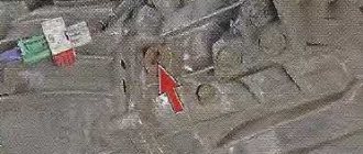
Where is
The location of the pump is a mystery to many; it is located in the engine oil sump, and in order to get to it you must drain the engine oil. The oil is drained into a clean canister and after the oil pump is replaced, it is refilled into the engine. Repair work to replace the oil pump is carried out on an inspection pit or lift, using a standard set of tools.
Operating principle and types of lubrication systems
All lubrication systems are divided into two main groups: with a “dry” and with a “wet” sump. The latter is more popular due to its ease of implementation. On the other hand, wet sump designs are prone to problems such as foaming and sloshing of the engine oil, leading to level fluctuations. In this case, its supply to the system may be unstable.
Dry and wet sump lubrication systems
A distinctive feature of “dry” systems is the presence of a separate tank in which engine oil is stored. After entering the engine, engine oil flows into the sump, but does not accumulate in it, but is pumped back into the tank by an additional pump. In this case, the crankcase always remains dry.
This design is more complex and expensive to manufacture, however, it allows the engine height to be reduced and provides reliable lubrication when the vehicle moves on inclined surfaces. This determined the scope of application of dry sump systems - mainly in off-road vehicles and special equipment.
In principle, oil can be supplied to the main engine components in three ways:
- Under pressure. Oil is forcedly supplied to all engine components using a pump.
- By splashing or gravity flow. The feed is carried out under the influence of the centrifugal force of the rotating parts of the engine. In this case, the oil is divided into small particles that look like oil mist. Thanks to this, the lubricant fills the entire space between the engine parts and settles on their surface.
- Partially under pressure and partially by gravity (combined method). In this case, oil is supplied to the most important components under pressure, and for the rest of the structure by splashing.
In the modern automotive industry, a combined method is almost always used, since it allows for more economical consumption of lubricants and at the same time guarantees timely lubrication of the main parts.
How does a combined wet sump lubrication system work?
The engine lubrication process is a repeating cycle. It consists of the following steps:
- When the engine starts, the oil pump is activated.
- The oil pick-up begins to suck oil from the oil pan, performing a rough cleaning.
- At the pump inlet, the oil passes through an oil filter, where fine cleaning is performed.
- From the pump, oil is supplied through lines to such engine components as crankshaft bearings (liners), camshaft supports, piston rings, as well as to the working surface of the cylinders. To do this, special nozzles can be installed in the system or holes can simply be made in the block.
- Excess oil supplied to the main components drains through special gaps onto the crank and gas distribution mechanisms. Their moving elements spray the working fluid, which ensures that it reaches the rest of the engine parts.
- The oil flows back into the oil pan, washing away metal shavings, carbon deposits and other contaminants from engine parts.
- After this, the cycle repeats.
Oil level and its meaning
Different types of engines require different amounts of oil in the system. In designs with a “wet” sump, the minimum and maximum values of the working fluid level are determined using a special dipstick, which is located on the cylinder block. It has two labels "min" and "max".
Checking the oil level in the system is performed with the engine turned off after it has been running for some time. In this case, it warms up sufficiently and flows into the pan. The dipstick is pulled out, wiped with a rag (rags) and immersed back into the pan. Next, take it out again and check the level. If the oil that gets onto the dipstick goes beyond the maximum or minimum value, topping up or draining the oil is necessary. This method also allows you to determine the condition and degree of contamination.
Differences between gasoline and diesel engine lubrication systems
There are no particular design differences in the lubrication systems of gasoline and diesel engines. However, since diesel engines operate at higher temperatures, the main difference is the engine oil used. The basic base of diesel oil is similar to that used in gasoline motor oils, but has a different additive package that allows it to provide the following functions:
- High cleaning ability - diesel engines are prone to excessive soot formation and therefore require intensive cleaning.
- Oxidation resistance - due to the high compression ratio, exhaust gases can penetrate into the diesel crankcase, which leads to oxidation of the engine oil and faster depletion of its service life.
Principle of operation
Since individual engine parts operate under different conditions, their lubrication should also be different. Oil is supplied to the most loaded parts under pressure, and to less loaded parts - by gravity or splashing. Systems in which parts are lubricated in different ways are called combined.
When the engine is running, the oil pump ensures continuous circulation of oil throughout the system. Under pressure, it enters the oil filter, and then to the main and connecting rod bearings of the crankshaft, piston pins, camshaft supports and cams, and the axis of the valve drive rocker arms. Depending on the design of the engine, oil is supplied under pressure to the turbocharger shaft, to the inner surface of the pistons for cooling, to the valve lifters and actuators of the phasing systems.
Oil reaches the cylinder surfaces by splashing through holes in the lower connecting rod head or nozzles in the lower part of the cylinder block. Getting on the cylinder walls, it reduces friction during piston movement and ensures freedom of movement of compression and oil scraper rings.
Drops of oil fall from pressure-lubricated parts into the sump. When they fall on the rotating parts of the crank mechanism, they splash, creating so-called oil mist in the crankcase. By settling on engine parts, it provides lubrication. The precipitated oil then drains into the oil pan and the cycle repeats.
Types of oil filters
Based on the principle of operation, the method of connection to the vehicle’s lubrication system and design features, several types of filters can be distinguished.
Full thread
A device of this type allows the full volume of motor fluid pumped by the pump to pass through. This operating mode is ensured by serial connection of the device to the engine lubrication system. The full-flow product is the simplest in terms of design, characterized by high cleaning speed. The downside is the relatively quick clogging of the material. In this case, a valve is activated that allows oil to pass through without filtering, but the engine does not lack lubricant (even if it is not purified), which is much better than its complete absence.
Partial flow
Products with this design work in parallel with the vehicle’s lubrication system. Not all the oil passes through such a product, but only part of it. This contributes to better purification of the motor fluid. However, the risk of pressure drop in the engine increases slightly in the event of critical and rapid filter contamination.
Combined
As the name implies, this device combines the “abilities” of the two products described above. Here, 90% of the oil is passed through a full-flow filter, and 10% through a partial-flow filter. This technology makes it possible to purify the oil almost 100%, which increases the service life of the power plant.
Oil centrifuge
This is a special type of filter used in trucks, tractors, and some types of construction and road equipment. Here, cleaning is carried out using centrifugal forces. The main structural elements are a rotor with an axis screwed into the bottom of the product. How does this type of oil filter work? The pump fills it under pressure, forcing motor fluid into the rotor through the axial holes. Then the oil “bursts” into the jets at high speed and rushes to the walls of the lid. As a result, due to the emergence of reactive force, the rotor begins to rotate, while all contaminants fall out as sediment at the bottom of the lid, and the oil filtered in this way enters the main line. Once upon a time, centrifuges were also installed on passenger vehicles.
Main oil line
Below the water jacket, along the right wall of the crankcase, there is the main oil line 11 (Fig. There are channels in the walls and bosses of the block to supply lubricant to the rubbing parts.
The upper section of the pump supplies oil through channels in the block to the main oil line, from where it passes to all rubbing surfaces. Unlike the ZIL-130 engine, the GAZ-53 engine oil from the lower section does not flow into the oil cooler, but into a centrifugal filter. Thus, the filter is connected in parallel and part of the oil passes through it, drained into the crankcase after cleaning.
| Diagram of a serial jet oil centrifuge KhTZ, connected to a branch of the main oil line and operating with a coarse filter. |
The RMC jet oil centrifuge of the D-54 tractor engine is connected to a branch of the main oil line.
The filter has a bypass valve that ensures oil flow into the main oil line, bypassing the filter, in case of significant contamination of the filter element, as well as in case of high oil viscosity during engine starting and warming up.
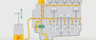
| Schematic diagram of the lubrication system. |
Oil pressure is controlled by electric pressure gauge 11, the sensor of which is installed in the main oil line, and the indicator is on the instrument panel. On some engines, to monitor the oil temperature, there is an electric thermometer 2, the sensor of which is mounted in the crankcase pan.
The connecting rod bearings and piston pin of compressor 6 receive lubricant from the main oil line 8 of the engine through a tube through the rear cover, seal and channels of the crankshaft and connecting rod of the compressor. After lubricating the compressor parts, the oil is drained into the engine crankcase through the chute of the compressor mounting bracket.
Oil pressure is controlled by electric pressure gauge 11, the sensor of which is installed in the main oil line, and the indicator is on the instrument panel. On some engines, to monitor the oil temperature, there is an electric thermometer 2, the sensor of which is mounted in the crankcase pan.
| Gear oil pump diagram. |
Oil pressure is controlled by electric pressure gauge 11, the sensor of which is installed in the main oil line, and the indicator is on the driver’s instrument panel. On some engines, an electric thermometer 2 is used to monitor the oil temperature, the sensor of which is located in the crankcase pan. Gear pumps are used in the lubrication system of automobile engines. The pump housing 5 (Fig. 12) contains the drive 7 and driven 2 gears. When the gears rotate, oil enters the suction cavity 6, fills the cavities between the teeth and is transferred in the cavities along the walls of the housing into the discharge cavity. Drive gear 7 is steel, mounted on a shaft, which is usually driven from the camshaft. Driven gear 2 rotates freely on the axle.
When centrally filling machines and mechanisms with lubricating oil, the valve pipe is connected to the main oil line.
The pressure in the lubrication system is limited by a pressure reducing valve located at the forward end of the main oil line. There is a hole in the valve through which oil is constantly supplied to the timing gears.
From channel 4 (Fig. 2.66, b), which connects the main oil line 2 with the main bearing, through hole 3, lubricant is supplied to the camshaft bushing 6. On the second journal, at the moment when the groove connects hole 3 with channel / (channel 6 in Fig. 2.66, a), oil flows to the channels in the head, and through them into the cavity of axis 4 (see Fig. 2.66, a) of the rocker arms and further - to the rocker arms and the upper tips of the rods.
The other, main part of the purified oil is sent through tube 13 to the main oil line.
Diesel oil system
The diesel oil system (Fig. 37) serves to create the necessary pressure and supply oil to the rubbing parts, remove heat from them, and also to remove wear products and carbon particles that fall between the rubbing surfaces. The oil system consists of two circuits: internal and external. The internal circuit of the diesel lubrication system is a collection of channels and tubes running through the parts. They provide oil supply to all parts of the parts, and the oil supply systems to the parts are fundamentally the same for all diesel engines. Then, after lubricating the parts, the pump takes oil from the internal circuit, for example, from the sump of a TsTs1M diesel engine, and supplies it through the oil drain pipe to the external circuit.
The external circuit, which ensures circulation, cleaning and cooling of the oil taken from the diesel sump and supplied to its oil manifold, includes pumps, oil coolers, filters, control and protective devices. Having passed the external circuit, the cooled and purified oil enters the diesel oil manifold, from which it again enters the internal circuit through the channels and is supplied to the main and connecting rod bearings of the crankshaft and then through the channels in the connecting rods - to cool the pistons and lubricate the rubbing parts of the cylinder-piston groups. To lubricate the camshaft bearings, oil from the manifold is supplied to the tubes. Oil is supplied to the pusher levers through tubes and then through channels in the pusher levers and rods to lubricate the timing mechanism levers. From the oil manifold, oil also flows to the camshaft drive gears and to the turbocharger bearings. After lubricating the diesel parts and assembly units, the oil is drained back into the diesel sump.
The oil reserve on the TEM2 diesel locomotive (378 l) is located in the system and in the oil sump of the diesel crankcase. Oil is poured through the neck of a centrifugal oil purifier. Oil circulation through a closed system is ensured by an oil pump, which takes oil from the oil sump and supplies it through pipe a to the upper manifold of the oil-air radiator sections 2 (Fig. 37). From the lower radiator manifold, the main part of the oil flows through pipe b into plate-slot filters (coarse cleaning), and from them into a pipe (oil manifold) running inside the crankcase. Part of the oil, approximately 15-20%, from radiator 2 enters filters with paper elements 7 (fine filter), from where it is drained through a pipe into the crankcase oil sump. Before starting the diesel engine, oil is taken from the crankcase by oil booster pump 10 and supplied through the discharge pipe d to the rubbing parts of the diesel engine. Non-return valve 8 does not allow oil to flow into pump 10 during diesel operation. Air is released through tap 9(7) when pumping oil before starting the diesel engine. Bypass valve 18 transfers oil from inlet pipe a to outlet b, bypassing sections 2 of the cooling device, if the difference between the pressures in these pipes is greater than 0.165 MPa. Such a pressure difference is possible when the viscosity of the oil increases, when the temperature drops or when sections of the cooling device are dirty. The unloading check valve 6 performs two functions: it passes a certain amount of oil through the filters 7 if its pressure is above 0.255 MPa, and it does not allow contaminated oil to drain from the filters into the crankcase after stopping the diesel engine. When the pressure in pipe b increases above 0.295 MPa, the oil is drained into the crankcase through control valve 17, bypassing all filters. Valve 5(3) is used when the oil is cold and should not be passed through sections of the cooling device.
To shut off the oil sections, valves 5(1) and 5(2) are installed on the pallets and discharge pipes. To bleed air from the sections of the cooling device of section 2, plug 3 is used. If necessary, oil from the crankcase is drained through a pipe on which valve 5(5) is installed. An additional plug is screwed onto the end of this pipe. The oil from the oil system is drained through valve 5(4). The pipelines running from the oil pump to the refrigerator sections and from the section to the slot-plate filters are connected by flexible hoses.
When repairing the oil system, oil leaks in pipeline connections are eliminated. Control valves are disassembled, unusable parts are replaced, and after assembly they are adjusted on a bench. Regardless of the condition, replace the hoses installed on the pipeline from the oil pump to the refrigerator section and from the refrigerator section to the plate filters.
Dry sump lubrication systems
In dry sump lubrication systems, the main supply of oil is contained in an independent oil tank, from where it is supplied to the main oil line of the engine by the pressure section of the oil pump. Such systems ensure an uninterrupted supply of oil to the rubbing parts of the engine on long steep climbs, descents and rolls without any oil starvation and oil leaks through the crankshaft oil seals. In addition, the use of a dry sump system makes it possible to reduce engine height, reduce oil consumption and maintain its physical and chemical properties for a longer period due to the ability to remove crankcase gases from the oil.
A typical diagram of a dry sump lubrication system for powerful diesel engines is shown in the figure. Before starting the engine, oil from oil tank 6 is supplied, bypassing all filters, to the main oil line of the engine using a pre-start oil pump with an electric drive, in order to reduce friction and wear of its parts during the initial start-up period.
In winter, the oil in the tank, the main oil supply line and pump 8 is preheated by a pre-starting liquid heater. Heating of the oil in the tank is usually carried out using a coil 7, in which the heated liquid of the engine cooling system circulates. When the engine is running, due to the operation of the pressure section 10 of the main oil pump, oil from the tank is supplied through the oil receiving strainer 9 to the full-flow coarse filter 3, and from there to the main oil line of the engine. Having lubricated the rubbing parts, the oil flows into the front and rear oil receivers of the engine, from where its main part (80...92%) is removed back into the tank using the pump-out section 11 of the main oil pump. This section consists of two pairs of gears - one for each oil receiver. On the way to the tank, the oil is cooled in the oil cooler 4. If the oil is still cold, and therefore has a high viscosity, then the bypass valve 5 is activated to protect the radiator from destruction. A small amount of oil (8 ... 20%) from the pumping section of the pump is supplied to the filter fine purification - oil centrifuge 1. The oil purified in the centrifuge flows into the engine crankcase. Some dry sump systems do not use a centrifuge. In such cases, a part-flow fine filter is located in the same housing with a belt slot coarse filter! The oil purified in the fine cleaning section flows into the engine crankcase.
A little about combined lubrication
The principle of operation is the continuous circulation of lubricating fluid inside the power unit. Just as in the human body the heart supplies blood to all organs, so the oil pump feeds first the large arteries, and then the thinner channels. Automobile pumps create a pressure from 2 to 20 atm.
The most common are gear devices. They rarely install adjustable plate ones. A pressure reducing valve is used to maintain pressure. Inside it there is a spring-loaded plunger, which, after a certain compression of the spring, communicates the pressure line with the crankcase. The oil after the pump passes through a filter, in which another bypass valve can be installed.
Next, the oil is sent: to the crankshaft support and connecting rod journals, to the camshaft supports and cams, to water the timing parts (pushers, rocker arms, valves). The operation of the combined system is accompanied by washing off the remains of unburned fuel and wear particles from the cylinder mirrors, which flow into the crankcase and deteriorate the quality of the working oil.
Types of lubrication systems
Despite the fact that all devices in the lubrication system perform the same functions, it can be of three types:
- oil spray system,
- pressure fluid supply system,
- combined system.
The first type has a fairly simple device: here the oil gets to the working parts thanks to special scoops installed on the crank heads of the connecting rods. The liquid captured from the pan is dispersed throughout the working area in the form of oil mist.
The disadvantage of this method of oil distribution is associated with uneven lubrication of structural elements due to periodic changes in its level in the lower engine container - the sump.
The volume of working fluid constantly changes with increasing crankshaft speed, tilting the vehicle and in aggressive driving mode. The scoops cannot control the amount of liquid splashing, so the motor periodically begins to experience oil starvation or, conversely, choke from an excessive amount of liquid.
The second type of system involves a continuous supply of engine oil to all elements of the installation. The lubricant composition is collected in the installation crankcase, and then supplied through special channels to the working unit. After completing the set goals, the oil flows into the oil pan.
Despite the fact that the system provides an economical and rational distribution of technical fluid, it has not received widespread use due to its cost and labor intensity.
Engine oil in the engine
By combining the technologies of spraying and supplying oil under pressure, engineers were able to create a combined type of lubricant distribution: protective fluid is supplied to the main structural components that are most susceptible to wear under pressure, while the rest of the mechanisms, operated in quieter conditions, are sprayed with oil by splashing.
The combined system involves the use of a wet and dry sump.
A wet sump means that it is constantly filled with working fluid.
The simplicity and reliability of the principle allowed it to become widespread: almost all cars are equipped with this system.
But it also has disadvantages: if air or a fuel mixture gets into the crankcase, the oil composition begins to foam and lose its lubricating properties. As a result, the internal combustion engine remains without the proper level of protection. To prevent this, it is necessary to regularly diagnose the system for depressurization.
A dry sump is ensured by the presence of a special tank in the power plant, into which all waste fluid flows. Here, mixing it with air and the fuel mixture is simply impossible. The advantages of such a system include the stability of its operation when the vehicle passes obstacles with a large angle of inclination. The dry sump principle is used on racing cars, sports cars and some SUVs.
As can be seen in the diagram: even when tilted, the liquid does not fall below the level of the intake tube.
Two Stage Oil Pumps
Let's consider the design of a two-stage oil pump using the example of a rotary-type unit from the VAG automaker.
- The first stage of operation is determined by the designers, based on the volume of oil required by the engine in all operating modes. From the injection cavity, oil is directed into the engine channels and to the movable rotor where it rests on the adjusting plate. In this mode, the volume of the suction cavity and, as a result, the amount of pumped oil is small.
- Second stage. As engine speed increases, the need for more lubricant arises. The pressure on the moving rotor weakens. Now the adjusting spring rotates the stator a few degrees, changing the position of the driven rotor. This increases the volume of the suction cavity and the amount of lubricant pumped.
In FSI Audi engines of 2.8 and 3.2 liters, the transition from the first to the second stage occurs at crankshaft speeds above 4600. Thanks to two-stage pumps, the designers managed to reduce fuel consumption by 1/3.
Engine lubrication system maintenance
The engine lubrication system, like other vehicle systems, certainly requires careful and timely maintenance, which determines the duration of the engine operation before major repairs. We are talking not only about monitoring the condition of the engine oil, but also all elements of the engine lubrication system as a whole.
The main thing in the maintenance of the engine lubrication system is to periodically check the engine oil level in the oil pan. This is done, as you know, using an oil dipstick. The normal oil level in the lubrication system should be between o and “MAX” on the dipstick. Trivial operation? Yes. But those who neglect it can have disastrous financial consequences. Lowering the level to the lower mark is unacceptable, as this leads to a drop in pressure in the oil supply lines, which, in turn, is fraught with increased wear, overheating, seizing or melting of the crankshaft liners.
You need to check the engine oil level in the engine lubrication system every 500 km and no earlier than 20-25 minutes after stopping the engine. First, the dipstick is removed, wiped with a dry cloth, inserted back into the hole until it stops, and removed again. A decrease in oil level as mileage increases is quite normal, because... it flows out, boils away and burns out. You just need to top it up periodically. Naturally, this primarily applies to cars with “experience”.
Mixing motor oils of different brands is not recommended. You need to add oil to the engine lubrication system using a funnel with a strainer, and not directly. However, the dipstick is useful not only from the point of view of level control
Along the way, you should pay attention to the color of the engine oil. If it begins to turn black faster than usual, then most likely the oil filter is clogged and the lubricant begins to flow uncleaned, which increases the wear rate of engine parts
You will have to change the oil, oil filter and flush the lubrication system.
It is also necessary to monitor the pressure in the engine lubrication system. For this purpose, most cars have a pressure sensor. The maximum pressure in the lubrication system is 2.5-3.5 atm. (it is limited by the oil pump pressure reducing valve). The minimum acceptable level is 0.5-0.8 atm. Finding the pressure gauge needle on the right side of the scale indicates (if, of course, the sensor and device are in order) that the pressure in the system is increasing. This can occur either due to the use of oil with a higher viscosity than necessary, or due to the pump pressure relief valve being stuck in the closed position. If the pressure gauge needle is in the extreme left position, it indicates a sharp drop in pressure in the line, which is much more dangerous, because At low pressure, the crankshaft liners operate in oil starvation mode and engine parts wear out faster.
The reasons for the drop in pressure in the engine lubrication system can be: low oil level, pump pressure relief valve jamming in the open position, wear of oil pump parts, increased gaps in which lubricant circulates, or engine oil leakage.
But the most dangerous thing for the engine is the abnormally low pressure drop in the lubrication system - 0.5 atm. and below. To monitor this situation, the car’s engine lubrication system has another control sensor that turns on a red warning light (usually this lamp is marked with the corresponding symbol - a watering can with a drop of oil) on the instrument panel in the car’s interior. Operating the engine with the emergency pressure lamp in the lubrication system constantly burning is not allowed. But on some engines this lamp may blink at idle speed (this should be indicated in the vehicle's operating instructions). However, if you increase the speed, the lamp should go out.
Source
Malfunctions of the engine starting system
Repair of the brake system KamAZ-5320
| page | 5/9 |
| date | 05.09.2019 |
| Size | 0.64 Mb. |
| File name | PZ.docx |
| Type | Essay |
5
| Malfunctions of the engine starting system The more complex the electrical circuit of the starting system, the more faults it may have. Frequent reasons for the failure of the starter are poor contacts of the wire tips at the battery terminals, the starter, connections to ground, a discharged or faulty battery. Signs of a malfunctioning engine starting system are very easy to diagnose.
In a faulty or severely discharged battery, the voltage drops sharply when the starter is turned on, so the traction relay or switch-on relay turns off the circuit. When the circuit is disconnected, the battery voltage rises and the relay closes the circuit again. Thus, the starter turns on and immediately turns off, so a repeated, frequent knock of the drive gear on the flywheel ring is heard. The starter does not turn on. The starter traction relay turns on, but the engine shaft does not rotate. Cause of the malfunction: severe burning of the contacts and the traction relay disk; poor contact between the brushes and the commutator. To check the starter motor, connect the terminals of the traction relay with a large cross-section conductor (10-15 mm2). If the armature rotates, you need to clean the contact bolts of the traction relay and the contact disk. Severely burnt contact bolts can be rotated 180° around their axis. If the starter motor armature does not rotate, you need to check the condition of the commutator, brushes and the tightness of the connection of the brush windings and ropes. The starter turns on, but the armature rotates at low speed or does not rotate at all. Causes of the malfunction: severe oxidation of the battery terminals or wire tips; poor tightening of wire ends; short circuit to the housing of the field winding or armature winding; thickening of the engine lubricant. The starter shaft rotates at high speed, but does not turn the engine crankshaft. The reasons may be slipping of the freewheel or breakage of the flywheel ring teeth. The starter does not turn off after starting the engine. The reasons may be sintering of the contacts of an additional relay or the switching disk with contact bolts. It is necessary to disconnect the battery terminal connected to ground and clean the contacts. Malfunctions of traction relays and switching relays The starter traction relay does not turn on; a clicking sound is heard from the switching relay contacts. Causes of the malfunction: severe oxidation or burning of the switching relay contacts; break in the wire connecting the switching relay to the terminal of the traction relay windings; break in the pull-in winding of the traction relay. Oxidized wire tips and battery terminals are cleaned, lubricated with technical petroleum jelly and tightened securely.
|
5
Possible problems
The most common problems encountered by motorists are failure of oil pump parts, filters (usually due to wear), loss of tightness of components, violation of adjustments or mechanical problems with pressure reducing valves.
Malfunctions of the engine lubrication system are usually associated with two groups of problems.
- Problems that lead to a decrease in oil pressure. They can be the result of deformation, wear, damage to the oil pump, low oil level, clogged filter, failure of the oil sensor, or sticking of the pressure relief valve.
- Problems that lead to increased oil consumption. This is the result of failure of the gas distribution mechanism, wear of the pump gasket, clogging of the crankcase ventilation, damage to the crank mechanism, weakening of the oil filter (or an initial error in securing it).
To identify pressure indicators, warning lights are used on the vehicle’s instrument panel. Low oil pressure is a direct signal indicating that the vehicle cannot be driven and requires repair or maintenance. To determine oil consumption, modern automatic cars have a special warning lamp on the instrument panel. To determine the problem in vehicles without such a lamp, a feeler gauge is traditionally used.
Wear and deformation
If diagnostics show that the parts are worn out, that is, they have served their service life, in most cases there is no point in trying to restore them. It needs to be changed. Gaskets, caps, and filter seals have a service life (indicated in the documentation for the parts), and if they are not replaced, the number of problems can only increase. For example, untimely replacement of the filter leads to a critical concentration of harmful impurities, which can lead to deformation of not only the filter itself, but also the housing. Deformation of the housing can be caused, for example, by wear on the outer surface of the pump bushings.
By the way, about deformation. It can occur much earlier than wear itself. But to solve the problem, you will have to not only change the deformed part, but also eliminate the cause that led to this trouble.
For example, with mechanical deformation, the root of the problem is often in malfunctions of other components interacting with the SSD. In particular, deformation of parts of the lubrication system may be a response to the failure of silent blocks or failure of the internal combustion engine. However, it is a comprehensive diagnosis that is important here. You shouldn’t immediately “blame” the engine mounting or silent blocks. For example, in a situation where timing valve parts are deformed, the quality of the oil is often to blame.