Alternator. For a VAZ or for a modification with a VAZ i injection engine, the electrical diagram will tell you which circuits should work at different key positions.
Limit switch for powering the engine compartment lamp.
And you will like it! 3. Charging system - 2
Should also be produced.
The information is intended for self-repair of cars.
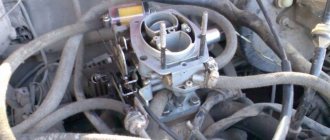
Carburetor valve control unit; VAZ color wiring diagram
If it is not there, then the coil is faulty and needs to be repaired or replaced.
It works, but when everything is hanging around like a spider web, it’s unpleasant and not practical. I think you will find it useful!
Automotive electronics course. Switch
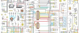
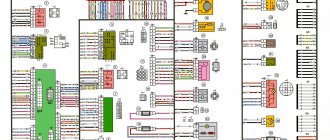
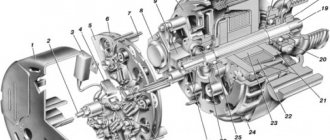
Wiring diagram for VAZ 2109
Many owners of the VAZ 2109 often need a complete electrical diagram and wiring diagram for the VAZ 2109 carburetor before their eyes. Here you can find a complete wiring diagram for the VAZ 2109 measuring 5000 by 2900 pixels, that is, it is huge.
Download diagram
Numerical designations on the diagram
| 1. Block headlight. | 2. Electric motors for headlight cleaners*. | 3. Lamp switch under the hood. |
| 4. Sound signal. | 5. Engine cooling fan electric motor. | 6. Fan motor activation sensor. |
| 7. Generator. | 8. Solenoid valve for turning on the headlight washers*. | 9. Rear window washer activation solenoid valve*. |
| 10. Windshield washer activation solenoid valve. | 11. Spark plug. | 12. Ignition distributor sensor. |
| 13. Ignition coil. | 14. Reversing light switch. | 15. Coolant temperature gauge sensor. |
| 16. Starter. | 17. Accumulator battery. | 18. Brake fluid level sensor. |
| 19. Switch. | 20. Top dead center sensor for cylinder 1. | 21. Diagnostic block. |
| 22. Carburetor solenoid valve control unit. | 23. Starter activation relay. | 24. Carburetor limit switch. |
| 25. Carburetor solenoid valve. | 26. Oil pressure warning light sensor. | 27. Window washer motor. |
| 28. Heater fan motor. | 29. Additional resistor for heater motor. | 30. Heater fan switch. |
| 31. Windshield wiper motor. | 32. Cigarette lighter. | 33. Heater lever illumination lamp. |
| 34. Plug socket for portable lamp. | 35. Engine compartment lamp. | 36. Glove box lighting lamp. |
| 37. Mounting block. | 38. Instrument lighting switch. | 39. Parking brake warning lamp switch. |
| 40. Brake light switch. | 41. Understeering's shifter. | 42. External lighting switch. |
| 43. Hazard switch. | 44. Rear fog light switch. | 45. Fog light circuit fuse. |
| 46. Heated rear window switch. | 47. Side direction indicators. | 48. Ceiling lamp. |
| 49. Connector for connecting to an individual lighting lamp. | 50. Light switches on the door pillars. | 51. Ignition relay. |
| 52. Ignition switch. | 53. Instrument cluster. | 54. Carburetor choke warning lamp switch. |
| 55. Rear lights. | 56. Level indicator and fuel reserve sensor. | 57. Rear window heating element. |
| 58. Rear window wiper motor. | 59. License plate lights. |
Numbering order of plugs in blocks:
- A – ignition switch;
- B – windshield wiper electric motor.
* – Installed on parts of manufactured vehicles.
We independently regulate the system
In order for the motor to operate normally, you need to set the angle. To complete this task, you will need to prepare tools, in particular, keys and screwdrivers. Before proceeding with the adjustment, you should start the internal combustion engine and let it run until it warms up. Please note that the idle speed should be at least 800 rpm.
After the internal combustion engine is warmed up, you need to open the hood and disconnect the silicone pipe, which produces vacuum from the fitting. One end of this pipe must be brought to your finger - if after this the pipe suctions, this indicates that there is a vacuum in the system. If this is the case, you will need to reduce the engine speed until the vacuum stops. Next, you will need to turn off the engine and bend the pipe until the clearance disappears. Using a wrench, you will need to loosen the fixing nuts that secure the distribution unit (the author of the video is the Engine Repair channel! And interesting!).
After the plug is removed and the inspection hatch is cleaned, you will see strips with which you can adjust the torque. The flywheel itself should be turned until it coincides with the elongated mark. These actions will allow you to optimally adjust the moment.
When everything is done, you will need a strobe or a simple light bulb with wires connected to it, the setup procedure is as follows:
- The red cable from the light bulb should be connected to the positive terminal on the coil under the hood.
- The black cable is the ground cable, which means it needs to be connected to the vehicle body.
- Start the engine and then rotate the switchgear housing. The strobe should send signals in time to the flywheel. The housing itself should be rotated until the mark is aligned with the mark on the flywheel.
Ignition circuit for VAZ 2109 carburetor
Is the ignition starting to fail? Then I recommend taking this diagram and, armed with a multimeter, ringing all the elements of the circuit.
Download diagram
Numerical designations on the ignition diagram
| 1. Accumulator battery. | 2. Generator. | 3. Ignition coil. |
| 4. Mounting block. | 5. Switch. | 6. Egnition lock. |
| 7. Distributor. | 8. Spark plug. |
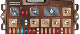
VAZ 2109 fuse diagram
Has the fuse blown again? Because you loaded your VAZ 2109 with a powerful light or installed a sub for which the wiring and fuse box were not designed? Then this fuse diagram will come in handy!
| № | Ampere | Purpose |
| 1 | 8 | Right fog lamp |
| 2 | 8 | Left fog lamp |
| 3 | 8 | Headlight cleaners (at the moment of switching on) Headlight cleaner switching relay (contacts) Headlight washer switching valve |
| 4 | 16 | Headlight wiper motor Headlight wiper relay (winding) Heater motor Window washer motor Rear window wiper motor Rear window washer timing relay Windshield and rear window washer activation valve Cooling system electric fan relay relay coil Coil of the rear window heating relay coil Rear window heating control lamp Wardrobe lighting lamp box |
| 5 | 8 | Turn indicators in turn signal mode and the corresponding indicator lamp Rear lights (reversing lamps) Indicator lamp for fuel reserve, oil pressure, parking brake, brake fluid level, carburetor choke Voltmeter and indicator lamp for charging the battery Gearmotor and windshield wiper switch relay Generator excitation winding (at start-up) “STOP” indicator lamp Coolant temperature and fuel level indicators |
| 6 | 8 | Rear lights (brake lights) Body interior light Power windows and power window relay |
| 7 | 8 | License plate lights Engine compartment lamp Indicator lamp for turning on side lighting Instrument lighting lamp and cigarette lighter lamp Heater lever illumination panel |
| 8 | 16 | Engine cooling fan electric motor and its activation relay (contacts) Sound signal and its activation relay |
| 9 | 8 | Left headlight (side light) Left rear light (side light) |
| 10 | 8 | Right headlight (side light) Right rear light (side light) |
| 11 | 8 | Direction indicators and hazard warning relay (in hazard mode) Hazard warning lamp |
| 12 | 16 | Heated rear window element and heating relay Cigarette lighter Socket for portable lamp |
| 13 | 8 | Right headlight (high beam) |
| 14 | 8 | Left headlight (high beam) High beam indicator lamp |
| 15 | 8 | Left headlight (low beam) |
| 16 | 8 | Right headlight (low beam) |
| Relay | ||
| K1 | Rear window washer time relay (451.3747 / 2108-3747110, 2108-3747110-06) | |
| K2 | Relay-breaker for direction indicators and hazard warning lights (493.3747 / 2108-3747010-02) | |
| K3 | Windshield wiper relay breaker (522.3747 / 2108-3747710) | |
| K4 | Contact jumpers in place of the lamp integrity monitoring relay. Lamp integrity monitoring relay (4402.3747 / 21083-3747410, 21083-3747410-06) | |
| K5 | Headlight high beam relay (113.3747 / 2105-3747210-10, 2105-3747210-12) | |
| K6 | Headlight cleaner relay (112.3747 / 2105-3747210, 2105-3747210-02) | |
| K7 | Power window relay (13.3747 / 2105-3747210-10, 2105-3747210-12) | |
| K8 | Relay for turning on sound signals (13.3747 / 2105-3747210-10, 2105-3747210-12) | |
| K9 | Relay for turning on the electric cooling fan (13.3747 / 2105-3747210-10, 2105-3747210-12) | |
| K10 | Relay for turning on the heated rear window (13.3747 / 2105-3747210-10, 2105-3747210-12) | |
| K11 | Relay for low beam headlights (13.3747 / 2105-3747210-10, 2105-3747210-12) | |
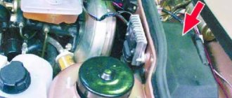
What's under the hood
Let's remember how the new power unit differs:
- The distributor and ignition coil, responsible for the formation of a spark in the cylinders, have been replaced by an electronic unit - an ECU;
- The VAZ 2109 engine compartment wiring to the injector has a number of design features. In particular: more connectors, other parameters (cross section, insulation);
- Instead of a carburetor, a block of electronically controlled injectors is installed;
- Automation is based on the readings of many sensors that are not on carburetor engines, which means that the wiring for the VAZ 2109 injector has more components.
There are more wires and electronics under the hood of the injection version of the VAZ 2109
For reference: In injection versions, a single ignition module is installed under the hood, in which the coil and switch are combined into a common spark-forming device.
Let’s also look at modifications to the electrical wiring on KamAZ.
Control sensors
In order for a power unit with an injection system to work, the electronic unit needs readings of the most important parameters.
And special sensors that the motor is equipped with are responsible for this:
- DPKV (crankshaft position sensor). One of the most important parameters, without which the car will not even start. It tells the ECU when it is necessary to inject fuel and ignite it in the cylinder;
- MAF (mass air flow sensor). Installed after the air filter and is responsible for the quantitative composition of the air-fuel mixture;
- DD (knock sensor). Using its readings, the ECU calculates the ignition timing - the most important parameter for the beginning of the ignition phase of the air-fuel mixture in the car cylinder;
- TPS (throttle position sensor). Unlike a carburetor circuit, where the pedal directly controls the damper, in injection engines the pedal is not connected to the actuator;
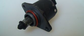
- IAC (idle air control). Necessary for enriching the air-fuel mixture for stable engine operation when not in motion;
- DT (temperature sensor). Available on all engines and is responsible for controlling the coolant temperature;
- DSA (vehicle speed sensor). Based on its readings, the ECU calculates the amount of fuel and air.
The presence of sensors also modified the electrical circuit of the car - the VAZ 2109 electrical wiring to the injector has many connectors for connecting sensors to the ECU.
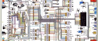
Original wiring diagram for VAZ 2109 injector
In the photo above, the diagrams with sensors are indicated by numbers:
- TPDZ;
- DPKV;
- DT;
- DSA;
- Canister purge valve;
- DMRV;
- DD and others.
Tip: To install them in an old car body, you do not need to modify anything. The manufacturer has minimized preparatory work, and the instructions supplied with the power unit describe in detail the procedure for installing attachments.
ECU block
The electronic “brains” of a modern injection engine are the ECU unit.
It is he who is in charge of all the electrical processes of the power unit, and structurally consists of:
- read-only memory (ROM);
- random access memory (RAM);
- a microprocessor that processes electronic signals coming from engine sensors.
The cost of an error when interfering with the operation of the ECU can be prohibitively high
Advice: it is unacceptable to interfere with its work, as well as to diagnose its operation parameters with your own hands.
All electronic components of the ECU are designed for very low voltage. Even an electrostatic discharge from touching it with your hand can damage them.
To avoid damage to the computer, technicians at service stations:
- avoid touching the ECU plugs;
- do not touch electronic components on its boards with their hands;
- when flashing ROM settings, the pins of the microcircuit are isolated.
Wiring - VAZ 2109: consider the “filling of the pie”. Read about it here.
Wiring diagram for power windows on a VAZ 2109
Tired of lifting windows with ordinary “oars”? Then install electric windows using the wiring diagram for electric windows on a VAZ 2109.
Download diagram
Numerical designations on the diagram
| 1. Mounting block. | 2. Ignition relay. | 3. Egnition lock. |
| 4. Right door electric window motor. | 5. Left door electric window motor. | 6. Right door power window switch. |
| 7. Left door power window switch. | K7. Power window power relay. | A. To terminal “30” of the generator. |
| B. To the wiring harness block connected to the heater lever illumination display. | ||
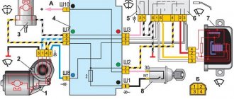
VAZ 2109 generator circuit
If you lose charge, this is most often due to a failure of the generator, and most often it is the generator brushes, but it happens that there are winding breaks and a short circuit in the circuit or an open circuit. In this case, I recommend that you familiarize yourself with this generator circuit for the VAZ 2109.
Download diagram
Numerical designations on the diagram
| 1. Generator. | 2. Negative valve. | 3. Additional diode. |
| 4. Positive valve. | 5. Battery discharge warning lamp. | 6. Instrument cluster. |
| 7. Voltmeter. | 8. Mounting block. | 9. Additional resistors of 100 Ohm, 2 W. |
| 10. Ignition relay. | 11. Ignition switch. | 12. Accumulator battery. |
| 13. Capacitor. | 14. Rotor winding. | 15. Voltage regulator. |
Additional tips from the professionals
By taking into account some tips and tricks provided by professionals, you can independently extend the life of your car wiring:
- car owners must periodically inspect the external condition of the insulation and all connectors by looking under the hood of their car;
- If a minor defect is discovered during inspection, the damaged wire must be replaced to prevent a short circuit. If the break is insignificant, then you can wrap it with high-quality electrical tape for a while, but it is not recommended to postpone replacement for a long time;
- A special product, WD-40, which can be purchased at an affordable price in a specialized store, will help remove the oxidizing layer from the surface of the connector;
- It is advisable to make additional protection for the engine crankcase to prevent moisture from getting on the wires.
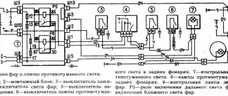
Turn signal diagram for VAZ 2109
Don't they blink? Then go through the circuit with a multimeter and find out the cause of the turn signal malfunction.
Download diagram
Numerical designations on the turn signal diagram
| 1. Block headlight. | 2. Turn signal repeaters. | 3. Fuse mounting block. |
| 4. Ignition relay. | 5. Egnition lock. | 6. Indicator lamps on the instrument cluster. |
| 7. Rear lights. | 8. Hazard switch. | 9. Turn signal switch. |
| K2. Relay for direction indicators and hazard warning lights. | ||