Good day to all! Today I’ll tell you how to check a Hall sensor, what methods exist for assessing the condition of a device, and what you should pay attention to.
Motorists and those who ride a scooter and have a contactless ignition system or electronic ignition in their vehicle design have probably heard about this sensor or controller. It is also often called the camshaft position sensor or simply the camshaft position sensor.
The device is even found on phones. But since we have an automotive website, we will talk about the Hall sensor specifically in relation to cars and vehicles.
Before touching on the topic of verification methods, it would not be amiss to understand the very essence of the device in question, its functions and operating principle.
Hall sensor and other reasons: no spark on Audi 80 b4?
Updated: 2016-11-27 Author: audi39 Number of comments: 0
When faced with a lack of spark in an Audi 80 b4, car owners cannot always determine the cause of this problem immediately. When the engine begins to malfunction, power is lost, fuel consumption changes: in these cases, it is necessary to test the spark plugs.
Checking spark plugs on an Audi 80 can be done in the following ways:
- Checking for spark. After unscrewing the spark plug, you need to put a high-voltage wire on it and lean it against the engine. Checking for a spark occurs when the starter turns over.
- Using a multimeter. This method will only help determine the serviceability of the wires. The point is to measure resistance. If the indicator is below an acceptable value, the wire is faulty and needs to be replaced.
- With a special test gun. This device looks like a test bench for testing spark plugs under pressure. To check, you need to insert the part into the seat and cover it with a lid. Next, click on the button. If the indicator light on the device signals and a spark appears on the electrode, we can conclude that the spark plug is in good condition.
- Using a piezoelectric element. This mechanism can be made independently using a piezo module from a lighter. We press this device to the spark plug, and screw the running wire to its tip. We press the button. If the spark does not pass, replace the spark plug.
- Remove the wires one by one. This method involves disconnecting the wires going from the spark plug to the breaker-distributor one by one. Before removing the armor wire, you need to listen to the sound of the engine and remember it. After disconnecting the wire from the spark plug, listen to the sound of the engine again. We compare the first and second, if the sound has not changed, then a faulty spark plug has been found.
The principle of operation of the electric ignition system of the Audi 80 b4
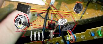
A Hall sensor is installed under the distributor, to which the voltage goes. This sensor acts as a control wire that gives an impulse to the ECU. From the electronic control unit, adjustments and the required delays are sent, using data read from other engine sensors, to the switch, which is located next to the ignition coil. The switch acts as a transistor. When voltage is applied to the switch, the chain closes or opens, as a result, voltage is supplied to the coil and a spark is formed.
Each operation must be carried out with the ignition on. Measurements are taken with a multimeter.
Checking the serviceability of the ignition coil
The first thing you need to check is the coil. It fails very rarely, but it is necessary to test it to rule out possible causes. In addition, it is not difficult to check; we immediately test the main winding, then the secondary one. On the top of the coil are the standard pin designations.
On the multimeter, select the lowest resistance reading. We measure the main winding, lean the tester terminals against the elements of the coil with external threads. The values should be within 1 - 1.5 Ohms.
The next measurement is carried out on the resistance in the secondary electrical winding. In this case, we will apply the probes to the external thread and the element that is located in the center of the coil cover. The measurements should be within 7 kOhm.
Are all values confirmed? This means the coil is normal. Let's move on to the next verification step. The values vary - replace the coil.
Examining the Switch
This device breaks down quite often. Therefore, it is necessary to test both the switch itself and its management. First of all, you need to remove the cover and measure the presence of voltage passing through it. You need to measure with the lid removed.
We lean the probes against the outer legs. The value should be close to the battery voltage, i.e. about 12 V. If there is no voltage, the most likely problem will be in the contacted ignition switch block or in the wiring that is connected to it.
Next, we check the passage of voltage through the ECU switch. With the cover removed, we lean the multimeter probes against the two outer legs and turn the starter. During these actions, voltage should appear on the device.
If voltage is present, then we further test the switch itself. It is necessary to put a cover on it, remove the rubber band for sealing and using a simple wire with the ignition on, we supply 12V from the battery to the second terminal. At the same time, the high voltage electrical wire from the coil must be applied with the other edge to any area of the body. At the hour at which voltage is applied, a spark is forced to appear. So we improvise the process of the ECU signal and the operation of the Hall device, and then straight away, throwing everything away, the control voltage arrives.
If there is no spark, it is necessary to replace the switch with a working one.
Hall sensor malfunctions
Let's move on. When there was no voltage at the second terminal, and the serviceability of the switch was checked, we came to the logical conclusion that the problem could be as follows:
- Hall sensor problem
- Problem with the electronic control unit
- There is a problem with the wiring that connects the Hall - the electronic control unit - the switch.
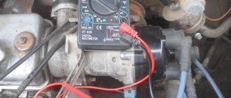
Let's start off easy. Let's see if voltage is supplied to the Hall sensor. To do this, remove the cover and start the ignition. Next, we measure the voltage by connecting the multimeter probes to the side terminals of the sensor. The device should show 10-11 V. If everything is normal, move on.
The next step will be to inspect the connected wiring Hall - electronic control unit - switch. You will need to remove the cover from the sensor and supply voltage to the second terminal from the battery with a spare wire. In the meantime, we lean the wire from the ignition coil with the other edge against a section of the body. When voltage is applied, the Hall sensor is improvised and a spark should appear. The presence of a spark indicates that the electronic control unit and wiring are in good condition. And most likely the problem lies in the Hall sensor itself.
Testing the sensor. The cover is inserted into the connector itself, remove the insulation from it and install the multimeter probes to the second and third legs of the cover. We rotate the starter, but it is not always possible to correctly determine the impulse. It is easier to install the head on the crankshaft pulley and slowly rotate the engine. The voltage on the multimeter is forced to change to 0 and 5-7 V. If this does not happen, then the problem is in the sensor and it needs to be replaced.
Causes of failure in the video:
Step-by-step instructions for replacing the Hall sensor on an Audi 80 with your own hands
- Before removing the distributor, set the ignition to the marks! Next, we remove the distributor - unscrew the bolt at “13” that secures the distributor - take out the bolt - remove the bracket on top which actually presses the distributor - then twist it in one direction - then in the other and carefully pull it out towards you .. - if it doesn’t work... twist it from side to side - without fanaticism - it is better to twist the slider - because it doesn't come out from behind the gear! When the distributor starts to come out, be CAREFUL that dirt does not get into the engine compartment - otherwise goodbye oil filter!
- The sensor was used from the 8th model Lada (suitable for 8, 9, 10) they are all the same, BUT ATTENTION! We buy a sensor with a half-iron body - it’s the only one that will fit - don’t buy a completely plastic one - look for one exactly like the one in the photo.
- So we removed the distributor - we look down at the gear - it is attached to the distributor shaft by means of a key - which must be knocked out - at first it will be difficult - then it will be easier when we put it back - note that the riveted place of the key should fit into the groove - The groove for The keys are only on one side of the gear! As soon as you knock it out, pull out the shaft - and you will immediately see 4 self-tapping screws, which also need to be unscrewed - to remove the pad from the hall sensors!
- Take a file - grind a small corner under the sensor on the body itself as shown in the figure - without fanaticism - just so that the sensor fits - and don’t cut through - otherwise the bushing inside which the shaft rolls will have a play and throw away the distributor!
- Next, we solder the plug to the sensor - I ran the wires from the bottom of the bar - there is a lot of space left in the case, so this was removed, but anyone can do it as it is convenient - I think everyone will figure out this moment - what length to leave and how to lay them correctly - so as not to pinch and so that the curtain they were not cut off)))
- Next, we sharpen the hall sensor housing with a file without fanaticism - so that it fits into the distributor housing in its original place!
- We rivet the sensor, cut to size - and tested approximately on the spot - into its standard place and this is the picture you should have.
- as you can further notice, the shutter on the shaft will touch the sensor - and you won’t completely insert the shaft into place - the sensor will not allow you to do this - after all, you have filed off part of the round surface - against which the head of the shaft with the shutter rubs, and the sensor itself is higher standard - but don’t be sad... all you need to do is find a washer 2 millimeters high - the inner hole seems to be 12.5 - the outer 23 or 24 - measure it yourself... because... At first I got 11.5 and 23...and then I had to adjust it with a file so that the washer would fit
- Next, we put the original ring at the very top - then the 2 mm washer that we made - and try to turn it manually - everything... doesn’t touch it and everything sits as it should? well great! We take a syringe 2 cube with a needle or whatever you have - lubricate the shaft generously with engine oil - a new washer so that it gets used, put everything together carefully - hammer the key back on the sprocket - then we put the slider 1.5-2 cm later on the distributor (since . gear with a bias - when landing, the slider should be exactly on the mark - if you place the distributor with the slider exactly on the mark - when landing in the saddle, the slider will fly off to ignition very early - you will have to remove the timing belt and install everything again - do you need it?) Next, tighten the bolt to 13 with the bracket set at 8 mm approximately earlier - because Your piston is not the freshest - and the car will pull better with the ignition a little earlier - turn the key.
How to easily check the Hall sensor yourself: tools and instructions
Good day to all! Today I’ll tell you how to check a Hall sensor, what methods exist for assessing the condition of a device, and what you should pay attention to.
Motorists and those who ride a scooter and have a contactless ignition system or electronic ignition in their vehicle design have probably heard about this sensor or controller. It is also often called the camshaft position sensor or simply the camshaft position sensor.
The device is even found on phones. But since we have an automotive website, we will talk about the Hall sensor specifically in relation to cars and vehicles.
Before touching on the topic of verification methods, it would not be amiss to understand the very essence of the device in question, its functions and operating principle.
What it is
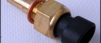
A Hall sensor is a controller that is located in the distributor and is one of its key components. The distributor, in turn, is a breaker-distributor.
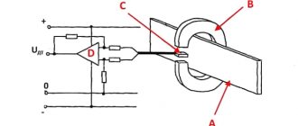
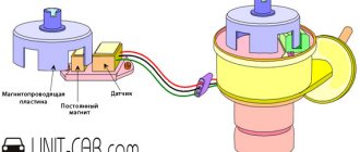
The Hall sensor (HL) is located directly near the distributor shaft, where a special magnetically conductive plate is attached. Outwardly, it resembles a crown. This plate has exactly the same number of slots as the number of cylinders in a particular power plant. Therefore, if you have a car with 6 cylinders, then there will be exactly 6 slots. A permanent magnet is installed directly inside the controller.
Now regarding the principle of operation. If you understand this issue a little, you won’t see anything complicated here.
When the shaft rotates, the metal blades pass alternately through the slots in the controller in question, that is, in the DC. As a result of rotation, a pulse voltage is generated.
This voltage, due to the presence of a switch, goes directly to the ignition system coil. This is where the conversion process to high voltage takes place. As a result, it ends up on the spark plugs. The design of the DC provides for the use of 3 different terminals at once. The first serves to connect to ground, and the second receives a plus, receiving a voltage with a nominal value of about 6 V. There is also a third terminal from which the pulse signal goes to the switch after conversion.
Verification methods
You can use several diagnostic methods for the sensor located on the distributor.
Depending on the available means and capabilities, the motorist can check the current condition of the Hall controller with his own hands, evaluate its performance and make the appropriate decision on replacement.
As soon as you notice one or more of the symptoms presented, you should get checked. You can do it in several ways. I propose to consider them separately.
Wedge with wedge
The simplest and most effective method that does not require you to equip yourself with a tester or multimeter. But you will need a known-good similar Hall sensor.
The essence of diagnosis is outrageously simple. You remove the old controller and install a new one in its place. If after the manipulation the symptoms go away and engine operation returns to normal, then simply leave the new part in place. If you borrowed a DH from a friend or neighbor in the garage, remove the device, say thank you, and go to the auto parts store.
Voltmeter and multimeter
Using a voltmeter or a classic tester, you can easily check the condition of the device.
I think every motorist can use the tester. The task is to measure the voltage at the sensor output.
If the DC is in good condition, the tester will produce values in the range of 0.4-11 V.
A universal multimeter is used in exactly the same way. You just need to select the voltmeter mode on it.
Sensor simulation
Quite an interesting and effective method. But here you will have to do a little work with your own hands.
The principle of imitation is as follows. First, remove the block from the DH, which has 3 plugs. Next, start the ignition on the car, then connect outputs 3 and 6 to each other.
If a spark appears during such manipulation, then most likely the DC has failed.
Without testers
When testers are not available, testing can be done using a slightly different method.
Here you need to carry out step-by-step manipulations:
- the spark plug is connected to the wire terminal from the coil;
- the threaded part of the spark plug is connected to the ground;
- the carriage with the sensor is dismantled;
- connector is connected;
- the ignition is turned on;
- a metal object is held near the sensor;
- When a spark appears on the spark plug, the DH is operational.
Just be extremely careful when doing such manipulations with your own hands.
Homemade tester
You can assemble an analogue of the tester from practically available materials.
The testing device consists of a regular LED, a 1 ohm resistance and two pieces of flexible wiring that need to be soldered to the leg.
Wires are connected to terminals 1 and 3 of the DC plug box. If the polarity is correctly selected, the LED should light up. If not, try swapping. Now you need to do the following:
- the first wire on the first terminal remains in place;
- the wire from the third terminal is connected to the second terminal;
- the camshaft turns (using a starter or manually);
- The behavior of the diode is monitored.
If the diode starts blinking, then everything is fine with the ignition sensor, and there is no need to change it.
There are really quite a lot of verification methods. Choose according to your taste.
Have you ever had to check a Hall sensor? What diagnostic methods did you use and what was the result?
Subscribe, leave comments, ask questions and don’t forget to tell your friends about us!
Examination
The health of the Hall sensor can be checked in the following ways:
- By installing a known-good sensor in place of the one being tested. If the problems disappear when you start the engine, then the “original” sensor is faulty and needs to be repaired or replaced.
- Measurement of the sensor output voltage with a tester. A working device will show voltages ranging from 0.4 to 11 V.
- By creating an imitation of the sensor by removing the three-pin block from the distributor, connecting wires 3 and 6 of the switch output and turning on the ignition. A spark that appears indicates a breakdown of the sensor.
Self-repair of distributor (Hall sensor)
The information is applicable to repairing many vehicles.
The idea is not new, and not mine, but I decided to show it in pictures. It happens that the Hall Sensor stops working normally - then the car may either not start at all, or it starts according to the mood and works at random intermittently (that is, there is a spark, then there is no). It can be repaired very cheaply (a chip costs less than $1).
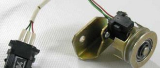
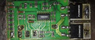
Removed sensor from Audi 2.0 5-cylinder engines. 2.3 (this particular sensor from Audi 100 C4, AAR engine) looks like this:
To check it, you need to connect the +12 battery to the red wire, “-“ to the brown wire, and between green and red - a multimeter in direct voltage (DC) measurement mode (or an LED that will light up and go out). In this case, the multimeter will show about 12V, and when the gap between the magnet and the sensor is blocked with a metal plate - 0V. Moreover, even if you tap on the sensor, everything should work stably. Faulty ones will either not work at all, or depend on a blow to them and turn on every other time. A faulty sensor must be replaced.
You can buy a new sensor assembly that will fit perfectly Huco 13 8156
- but its price tag is higher than the price of a new assembled distributor (Chinese
Patron P41-0002
) - and this will not make you very happy. We need a cheap solution and we have it.