The 10th generation Mitsubishi Lancer was produced in 2007, 2008, 2009, 2010, 2011, 2012, 2013, 2014, 2015, 2016, 2017 with engines of 1.5 1.6 1.8 2.0 liters. During this time, the model underwent restyling. Mitsubishi Lancer Evolution
or
Mitsubishi Lancer Evo
is a sporty version of the Lancer lineup.
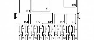
In this article we will show a description of the fuses and relays of the Mitsubishi Lancer 10 with block diagrams, photos - examples of execution and their locations. Note the fuse responsible for the cigarette lighter.
The number of elements in the blocks of your Mitsubishi Lancer 10 may differ from those presented and depends on the year of manufacture, level of equipment and region of delivery.
Fuses and relays Mitsubishi Lancer X (Lancer10) in the engine compartment
In the engine compartment
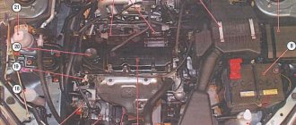
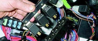
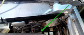
Let's start with the engine compartment. The block itself is located on the right side if you open the hood and look under it or on the left side in the direction of travel. Open the lid, there is nothing complicated here. There is one latch. And we see something like the following.
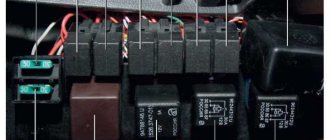
There are both relays and fuses here. Some of the fuses are located outside the unit, on the power wires.
34, 35, 37 at 80 A and fuses 36, 33 at 120 A. Fuses provide power to several circuits at once. hence such high rated currents.
Below is the purpose of these fuses and their ratings for the engine compartment.
| № | Purpose | Rated current | |
| 1 | Fog lights | 15 A | |
| 2 | Engine | 7.5 A | |
| 3 | Automatic transmission | 20 A | |
| 4 | Sound signal | 10 A | |
| 5 | Generator | 7.5 A | |
| 6 | Headlight washers | 20 A | |
| 7 | Air conditioner | 10 A | |
| 8 | Throttle body/oil cooler fan (Twin Clutch SST) | 15 A | |
| 9 | Anti-theft alarm sound | 20 A | |
| 10 | Wiper blade heater | 15 A | |
| 11 | — | — | |
| 12 | Power tailgate | 30 A | |
| 13 | Outdoor lighting system during daytime | 10 A | |
| 14 | High beam headlight (left) | 10 A | |
| 15 | High beam headlight (right) | 10 A | |
| 16 | Low beam headlight (left) with gas discharge lamp | 20 A | |
| 17 | Low beam headlight (right) | With gas discharge lamp | 20 A |
| 18 | Low beam headlight (left) | With halogen lamp | 10 A |
| 19 | Low beam headlight (right) | With halogen lamp | 10 A |
| 20 | Power circuit engine electrical equipment | 10 A | |
| 21 | Ignition coil | 10 A | |
| 22 | Power circuit engine electrical equipment | 20 A | |
| Fuel line heater | 25 A | ||
| 23 | Fuel pump | 15 A | |
| 24 | Starter | 30 A* | |
| 25 | — | — | |
| 26 | Anti-lock braking system | 40 A* | |
| 27 | Anti-lock braking system | 30 A* | |
| 28 | Condenser fan motor | 30 A* | |
| 29 | Engine cooling fan motor | 40 A* | |
| 30 | I/O device | 30 A | |
| 31 | Audio amplifier | 30 A | |
| 32 | Electrical equipment of a diesel engine | 30 A | |
| 33 | Spare fuse | 10 A | |
| 34 | Spare fuse | 15 A | |
| 35 | Spare fuse | 20 A |
Relay
| 1 | A | Fog light relay |
| 2 | B | Horn relay |
| 3 | C | Compressor clutch relay |
| 4 | D | Add. equipment |
| 5 | E | Auto relay gearboxes |
| 6 | F | Add. equipment |
| 7 | G | High beam relay |
| 8 | H | Throttle relay |
| 9 | I | Add. equipment |
| 10 | J | Outdoor lighting relay during daytime |
| 11 | K | Fuel pump relay |
| 12 | L | Add. equipment |
| 13 | M | Fan relay |
| 14 | N | Starter relay |
| 15 | O | Low beam relay |
| 16 | P | Cooling system relay |
| 17 | R | Add. equipment |
| 18 | S | Engine control relay |
| 19 | T | Add. equipment |
| 20 | Q | A/C Fan Relay |
Now let's go to the salon.
In the cabin
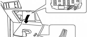
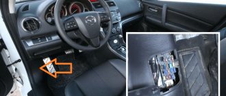
In it, on the left side below the steering wheel there is a plastic door, a plug. * - there may be a different type of door.
We open it and see the following.
Fuses in the cabin
| № | Power circuit | Rated current, A |
| 1 | Heater (stove) | 30 A |
| 2 | Brake lights (brake lamps) | 15 A |
| 3 | Rear fog light | 10 A |
| 4 | Windshield wiper | 30 A |
| 5 | Accessory circuits | 10 A |
| 6 | Electric door locks | 20 A |
| 7 | Audio system | 15 A |
| 8 | Control unit relay | 7.5 A |
| 9 | Interior lighting lamps (plafonds) | 15 A |
| 10 | Hazard warning lights | 15 A |
| 11 | Rear window wiper | 15 A |
| 12 | Instrumentation | 7.5 A |
| 13 | Cigarette lighter fuse/power socket Mitsubishi Lancer X. | 15 A |
| 14 | Egnition lock | 10 A |
| 15 | A roof with a panoramic view | 20 A |
| 16 | Exterior mirrors | 10 A |
| 17 | All-wheel drive system | 10 A |
| 18 | Reversing lights | 7.5 A |
| 19 | Power outlet | 15 A |
| 20 | Electric windows | 30 A* |
| 21 | Rear window defroster | 30 A* |
| 22 | Heated exterior mirrors | 7.5 A |
| 23 | AC power supply | 15 A |
| 24 | Electric seats | 25(20)A |
| 25 | Seat heating | 30 A |
Relay in the cabin
As you can see, there is a relay in the block. Their purpose is as follows.
| 1 | A | Add. equipment |
| 2 | B | Electric Fan Relay |
| 3 | C | Seat heating relay |
| 4 | D | Heated rear window relay |
The fuses and blocks themselves are identical to the ASX, from about the same years. I also already talked about ASX fuses and relays.
Fuses on Mitsubishi Lancer 10: where are they, diagram | uazlyuks.ru
Fuses and fuses in Mitsubishi 1 (from 2008) are located in three zones:
- under the dash,
- in the engine compartment,
- to battery + terminal.
The covers have pictograms and fuse labels. They can be done in different languages.
Replacement of faulty fuses is carried out using special tweezers.
Cabin fuses
They are located under the decorative cover on the dashboard. It can be easily removed without special tools.
Fig.1
Fig.2
Access to the fuses is normal.
Explanation for Figure 2
Purpose Item number Denomination
| Stove engine | 1 | 30A |
| Feet | 2 | 15A |
| Rear fog lights | 3 | 10A |
| Wipers | 4 | 30A |
| Additional devices | 5 | 10A |
| Central lock | 6 | 20A |
| Radio tape recorder | 7 | 15A |
| ECU main relay | 8 | 7.5A |
| Interior lighting | 9 | 15A |
| Emergency crew | 10 | 15A |
| Rear wipers | 11 | 15A |
| Dashboard | 12 | 7.5A |
| Cigarette lighter, additional socket | 13 | 15A |
| Start key | 14 | 10A |
| Power sunroof | 15 | 20A |
| Mirrors | 16 | 10A |
| Differential lock | 17 | 10A |
| Reversing light | 18 | 7.5A |
| Additional connector | 19 | 15A |
| Glass control | 20 | 30A |
| Heated rear window | 21 | 30A |
| Heated mirrors | 22 | 7.5A |
| Additional power (antenna amplifier) | 23 | 15A |
| Seat drive | 24 | 25A |
| Heated seats | 25 | 30A |
Fuses under the hood
The location of the block is shown in Figure 3 (position 11).
The appearance and dismantling of the cover is shown in Figure 4.
A photograph of the arrangement of elements is shown in Figure 5
Photo of the battery block
Purpose Item number Denomination
| Fog lights | I | 15A |
| ECU | 2 | 7.5A |
| Automatic transmission | 3 | 20A |
| Signal | 4 | 10A |
| Generator | 5 | 7.5A |
| Washer pump | 6 | 20A |
| Climate control | 7 | 10A |
| Damper power circuit | 8 | 15A |
| Anti-theft | 9 | 20A |
| Heated wipers | 10 | 15A |
| Rear door lock | 12 | 30A |
| Daylighting | 13 | 10A |
| Far left | 14 | 10A |
| Far right | 15 | 10A |
| Far/near left (xenon) | 16 | 20A |
| Far / near right (xenon) | 17 | 20A |
| Middle left with halogen | 18 | 10A |
| Middle with halogen light right | 19 | 10A |
| ECU | 20 | 10A |
| High voltage coil | 21 | 10A |
| ECU | 22 | 20A |
| Gasoline pump | 23 | 15A |
| Starter | 24 | 30A |
| Not used | 25 | — |
| ABS | 26 | 40A |
| ABS | 27 | 30A |
| Air conditioner fan | 28 | 30A |
| Radiator fan | 29 | 40A |
| Add. devices (antenna, etc.) | 30 | 30A |
| Sound amplifier | 31 | 30A |
| ECU (diesel) | 32 | — |
| Main fuse | 33 | 120A |
| Interior fuses | 34 | 80A |
| Additional | 35 | 80A |
| Engine compartment fuses, light | 36 | 120A |
| Interior fuses, fan relays | 37 | 80A |
The color scheme of fuses depending on the rating is shown in Fig. 7
For different car modifications, the description given may differ slightly in the purpose of the fuses.
It is allowed to increase the fuse rating by no more than 20% of that indicated in the tables.
General recommendations for troubleshooting faults related to blown fuses
- If several Lancer 10 electrical equipment systems fail, then most likely one of the fuses installed on the positive terminal of the battery or in the engine compartment unit has failed.
- If the engine fails to start, the fuses labeled ECU should be checked.
- Checking the fuses should be done with a multimeter turned on in the “dial” mode (buzzer).
The fuse must be removed from its original location. The visual inspection method should not be trusted. As a last resort, you can swap fuses of the same color (value).You cannot remove several fuses for testing at the same time.
It is allowed to increase the value of the cigarette lighter fuse when powering auto gadgets to 25 Amperes.
Source: https://uazlyuks.ru/avto/mitsubishi/predohraniteli-lancer-h
Troubleshooting
Electrical wiring and fuses gas 2705 / 3302 gazelle since 1994
Many motorists use a cigarette lighter to supply power to the compressor to inflate tires, some connect an FM transmitter instead of an audio system, and others vacuum the interior.
Any device requiring 12V power can be connected through this socket. Usually these are DVRs, laptops, smartphone chargers, navigators. Sometimes even auto-inverters.
You need to start with a performance check. If you notice that the device connected to the cigarette lighter does not work, make sure that it is the cigarette lighter itself that is shorted, and not the device connected through it. Sometimes, after fiddling with electrical circuits and wiring for several hours, it turns out that the navigator itself is damaged, or the transmitter has given up its life. This is easy to check. You just need to connect another consumer that is known to be working. If it doesn't work, the reason is the cigarette lighter.
On almost all cars, performance testing is carried out according to the same scheme.
- the ignition starts;
- The cigarette lighter socket is inserted into the socket;
- after 10-15 seconds it is removed;
- The heating level is checked.
If there is no heating at all, the source of the problem is obvious. If there is heating, then the connected device has simply failed.
The owner of almost any car can encounter such a breakdown.
It is difficult to find cars that no longer have a classic cigarette lighter from the factory. Therefore, such situations are possible for owners:
- VAZ 2114;
- Mitsubishi Lancer 9;
- VAZ 2110;
- Lada Priora;
- Lada Granta;
- Hyundai Solaris;
- Lada Priora;
- VAZ Classic;
- Chevrolet Niva;
- Lada Kalina;
- Ford Focus;
- Nissan Qashqai;
- Daewoo Lanos, etc.
If it is discovered that a node is not functioning, you will need to find out why this happened and how it can be corrected.
Design
The appearance of the car really turned out to be bright. And if the “nine” was boring in many ways, then this generation will not leave anyone indifferent. The car looks good primarily due to its shark silhouette and wide radiator grille. In the new generation, the Japanese have redesigned almost all parts of the body. Thus, the optics, hood, geometry of the bumper, rear lights and even the side line were changed. Mitsubishi Lancer 10 is not at all similar to its predecessor. The car comes standard with 16-inch spoked wheels. But many people do tuning. Mitsubishi Lancer 10 looks great with wheels from Evolution, as well as various plastic body kits. And although the car comes from the factory with decorative overlays, the owners glue an additional “lip” to the bumper (a la the budget “Evik”). This gives the car even more aggression and sportiness. Unlike the Nine, the Mitsubishi Lancer 10 is very easy to tune. It is impossible to go unnoticed with this car. The Japanese created too vivid an image.
A distinctive feature of the tenth generation is the high spoiler on the trunk lid. But it is not available in all trim levels. With it, the image of the car is more harmonious and complete. Spoilers from the sports version of the Mitsubishi Lancer Evolution also fit here.
What do owner reviews say about the body and paintwork of the Japanese car Mitsubishi Lancer 10? The metal on this sedan is thinner than on the Nine. However, rust does not form for a long time. Over five to seven years of operation, barely noticeable “spiders” may appear in the trunk lid area. And that’s because it’s constantly humid in this place. But the paintwork leaves much to be desired. The front gets chipped quickly. Yes, the metal does not rust. But who needs a car with such paint flaws? Therefore, it makes sense to “roll up” the car in transparent armored film, at least from the front. This way you can really preserve the original appearance of the paintwork.
Fuses (location of blocks, rated currents)
It’s easier to just find Mazda 3 fuses and their classification
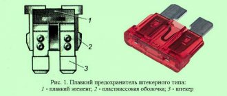
In the Mitsubishi Lancer IX, as in any other car, fuses are used to protect electrical equipment from damage due to a short circuit or overload. Therefore, each electrical circuit of the car must be protected by a separate fuse. The absence of fuses or the installation of fuses of a different rating can lead to serious consequences - from failure of the electrical system to fire. The term fuse most often means the most commonly used and at the same time the cheapest fuse, in which the destruction of the current-carrying element occurs as a result of exceeding the nominal current values, many call this process “burnout” or “combustion”. More information about fuses can be found on wikipedia.org. If a recently installed new fuse blows again after some time, it is best to contact a technician to determine the cause of the problem and fix it. Never install a fuse with a higher rated current in place of a blown fuse, or any substitutes (wire, foil, etc.). This may cause the wiring to overheat or cause a fire.
Fuse box location
In the Mitsubishi Lancer IX, the fuse blocks are located in the engine compartment (under the hood) and in the passenger compartment (near the driver's left foot).
The interior fuse box is located inside the storage compartment located in front of the driver's seat.
The engine compartment fuse box is located in the engine compartment in the area of the left front wheel.
Rated currents of fuses
The rated currents of the fuses and the names of the electrical circuits they protect are indicated on the inside of the glove compartment lid or on the cover of the engine compartment fuse box (located in the engine compartment). Spare fuses are located in the storage compartment lid where the interior fuse box is located.
Interior fuse box
Depending on the configuration, some fuses may not be included in the interior unit.
| 1 | Ignition coil | 10 A |
| 2 | Instrumentation | 7.5 A |
| 3 | Reverse lamp | 7.5 A |
| 4 | Cruise control | 7.5 A |
| 5 | Relay | 7.5 A |
| 6 | Electrically heated exterior mirrors | 7.5 A |
| 7 | Windshield wipers | 20 A |
| 8 | The engine control unit | 7.5 A |
| 9 | Cigarette lighter | 15 A |
| 10 | — | — |
| 11 | Electric exterior mirrors | 7.5 A |
| 12 | The engine control unit | 7.5 A |
| 13 | Car radio | 10 A |
| 14 | Rear window wiper | 15 A |
| 15 | Centralized door locking system | 15 A |
| 16 | Rear fog light | 10 A |
| 17 | — | — |
| 18 | Interior lighting | 10 A |
| 19 | Heater | 30 A |
| 20 | Rear window defroster | 30 A |
| 21 | Electric drive for the top hatch | 20 A |
| 22 | Electric seat heating | 10 A |
| 23 | Evaporative type intercooler | 10 A |
| 24 | — | — |
| 25 | Spare fuse | 20 A |
| 26 | — | — |
| 27 | Spare fuse | 30 A |
Engine compartment fuse box
Depending on the configuration, some fuses may not be in the engine compartment.
| 1 | Accumulator battery | 60 A |
| 2 | Engine cooling fan motor | 50 A |
| 3 | Anti-lock braking system (ABS) | 60 A |
| 4 | Egnition lock | 40 A |
| 5 | Power windows | 30 A |
| 6 | Front fog lights | 15 A |
| 7 | Sound signal | 10 A |
| 8 | The engine control unit | 20 A |
| 9 | Air conditioner compressor | 10 A |
| 10 | Brake lights | 15 A |
| 11 | Additional electrical outlet | 15 A |
| 12 | Generator | 7.5 A |
| 13 | Hazard warning lights, | 10 A |
| 14 | Automatic transmission (AT) | 20 A |
| 15 | Fuel pump | 15 A |
| 16 | High beam right headlight | 10 A |
| 17 | Left high beam | 10 A |
| 18 | Low beam right headlight | 10 A |
| 19 | Low beam left headlight | 10 A |
| 20 | Right side lights | 7.5 A |
| 21 | Left side lights | 7.5 A |
| 22 | Interior lighting | 10 A |
| 23 | Car radio | 10 A |
| 24 | Audio amplifier | 20 A |
| 25 | Electric seat heating | 20 A |
Power circuit protection
Where is the fuse for the cigarette lighter in Ford Focus 2 (restyling) and what is the article number?
In Mitsubishi Lancer cars of the IX and X generations, the protection of electromechanical and electronic devices from damage caused by overload or short circuit in the power supply circuits, as well as in other models, is carried out using fuse links, combined according to functionality and placed in close proximity to the protected units.
The fuse blocks of Lancer 9 and 10 cars are located both in the passenger compartment and in the engine compartment.
Central fuse block
The central fuse box in Lancer 9 and 10 cars is installed in the passenger compartment and is hidden under the dashboard (on the left side at the driver’s feet) behind a drawer for small items.
In order to gain access to the fusible links located inside the car, you must:
- open the box lid;
- pull the drawer towards you;
- overcome the force of the latches to remove the drawer.
After the drawer for small items is removed, access to the Lancer's central fuse box opens.
In addition to fuse links, it contains blocks for connecting harnesses and relays:
- Front fog lights.
- Reserve.
- Electric fuel pump.
- Heated front seats.
- Electric fuel pump.
- Electric windows.
- Connectors.
- Electric fan of the power unit.
- Rear window defogger.
The purpose of electrical circuits that are protected by fuse links are given in the table:
Fuses in the engine compartment
Under the hood of the Lancer are located:
fuse link 26 installed on the “+” terminal of the battery;
mounting block installed above the left front wheel (indicated in the photo as number 7).
Structurally, it is made of two parts, access to which is closed by a common lid. Below it are:
Main block (10), the arrangement of elements in which is shown in the photo:
The on-board electrical circuits, which are protected by fuses installed under the hood, are described below:
Additional block (11), which contains:
- block to which a device is connected that measures the crankshaft speed of the power unit (1);
- ignition system relay (5);
- automatic transmission control relay (6);
- main relay of the motor control system (7);
- relay that turns on the air conditioning compressor.
There are also spare sockets for installing relays (2. 4).
MOUNTING BLOCKS
Always carry a set of spare fuses with you - one of each rating.
Do not skimp when purchasing fuses: lately, low-quality fuses are often found on sale, the electrical parameters of which do not correspond to the declared ones. Remember that fuses are designed to prevent electrical fires and your life, not to mention the cost of car repairs, may depend on their quality under certain circumstances.
Rice. 10.1.
Mounting block located in the engine compartment
FUSE AND RELAY LOCATION
Most fuses and relays are located in a separate block located in the engine compartment of the car (Fig. 10.1).
Auxiliary relays are located in an additional mounting block (Fig. 10.2), located next to the main one. Some of the fuses and relays are located in a block located under the instrument panel on the left side of the steering column (Fig. 10.3).
The mounting block (see Fig. 10.1), located in the engine compartment, contains the following relays and fuses:
1–15 A fuse (circuit of the front fog lights, their turn-on indicator and the fog light turn-on relay);
2–10 A fuse (horn circuit and relay for its activation);
3rd place for the front fog lamp relay;
4 – fuse 20 A (circuits of the mass air flow sensor, crankshaft position sensor, recirculation valve, electronic engine control unit, engine control system relay, electric fan relay, idle speed control, ignition coil relay, electronic immobilizer control unit, injectors, concentration sensor oxygen and canister purge valve);
5–10 A fuse (air conditioning compressor circuit);
6–relay for turning on sound signals;
7–15 A fuse (circuits of the ABS electronic control unit, electronic engine control unit, additional brake light and rear lights);
8 – reserve place for relay;
9–15 A fuse (connector for additional electrical devices);
10 – reserve space for relay;
11–7.5 A fuse (generator excitation winding circuit);
12 – reserve space for relay;
13–10 A fuse (circuits of the electronic control unit of the ETACS system and direction indicators);
14–20 A fuse (automatic solenoid control unit circuit
15–15 A fuse (fuel pump circuit);
17–fuse link 40 A (ignition switch circuit);
18-fuse link 30 A (power window circuit);
19–10 A fuse (circuits of the instrument cluster, steering column switch, electronic control unit of the ETACS system, front electronic control unit);
20–10 A fuse (clock circuit, ETACS electronic control unit, radio);
21 – fuse 7.5 A (circuits of the electronic air conditioning control unit, ashtray illumination, cigarette lighter illumination, instrument cluster,
switch for fog lights, direction indicators, air recirculation control unit, rear lights, connector for radio);
22–7.5 A fuse (instrument cluster circuits, side lights and license plate lights);
23–10 A fuse (right headlight circuit);
24–10 A fuse (circuit of the left headlight and electric headlight corrector);
25-electronic lighting control unit;
26 – relay for turning on the fan electric motor;
27 – fuse link 60 A (ABS electronic control unit);
28-fuse link 50 A (fan controller circuit);
29–10 A fuse (circuit of the left headlight and the high-beam headlight signal lamp);
30 – 10 A fuse (right headlight circuit);
31–fuse link 60 A (battery charging circuit);
32 – 15 A fuse (circuits of front fog lights, warning lamp and relay for turning them on).
Fuses of different ratings are painted in different colors; In addition, the fuse is marked with a numerical value of the current for which it is designed (rated value).
COLOR OF THE FUSE CASE AND ITS COMPLIANCE WITH THE RATING
**The fuse is larger than the others.
Rice. 10.2.
Additional mounting block located in the engine compartment
Rice. 10.3.
Mounting block located inside the car
Table 10.1 FUSES OF THE INSTALLATION BLOCK
LOCATED IN THE VEHICLE PASSENGER
Changing the fuel filter in Mitsubishi Lancer
Often, many car enthusiasts forget to replace the fuel filter on time. This can lead to various malfunctions in the fuel system, and subsequently to interruptions in engine operation and its complete stop.
According to instructions from the Mitsubishi car manufacturer, the fuel filter for Lancer 9, Lancer 10 and Lancer X should be replaced after 120 thousand kilometers. However, there is one significant point that darkens this rosy picture completely - this is the low quality of our fuel.
Much to our chagrin, in our country not a single person is immune from gasoline with various impurities, dirt, metal particles, squeaks and other elements that can harm various systems of your car.
According to Russian standards, the allowed content of impurities in fuel is from 100 to 450 grams per 1 ton.
However, research work has demonstrated that over 5 thousand kilometers, the filter has the ability to accumulate about 50 grams of dirt. In accordance with this, replacement must be carried out much earlier than the mileage of your car approaches 120 thousand kilometers. The main signs with the appearance of which it is necessary to replace the Lancer fuel barrier (9,10, X):
- the engine does not start the first time;
- the car's power has decreased;
- in case of sudden acceleration, the engine stalls;
- uneven operation at idle.
But here you need to be careful, since the fuel pump and the dirty air filter of your Lancer may show similar signs. If you notice that fuel consumption has increased and black smoke is coming out of the exhaust pipe, this means that the air filter is faulty.
In all other cases, the issue will be in the fuel filter. To change it, you must first purchase it. Here a lot depends on the state of your finances, since the official filter is very expensive.
But you shouldn’t be upset and you can get by just fine by purchasing a Chinese-made part, which is almost ten times cheaper.
New fuel filter
In order to save on filter replacement services, this work can be done independently. If you carefully read the instructions, it will take you no more than 30 minutes. Let’s say right away that the work on replacing the fuel purification barrier for the Lancer 9, Lancer 10 and Lancer X models is almost identical, so let’s look at everything using one example.
Before starting work, it is necessary to reduce the pressure in the system in advance. To do this, you need to stop the engine and let the car sit for several hours. This is in principle optional, but it won’t be superfluous. It is better when there is as little gasoline in the tank as possible, and ideally no more than a quarter. The car must be set to the handbrake and set to neutral speed.
Step-by-step replacement instructions
We remove the back seat. To do this, you need to pull it up from both sides, tearing it off its seats. Rear seat with sound insulation
We remove sound insulation. Four screws that need to be unscrewed
Unscrew the four screws. The fuel tank may be covered in dirt or debris. Be sure to clean everything with a brush and rag. This is necessary so that debris does not accidentally end up in the tank. Debris in the fuel tank
After completing the cleaning, remove the fuel supply and return hoses. Unscrew the six nuts
Here you need to act very carefully, since during the operation of the car they may well become stuck and unscrew along with the stud. To prevent this from happening, you need to spray them with WD-40.
The place where the filter was located
Remove the pressure plate. Remove the filter. Fuel filter
Let's take it apart. We change the fine filter, and, on the contrary, just clean the coarse filter. Fuel filter disassembled
We assemble everything in reverse order.
As you can see, there is nothing complicated in replacing the Lancer fuel cleaning element (9, 10, X). Any car enthusiast can do it without spending money on the services of a mechanic.
Causes of the problem
The fuel system is a very “sensitive” element of a car, akin to the human circulatory system, consisting of many parts designed to ensure a reliable and timely supply of fuel to the car’s engine. And if any even minor problems arise, a whole series of malfunctions can occur that can cause a lot of trouble to the car owner.
The most common reason is poor quality fuel. Yes, it is this that can most quickly damage the fuel system. Low-quality fuel contains a large number of harmful additives.
Very often, unscrupulous fuel suppliers use low-quality gasoline, for example, AI-92 class, add harmful additives to it and sell it as AI-95. The additives contained in this fuel are detrimental to the fuel system. The injectors, fuel pump and filter wear out much faster than they should.
Another reason for poor fuel system performance is dirt (sand suspension, etc.) getting into the fuel tank. Large objects cannot get there due to a specially installed filter, but small ones can easily.
Car salon
To gain access to the fuse mounting block located in the passenger compartment, remove the cover, overcoming the elastic resistance of the latches.
| Purpose of fuses in the block located in the interior of the Mitsubishi Lancer | |
| Protected circuit | Current, A |
| Heater (Fuse Link) | |
| Brake lights | |
| Rear fog light | |
| Windshield wiper | |
| Accessory circuits | |
| Electric door locks | |
| Audio system | |
| Control unit relay | |
| Interior lighting lamps (plafonds) | |
| Hazard warning lights | |
| Rear window wiper | |
| Instrumentation | |
| Cigarette Lighter Fuse/Power Socket | |
| Egnition lock | |
| Luke | |
| Exterior mirrors | |
| All-wheel drive system | |
| Reversing lights | |
| Power outlet | |
| Electric windows (Fuse link) | |
| Heated rear window (Fuse link) | |
| Heated exterior mirrors | |
| AC power supply | |
| Electric seats | |
| Seat heating | |
| Relay | |
| A | Optional equipment |
| B | Heater fan relay |
| C | seat heating |
| D | heated rear window |
Replacing the fuse in the cigarette lighter
If your cigarette lighter does not work, first check the 15A fuse in the passenger compartment. If it is intact, but the cigarette lighter still does not work, then most likely the fuse located in the cigarette lighter itself has failed and needs to be replaced.
Please note that a tin wire is used as a fuse in the cigarette lighter, which is designed for a certain load, above which the fuse must melt, thereby breaking the circuit. If you install a regular metal nail, aluminum or copper wire instead of a tin wire, then your new fuse will not work at the right time, and this can lead to a fire in the wiring.
Therefore, be careful and careful!
The following tools and materials were required for the work:
- wire cutters;
- a piece of tin wire with a suitable cross-section (please indicate in the comments the diameter of the original wire, measuring it with a caliper, after which you can determine its cross-section).
- flat screwdriver;
- 7mm head.
Repairing the cigarette lighter on a Mitsubishi Lancer 9, do it yourself.
I'm in May be useful: Do-it-yourself minor repairs. Cigarette lighter repair
on Mitsubishi...
Let's start replacing the fuse in the cigarette lighter
1. Pull out the trim, to do this we pull out the ashtray and pull out first one side then the other using the inner edges of the hole (marked the edges)
2. Disconnect the wires from the cigarette lighter
Wire 1 can be disconnected simply and freely.
Wire 2 is removed by twisting (like a marker lamp), i.e. turned it half a turn and pulled it out.
Wire 3 turned out to be the most difficult, it is difficult to get to it and it just doesn’t leave the contact; on the fastener there is a small button, when pressed, the wire will come off.
There is also a 4th wire, this is the one that goes to the ashtray illumination, it is unscrewed in the same way as the 2nd wire.
3. After disconnecting, you can unscrew the manual transmission knob, or you can unscrew the socket itself (I don’t know how). So I just unscrewed the handle and removed the cover along with the socket
4. We turn it over and see the nut number 7, unscrewing which we remove two plates, the contacts of which are connected by a small tin wire, attached by a plastic black platform, then simply using wire cutters we unbend the contacts and pull out the old wire, you can just barbarically bite the wires and pull out the rest, then for simplicity Use a screwdriver to disconnect the front plastic and plates. And so, we bend the contacts wider with pliers, cut off a new wire, in this case also tin, and press everything as it was, put it in the reverse order.
Point 4 is described, without a photo, but when you analyze it you will see and understand everything for yourself, there is nothing complicated.
The report used materials from the author “BlackSTW”, for which many thanks to him!
For modern car enthusiasts, this device has much more functionality than the name suggests. After all, many devices are connected to the cigarette lighter socket. The most common:
- charger or power bank for mobile phones, tablets or other electronic devices;
- a navigator showing the way through city traffic jams;
- DVR recording traffic conditions;
- fan;
- compressor for inflating wheels.
Therefore, when the Lancer 9 cigarette lighter stops working and needs to be replaced, this is unpleasant news. Making repairs yourself is not difficult. You can learn from this material how to find out the cause of the malfunction, check weak points, and repair the device.
Payment via Portmone
After selecting payment through Portmone, the payment system will launch, where you need to select the payment method: bank card or Portmone account.
The price in the Portmone payment system is converted into dollars at the exchange rate of the Central Bank of the country where you are located.
If you have a bank card in a currency other than the dollar, then the money will be debited from the card at the rate of the Central Bank of your country at the time of the purchase.
After specifying payment details and confirming payment, payment for the goods will occur.
This is interesting: Replacing an automatic transmission on a Chevrolet Cruze: repairing a tube and filter
Gasoline pump
Gasoline pump
#1 Unread message MobileMan » Wed Oct 03, 2012 1:49 pm
#2 Unread message leonec » Tue Oct 30, 2012 11:14 am
#3 Unread message LancerZ » Tue Oct 30, 2012 12:55 pm
#4 Unread message MobileMan » Tue Oct 30, 2012 1:05 pm
No matter how much I looked for information about the performance of Lancer pumps, I couldn’t find it. and the markings on the original pump are also nowhere to be seen
I’ll assume that the pump from 1.5 is different from 1.8 -2.0.
#5 Unread message LancerZ » Tue Oct 30, 2012 1:16 pm
#6 Unread message leonec » Tue Oct 30, 2012 1:27 pm
#7 Unread message MobileMan » Tue Oct 30, 2012 1:31 pm
#8 Unread message LancerZ » Tue Oct 30, 2012 1:36 pm
#9 Unread message MobileMan » Tue Oct 30, 2012 1:48 pm
#10 Unread message LancerZ » Tue Oct 30, 2012 1:58 pm
Well, what was your question in the previous message?
One and a half - VAZ is enough for her.
#12 Unread message temba » Tue Oct 30, 2012 2:45 pm
1.5 – 1760A271 2.0 – 1760A271
find 10 differences)) Identical pump assemblies are listed in the catalog!
temba wrote: 1.5 – 1760A271 2.0 – 1760A271
find 10 differences)) Identical pump assemblies are listed in the catalog!
#14 Unread message LancerZ » Tue Oct 30, 2012 5:56 pm
#15 Unread message LancerZ » Fri Nov 09, 2012 8:56 am
For those who do not accept OEM Denso used, here is a likely replacement:
Airtex Electric Fuel Pump – E8548
According to the characteristics, according to unverified information (the manufacturer is silent), it is not very bad:
“GPH (Free Flow) Rating: 45-55 gph Hardware Included: Yes Marine Approved: No Pressure Rating: 70-90 PSI”
But I am for Denso, because it is reliability and quality.
Design and principle of operation
To find the reason why the cigarette lighter does not work, you need to understand its structure and principle of operation. The small device is made in a plastic case, inside of which there is a metal spiral. The functions of the heating element are performed by nichrome or other material with increased resistivity. The product is connected to the corresponding socket on the dashboard, and the positive contact is connected to the heater.
When heated, the nichrome spiral turns red. The system is equipped with a thermal relay that turns off the power supply when the permissible temperature threshold is exceeded.
The cigarette lighter socket is illuminated, so finding it in poor lighting conditions is quite easy. There is also a 10 A fuse in the socket.
Before turning to specialists with the question of why the cigarette lighter stopped working, you should consider the main reasons for this incident.
What to do
Fixing cigarette lighter breakdowns does not take much time. However, the car owner needs to get a general idea of the repair and draw up a step-by-step action plan.
The simplest solution is to seek help from specialists. An experienced service center employee will return the product to working order in a short time. However, you will have to pay for such a service.
To do all the work yourself, follow the following instructions:
Make sure that the fuse is in the correct place. According to the diagram, it should be fixed in a common box and indicated by the symbol of a smoking cigarette or the inscription “Cigar”. If a part fails, replace it with a new one. If the product is working properly and continues to conduct current, evaluate the condition of the socket. Pay attention to the interior of the nest. It may be clogged with some debris. To remove a foreign object from the slot, you need to use tweezers
However, the action must be performed with extreme caution.
If there are traces of burning on the cigarette lighter, you will need to buy a new product. If there is a soldered wire, it is enough to solder it.
Required Tools
To repair the cigarette lighter, you should prepare the following tools:
- Tweezers.
- Screwdriver (phillips or flathead).
Also, a flashlight, a multimeter and a printed wiring diagram may be useful for the upcoming work.
How to remove the cigarette lighter
If you have found the cause of the cigarette lighter failure and prepared the necessary equipment, proceed to disassemble the part. The dismantling process involves the following steps:
- First you need to open the hood and remove the negative terminal from the battery.
- Next, you need to disassemble the facing panel to gain access to the socket connection connector.
- Then you can unscrew the screws and disconnect the block.
- The next step is to dismantle the metal cigarette lighter tube using a screwdriver.
- After removing the part, you must turn off the backlight.
Car cigarette lighter button repair
Often the device stops working due to damage to the power button.
The repair process does not take much time and is done with your own hands.
Cigarette lighter head repair
In some cases, it is necessary to perform partial repairs of the car cigarette lighter. To do this, the element is dismantled according to simple instructions and checked for defects under the housing. Inside the part there is a miniature mica plate, which acts as a semiconductor and often fails. The product must be removed, repaired, and then put back.
