01/25/2022 12,025 Transmission
Author: Victor
It is necessary to adjust the clutch on KamAZ 5320 and other models to maintain the good condition of the truck. Sometimes the need to carry out such work may arise on the road, so it is advisable for the car driver to know the basic conditions for independently and correctly setting up the mechanism.
[Hide]
Design features of the clutch
The bulk of KamAZ trucks use a double-disc clutch with a radial arrangement of power springs. To operate the mechanism, a hydraulic drive with a pneumatic amplifier is used. Thanks to this design, the force required to press the clutch pedal is significantly reduced. During the operation of KamAZ, wear occurs on the clutch discs, which must be compensated for by adjustment. Correct adjustment of the mechanism ensures the fuel consumption declared by the factory and confident acceleration of an empty or loaded vehicle.
KamAZ clutch drive mechanism diagram
The main components of the drive, which is shown in the photo, are:
- pedal (1);
- hydraulic unit (2) with reservoir (3);
- highway (6);
- executive pneumatic cylinder (16).
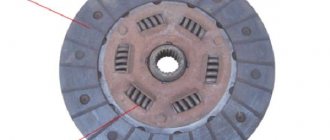
The KamAZ clutch of models 55111, 5320, as well as 43118 and 740 consists of the following structural units:
- clutch housing (A);
- release disc with stamped metal casing (B);
- pressure springs (B) and levers (D);
- one drive disk (E);
- two driven disks (D) with linings (W).
Clutch diagram for KamAZ 740 with diesel engine
The driven discs in the clutch design of a KamAZ truck are made using heat-resistant friction linings, which ensure a long service life of the mechanism. The design of the disks provides a damper for vibrations that occur when the motor shaft rotates. The drive pedal is mounted on special bushings and rarely requires lubrication during operation.
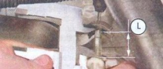
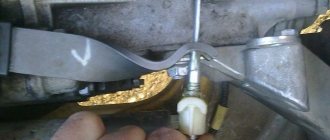
On more modern KamAZ models, single-disc clutches of the so-called Euro type are used. This mechanism is found, for example, on models 6520 or 4308. The supplier of elements for such units is Sachs, and amplifiers made by Wabco are used. There are several clutch models that differ in the amount of transmitted torque. One of the differences between imported amplifiers is the built-in indicator of friction lining wear. Wear is measured by the distance between the amplifier body and the washer on the rod. When the linings are completely worn out, this distance ranges from 23 to 25 mm. In this case, driving a car is still possible, but repair work must be carried out urgently.
Wabco CCGT unit, the wear indicator rod is visible in the upper left part
On some KamAZ models, for example, on 43114, there may be a PGU manufactured by the Volchansky Automotive Unit Plant, in which there is no possibility of adjusting the rod. Typically, such a PGU is either replaced with a customizable one or another rod with adjustability is installed.
How to know when it's time to change your clutch
There are cases when adjusting the clutch cannot correct the problem. Perhaps you missed a moment when you could get by with little effort, or maybe the device failed for some objective reason. So, it’s time to change the MAZ clutch if you notice the following signs:
- The device turns on abruptly, the car jerks and abruptly pulls away.
- Noise in the mechanism, perhaps a loud cracking sound when the gear is engaged.
- The car starts moving late, even if you release the clutch on time.
- A characteristic burning smell in the cabin (this is a clear sign that the clutch has burned out).
There is no need to delay replacing the clutch. As a result, everything may end in damage to the gearbox or in the fact that one fine day the car simply will not be able to move.
However, if you are confident in your abilities or the KamAZ clutch basket is familiar to you, you can get down to business.
What you need
Before starting work, you need to stock up on a certain set of tools. So, you will need:
- A set of wrenches or socket heads.
- Emphasis.
- A ruler to later measure the free play of the pedal.
- Pliers and pliers.
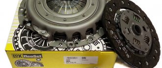
Replacing the Kamaz clutch
If you have all this, it's time to get to work. The main thing is to strictly follow the entire sequence of actions:
- First of all, remove the gearbox. KamAZ has it very heavy, so you will need the help of several people.
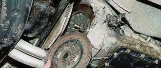
- Next, next is the clutch basket, remove it too.
- Then remove the driven, middle and driving clutch discs.
- Then install new parts of the device in their place. Start by installing the first driven disk and then install the parts in the reverse order of disassembly.
- Make sure once again that the device is assembled correctly and that’s it – you can put the gearbox in place.
If the clutch is single-plate, the process is similar and even easier. It may seem that everything is quite simple, but this is far from the case. Replacing and adjusting the MAZ clutch will require a lot of physical effort and time. Perhaps it makes sense to trust specialists who will do everything correctly and without mistakes. By observing the process, you will be able to remember the entire sequence in practice, and next time you will be able to adjust or replace the device yourself.
How to use the clutch to make it work as much as possible
There are several simple rules to extend the life of the KamAZ clutch. Unfortunately, not all drivers use them and often the device has to be changed much earlier than provided by the manufacturer.
- Do not keep the mechanism depressed for too long. Using clutch slipping at traffic lights and to reduce speed is very harmful to the device.
- And, most importantly, check the free play of the pedal as often as possible and lubricate all accessible components of the clutch mechanism. This is probably the most important guarantee that you won’t have to think about replacing the mechanism for at least several years.
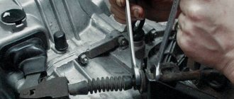
Adjusting the legs of the KAMAZ clutch basket
The case is carried out in several steps:
- The checkpoint is dismantled. Use wrenches to unscrew the fastening bolts.
- Raise the box: it is better to do this with a cargo winch.
- Check the condition of the coupling, tension spring element, and release bearing.
- Unscrew the screws connecting the pressure plate and flywheel. To dismantle the pressure element, the driven disk must be supported.
- Carry out troubleshooting of all parts of the system (preferably).
- Check the condition of the release bearing. A working mechanism rotates easily, without unnecessary sounds.
- Conduct a visual inspection of the working surface of the pressure plate feet. After installing the new parts, the KS feet are adjusted. In this case, you will need a flat slab.
The location of the paws is oriented towards the working position of the pressure plate surface
Important: the operation does not require removing the joint from the additional flywheel. You will need wrenches for the adjusting screws.
The KS feet must be positioned so that the distance from the working plane of the pressure plate to the upper edges of the spherical protrusions on the inner surface of the feet is no more than 41 millimeters. But 40 mm is better.
To check the installation of the paws, you will need a special plate. The spherical protrusions must touch the control plate (it is installed on the hub). After completing the adjustment, all screws securing the support plates are tightened until they stop. Assembly proceeds in reverse order.
How is the adjustment carried out?
If problems occur with the clutch, you should try to make adjustments. When disc slippage occurs (sluggish acceleration, slight burning smell), it is necessary to set the correct clutch stroke.
If the disks are not fully spaced (difficult switching), you will have to perform more operations:
- Set the pedal stroke.
- Remove air from the drive lines.
- Check the liquid level in the PSU.
When using the Euro unit, only the pedal free play needs to be adjusted. Lubrication and adjustment of other clutch parts during operation of the machine is not provided, except for monitoring the height of the fluid level in the drive reservoir.
By adjusting the clutch on KamAZ 5320 and other models we mean setting the correct gap between the release plate plane and the lever heads, as well as adjusting the free play of the pedal and drive clutch. The permissible free play for the clutch pedal must be in the range from 6 to 12 mm.
The gap is understood as the distance between the points of the central part of the pedal platform when the pedal is released and at the moment the master cylinder begins to turn on. The free play is regulated by rotating the eccentric pin located in the connection of the pedal lever with the upper eye of the amplifier rod. The adjustment is made with the pedal tension spring fully depressed, i.e. the pedal should rest against the upper rubber buffer, which serves as a travel limiter.
For example, on KamAZ 65115 the do-it-yourself adjustment process is as follows:
- Unlock the pin castle nut pin.
- By rotating the finger you need to achieve acceptable free play.
- Tighten the nut and secure it with a cotter pin.
- Check the pedal's full travel. If everything is adjusted correctly, it should be between 185 and 195 mm.
On single-disc MFZ units, the adjustment is similar, but the pedal travel should be from 140 to 150 mm.
Below, the process of adjusting the free wheel is demonstrated using the example of KamAZ 4310, the author of the video is Vladimir Krasikov.
Clutch of KamAZ-4310 and URAL-4320 vehicles
Military Encyclopedia - historical and archival military-patriotic portal
home☆Soviet military encyclopedia☆military equipment☆military science☆military review☆history of weapons☆forum
military equipment ☆ articles on the VAT device ☆
On KamAZ-4310 and Ural-4320 vehicles, a friction dry double-disc clutch with a peripheral arrangement of springs is installed. The clutches of both cars are the same, their parts are interchangeable, the difference is in the drive. On the KamAZ-4310 vehicle the clutch drive is hydraulic with a pneumatic booster, on the URAL-4320 vehicle the clutch drive is mechanical.
The clutch is called frictional and dry because the transmission of torque in it is carried out due to the friction forces between the disks, the surface of which must be dry; the disks are compressed by springs located along the periphery of the disks; The torque is perceived by two driven disks.
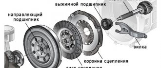
Rice. 96. Clutch mechanism for KamAZ-4310 and URAL-4320 vehicles : 1 - flywheel; 2 — middle disk; 3 — driven disks; 4 - crankcase; 5 — pressure disk; 6 - casing; 7 — support fork; 8 — adjusting nut; 9 — lock washer; 10 - locking plate; 11 — pull lever; 12 — lubricant supply hose to the clutch release clutch; 13 — clutch release; 14 — clutch release fork; 15 - thrust ring; 16 – fork shaft; 17 — pressure spring.
The clutch parts are located in an aluminum housing 4 (Fig. 96), bolted to the flywheel housing. On top of the crankcase there is a hatch for inspection of clutch parts; the hatch is closed with a lid. The bottom of the crankcase has two hatches, also closed with lids. A crowbar is inserted through the front (small) hatch to rotate the flywheel. The rear hatch cover has a threaded hole for grease drainage; Before crossing the ford, this hole is closed with a plug screwed into the blind boss of the lid. The clutch consists of driving and driven parts, a pressure device and a release mechanism with a drive.
The leading parts include flywheel 1, casing 6, pressure disc 5 and middle disc 2. The stamped casing is installed on flywheel 1 using mounting bushings and secured to it with twelve bolts. The pressure and middle disks each have four protrusions on their outer surfaces that fit into the grooves of the flywheel. Torque is transmitted through the protrusions from the flywheel to the discs; This installation of the disks allows them to move axially when the clutch is disengaged.
The protrusions of the middle disc house a lever mechanism that automatically adjusts the position of the disc when the clutch is disengaged. This mechanism consists of a lever with an axis and a spring. The lever axis is screwed into the hole in the protrusion and secured against turning with a rivet. The lever is placed loosely on the axle and is pressed by a spring, one end of which rests against the plane of the groove, the other against the hole in the lever. The spring constantly strives to rotate the lever around the axis, while one end of the lever rests against a cracker pressed into the flywheel, and the other against a specially hardened place on the pressure disk. When the clutch is released, the lever mechanism sets the disc to the middle position and ensures clean disengagement.
The driven parts include two driven disk assemblies 3, installed on the splines of the gearbox drive shaft. Each driven disc consists of a steel split disc, two friction linings, a hub and a torsional vibration damper. Cutouts on the steel disk increase its elasticity and protect it from warping when heated. The friction linings are made of an asbestos composition and riveted to the steel disc with non-ferrous metal rivets. The steel split disk, together with the friction linings, is connected to its hub through a torsional vibration damper.
Torsional vibrations occur on the crankshaft and transmission shafts from uneven engine operation, when the clutch is abruptly engaged, or when the vehicle moves over uneven surfaces.
The torsional vibration damper consists of two rings with friction linings, two disks, eight cylindrical springs and two disc springs that press the damper disks against the friction rings. The transmission of torque through the cylindrical springs of the damper prevents the possibility of high-frequency vibrations occurring on the shafts; low-frequency vibrations that may arise in this case are damped due to friction between the discs and the friction linings of the damper rings.
The pressure device includes twelve cylindrical springs 17 located between the casing and the pressure disk; A washer and a heat-insulating ring are placed under each spring on the pressure plate side. The total spring force is 10.5…12.0 kN.
The release mechanism includes four levers 11 with a thrust ring 15, a support fork 7 with a nut 8, a clutch 13 with an angular contact bearing, a release fork 14 with a shaft 16. Each lever is mounted on a needle bearing in the support fork, the outer end
The lever is attached to the lugs of the pressure plate through a needle bearing. The nut 8 of the support fork 7 has a conical flange and rests on a plate 10 of a wavy profile, which, together with the support lock washer 9, is attached to the casing b with two bolts. A thrust ring is pressed against the inner ends of the levers 11 using springs and hinges. Clutch 13 is pulled to the rear position by two springs.
Clutch operation. In the on position, the driven disks 5 are clamped between the flywheel, the middle disk and the pressure disk by the force of the pressure springs. Between the thrust ring 15 and the release clutch bearing, a gap of 3.2...4.0 mm is established. Torque is transmitted from the flywheel through the protrusions to the middle and pressure plates. From the working surfaces of the flywheel, middle and pressure disks, due to friction forces, torque is transmitted to the friction linings of the driven disks and then through the torsional vibration dampers to the drive shaft of the gearbox. All clutch parts, except the release clutch, rotate as one unit.
When the clutch is disengaged, the force from the drive is transmitted to the clutch 13, which moves forward and after selecting the gap, the clutch bearing presses the thrust ring 15 and the levers 11 associated with it. The latter rotate relative to the support fork 7, while the outer ends of the levers move the pressure plate back. The middle disc is self-aligned between the flywheel and the pressure plate using a lever mechanism. A gap forms between the rubbing surfaces of the clutch, and the transmission of torque from the driving parts to the driven parts stops.
When the clutch is engaged, clutch 13 returns back with the force of its springs, the pressure springs again press the drive and driven disks against the flywheel, and torque transmission resumes. Since all the rubbing surfaces do not come into contact with each other instantly, the increase in torque transmitted through the clutch occurs with some slowdown, which ensures smooth engagement of the clutch. This is also facilitated by the smooth release of the clutch pedal.
Rice. 97. Clutch drive of a KAMAZ-4310 vehicle : 1 - pedal; 2 - lower stop; 3 — bracket; 4 - upper stop; 5 — lever; 6 - eccentric pin; 7 — piston pusher; 8 - spring; 9 — main cylinder; 10, 14 - pipelines; 11 — pneumohydraulic booster; 12 - plug; 13 - bypass valve; 15 - protective: cylinder; 16 — piston pusher; 17 — adjusting nut; 18 — compensation tank
If the transmission is overloaded, the drive disks slip relative to the driven ones, which protects the engine crankshaft and transmission parts from twisting and damage.
The clutch drive of the KamAZ-4310 vehicle is hydraulic with a pneumatic amplifier. The drive consists of pedal 1 (Fig. 97) with spring 8, main cylinder 9, pneumatic-hydraulic booster 11, pipelines and hoses. The clutch pedal is installed on the axis of bracket 3, mounted on the front panel of the cab. The pedal rotates relative to its axis on two metal-plastic bushings. The 5th axis lever is connected to the master cylinder pusher using an eccentric pin b installed in two nylon bushings.
Rice. 98. Main cylinder : 1 - pusher; 2 - body; 3 - piston; 4 — tank body; 5- cork barrel; A - gap.
The clutch master cylinder consists of a housing 2 (Fig. 98) with a plug, a piston 3 with a rubber collar, a pusher 1 and a spring.
The internal space in the housing is divided by a partition into two cavities - working and compensation. A piston with a cuff and a spring are installed in the working cavity. The compensation cavity is designed to store a supply of working fluid. The upper part of the case is covered with a rubber boot.
When the clutch pedal is released, pusher 1 is in the upper position. Piston 3 is pressed against the housing partition by spring force. A gap is established between the pusher and the piston and both cavities communicate with each other through a hole in the piston.
When you press the pedal, the pusher selects a gap, closes the hole in the piston and moves it; pressure is created in front of the piston, which is transmitted through pipelines to the pneumatic amplifier.
The pedal stroke at which the clearance in the clutch drive is selected is called free play. The pedal stroke after selecting the gaps all the way is the working stroke. Free and working travel form the full travel of the clutch pedal.
The main cylinder is connected by a tube to tank 4, closed with plug 5. The hydraulic drive is filled with GTZh-22M or Neva brake fluid in the amount of 0.28 liters. The normal liquid level in the tank should be no lower than 15...20 mm from the upper edge of the filler neck of the tank.
Rice. 99. Pneumohydraulic amplifier of the clutch drive of the KamAZ-4310 vehicle: 1 - spherical nut with locknut; 2 - pusher; 3 — protective cover; 4 - hydraulic piston; 3 — rear body; 5 - combined seal; 7 – follower piston; 8 - bypass valve; 9 - diaphragm; 10 — inlet valve; 11 — exhaust valve; 12 - pneumatic piston; 13 - plug; 14 — front body; A – hole for liquid supply; B - hole for air supply.
The pneumohydraulic booster (Fig. 99) serves to reduce the force on the clutch pedal. It is attached with two bolts to the clutch housing on the right side. Its main parts are: front 14 and rear 5 housings, pneumatic piston 12 with a pusher, cuff and return spring, hydraulic piston 4 with seals, spacer spring and pusher 2; tracking mechanism.
The front body is made of aluminum alloy, the rear body is made of cast iron; Each housing has two borings for installing pistons and follower parts. The housings are connected to each other with bolts.
Pneumatic piston 12 is installed in the front housing and sealed with a rubber cuff. A pusher, manufactured integrally with the hydraulic piston 4, and a return spring rest against the bottom of the piston. The space in front of the Piston is connected by an internal hole in the front housing to the cavity of the valves of the follower mechanism. Plug 13 serves to remove condensate from the cavity of the pneumatic piston.
Hydraulic piston 4 is installed in the lower bore of the rear housing, which acts as a cylinder; The seal of the hydraulic working cavity is ensured by a combined seal 6.
The follower mechanism is designed to change the air pressure in the space in front of the pneumatic piston in proportion to the force on the clutch pedal. This mechanism includes: a piston 7 with a cuff, a rubber diaphragm 9 with an exhaust valve seat, a diaphragm spring, conical inlet 10 and exhaust 11 valves.
Piston 7 moves in the rear housing and rests against the exhaust valve seat. The cavity of the piston 7 of the follower mechanism is connected to the cavity of the hydraulic piston 4 by an internal channel. Diaphragm 9 is clamped by its edges between the front and rear housings by pneumatic amplifiers. The exhaust valve seat 11 is fixed in the center of the diaphragm. The spring presses the diaphragm to its extreme position, the conical inlet and exhaust valves are assembled on a common rod on which the spring is placed. The cavity in front of the diaphragm is connected by a calibrated hole to a channel for supplying air to the pneumatic piston.
The working fluid from the main cylinder enters the hydraulic piston cavity through hole A in the rear housing. Compressed air from the car's pneumatic system is supplied to the pneumatic booster through hole B. Air is released into the atmosphere through a seal located on top of the follower mechanism. Bypass valve 8 serves to release air when pumping the hydraulic drive.
When the clutch pedal is released, the diaphragm of the follower mechanism, together with the exhaust valve seat 11 and piston 7, is moved back (to the left), the exhaust valve is open, the intake valve is closed. The space in front of the pneumatic piston is connected to the atmosphere; pneumatic piston 12 is in the extreme forward position under the action of the spring.
When you press the pedal, the working fluid from the main cylinder enters the cavity in front of the hydraulic piston 4 and through the channel in the rear housing 5 to the piston 7 of the follower mechanism. Piston 7 together with the diaphragm moves forward, exhaust valve 11 closes, and with further movement, inlet valve 10 opens and compressed air enters the cavity in front of the pneumatic piston. The forces created by the pneumatic and hydraulic pistons are summed up and transmitted through pusher 2 to the clutch release fork lever.
At the same time, compressed air enters the cavity in front of the diaphragm, which, as pressure increases, bends back, and the inlet valve closes. When you press the pedal further, a new portion of air will flow to the pneumatic piston. This ensures proportionality between the force on the clutch pedal and the air pressure on the pneumatic piston.
Adjustments of the clutch of the KamAZ-4310 vehicle. The free play of the clutch pedal should be 30-42 mm, which is ensured by the gap between the release pin bearing and the thrust ring of the levers and the gap between the pusher and the master cylinder piston.
The gap between the clutch bearing and the thrust ring is adjusted using spherical nut 1 of the pneumatic booster piston pusher. The size of the gap is judged by the free play of the clutch fork shaft lever, which should be 3.7...6.5 mm. The free play of the lever is checked at a radius of 90 mm. The indicated free play of the lever corresponds to a gap between the bearing and the ring of 3.2 ... 4.0 mm.
The gap between the piston and the master cylinder pusher is adjusted using eccentric pin 6 (see Fig. 97), with which the pusher is attached to lever 5. The pin should be turned so that the movement of the pedal from the top stop until the pusher touches the piston is 6...12 mm .
With a serviceable, pumped and adjusted drive, the full stroke of the pneumatic booster rod should be at least 24 mm, and the full stroke of the pedal should be 185...195 mm.
Rice. 100. Clutch drive of the URAL-4320 car : 1 - pedal; 2 - intermediate shaft; 3.7, 9, 11 — levers; 4. 5 - rods; 5 - servo spring; 6 — pedal shaft; 8 — pedal travel limiter.
The clutch drive of the Ural-4320 car is mechanical. It consists of pedal 1 (Fig. 100) with servo spring 5, four levers 3, 7, 9, 11; two rods 4 and 10, intermediate shaft 2 with bracket. The pedal is fixed to shaft 6 located in the pedal bracket. In the initial position, the pedal rests against limiter 8.
When you press the pedal, rod 4 moves upward, lever 3 with intermediate shaft 2 rotates clockwise, the lower end of the lever moves forward along with rod 10, which turns lever 11, and with it the shaft and fork 14 (see Fig. 96) . The latter acts on the clutch 13 to release the clutch.
When selecting free travel of the pedal, the driver expends some effort to stretch the servo spring 5 (see Fig. 100), which, when making a working stroke, helps the driver disengage the clutch.
Adjusting the cordon of the Ural-4320 car. The free play of the pedal should be 30-40 mm, which corresponds to the free play of the end of the lever 11 of the release fork shaft of 6.1-9.2 mm. The free play is adjusted by changing the length of the rod 10. If the thread of the rod is completely used, it is necessary to move the lever 11 to one slot.
Full pedal travel should be 195 mm, while full lever travel should be 34.6-45.8 mm. The full travel of the pedal is adjusted by turning in or out the limiter adjusting screw 8.
Tags: Kamaz 4310 ☆ car transmission ☆ Ural 4320 ☆ car device ☆
| General information about vehicle transmission and clutch < Prev. | Track. > Clutch of the ZIL-131 car |
Fast delivery of a tow truck to Shchelkovo
In Moscow and Moscow region
- Contacts:
- +7
- around the clock
- seven days a week
© Military Encyclopedia. Map of site.
Clutch debugging
The next stage of adjustment will be to adjust the free play parameters of the clutch, the value of which should be from 3.2 to 4 mm. The measurement is carried out by rotating the adjusting nut.
The sequence of actions in this case:
- Loosen the fork mounting nut.
- Unscrew the fastening pin, allow it to move freely and remove it.
- Rotate the traction fork until the required clearance is obtained.
- Tighten the nut and install the pin in place.
- Install the locking pin.
- Check the setting. When the pedal is fully depressed, the clutch stroke should be at least 25 mm.
Debugging the full stroke of the amplifier pusher
Before starting to debug the mechanism, it is necessary to find out the stroke length of the pusher. To do this, you need to completely disengage the clutch and measure the stroke. If its value is 25 mm or less, then the clutch will not disengage completely. The driver will notice this problem immediately by the difficulty of shifting gears. To find the cause of the problem, you need to check the level of working fluid in the pusher cylinder. The standard volume is 380 cubic meters. see. If the level of the substance is insufficient, it should be topped up.
Hydraulic system diagram
Using the KamAZ 5511 model as an example, adding fluid is done as follows:
- You need to open the reservoir cap located on the drive housing.
- Add liquid to a level 15-20 mm below the edge of the neck.
The second reason for unsatisfactory operation of the amplifier may be air in the system. In this case, the drive system must be bled. This procedure is somewhat more complicated.
On KamAZ 55102 for this you need:
- Add fluid to normal level.
- Remove the protective cap from the bypass valve (installed on the CCGT housing), put on a rubber hose and lower it into a container with liquid.
- Sharply press the clutch pedal all the way.
- Open the valve one turn and press the pedal until the substance stops bubbling at the outlet of the hose. In this case, it is necessary to constantly add new fluid to the supply tank, not allowing it to fall below the 40 mm mark from the top of the tank.
- Close the valve, remove the hose and replace the cap.
- Add fluid to the operating level.
- To control the quality of work, you must press the pedal all the way - the pusher stroke should not be less than 25 mm.
Preparing for adjustment
Before properly adjusting and bleeding the clutch on Kamaz 740, 5511 or other trucks, you must perform the following steps:
- Check the tightness of the drive device. To do this, you need to depress the clutch pedal several times. The presence of a serious air leak can be determined by hearing, and a weaker one can be determined by using a soap solution. If brake fluid is leaving the system, this can be determined visually. If problems are detected in the tightness, the components are tightened or the pipes are replaced.
- Carry out diagnostics of the fluid level in the expansion tank of the drive device. The volume of consumables should be about 15-20 mm below the edge of the tank neck. If required, the fluid level is replenished. It is not recommended to mix supplies from different manufacturers when performing this task.
- Check the operation of the pedal release springs, as well as the system release fork pulley lever.
- Tighten the bolts that secure the pneumatic reinforcement device CC. This procedure is performed using a torque wrench. The tightening torque should be about 90-100 Nm.
- Drain condensate, if any, from the pneumatic hydraulic booster.
Adjusting the clutch operation
To complete the task, you will need a special homemade product in the form of a piece of wire, one side of which should be 2 mm and bent at an angle of 90 degrees. The thickness of the rod is at least 3-4 mm. This size is optimal for controlling the gap between the tab outline and the disc release component. Adjustment is made using the nut of the pneumatic booster device. The legs must be brought to the ring through a hole located in the upper part of the crankcase.
You need to adjust the clutch like this:
- The locking screws are unscrewed with a wrench.
- The stoppers and plates are dismantled.
- Each nut is loosened and released 5 turns; for convenience, it is recommended to use a ratchet. If the penny protrudes beyond the surface of the ring, it must be recessed, checking in advance for the presence of ferodo at the bottom.
- When performing this task, you can also change the spring elements if they are worn out. The paws should be positioned so that they are in equal contact with the ring.
- The disk area runout is checked. If necessary, the bearing device is lubricated. The adjustment gap should be about 29-30 mm.
Adjusting the KamAZ clutch basket
By adjusting the clutch basket we mean adjusting the tabs placed on the basket. This debugging can be done with the box removed or adjusted directly on the car.
When performing the task without removing the box, you will need a homemade tool, which is a 3.5 mm thick wire with a 20 mm long end bent at a right angle. Using such an improvised feeler gauge, check the gap between the release bearing and the support ring of the clutch feet. The gap is adjusted using a nut on the PSU rod. You can bring the paws to the ring through the hatch in the upper part of the clutch housing. At the same time, it is important to ensure that the paws fit as uniformly as possible to the surface. But it is more correct and reliable to adjust the clutch removed from the engine.
- Place the assembled pressure plate on the template, which will provide a gap of 29 mm.
- Loosen the mounting bolts.
- Set the position of the stop ring for the feet. All four paws should touch the ring at the same time.
- Check the runout of the working surface of the disk.
- Lubricate the front bearing located in the crankshaft.
- Install the clutch using a mandrel, which will ensure alignment of the mechanism discs and the engine shaft.
This adjustment is carried out only with a double-disc clutch. A unit with one disk does not need such adjustment.
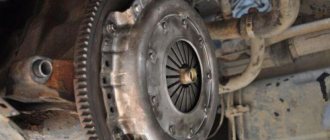
The video from the Auto and Moto channel shows the removal of the clutch and clearly shows the design features, as well as the drive for the operation of the mechanism.
Adjusting the clutch pedal free play
According to the official regulations, the stroke for moving the pedal should be about 6-12 mm, and the measurement itself should be done from the central component of the plate. The pedal must be released until the main cylinder starts working after pressing it. Adjustment is carried out using an eccentric pin; when making adjustments, the pedal must be pressed against the upper stop. The castle nut is tightened as much as possible and the full stroke is replaced, which should be 185-195 mm.
Video about adjusting the clutch pedal
The “EIGHT ATMOSPHERES” channel in its video showed in detail how to increase the clutch pedal pressure on a KamAZ Euro.
Maintenance
In addition to settings, the clutch of KamAZ vehicles requires regular maintenance, since this significantly increases the service life and reliability of the mechanism on all KamAZ brands.
Using model 53215 as an example, maintenance consists of the following main points:
- Checking the tightness of the amplifier mounting bolts in the clutch drive circuit.
- Monitoring the tightness of hydraulic lines. There should be no oil stains on them.
- General check of serviceability of pedal assembly parts. All elements must be in good condition and not have large gaps in the connections.
- Checking the presence of lubricant in the clutch bearing and fork connection bushing. To supply oil in the clutch housing there are three points equipped with grease nipples. Oil is injected into them using a syringe.
- Draining condensate from the CCGT housing.
- Checking the fluid level in the amplifier reservoir.
When is clutch replacement required?
If all the work performed does not lead to the restoration of the clutch mechanism, then this becomes one of the signals to replace it.
Other signs of critical wear of structural elements are:
- sudden turning on of the disks, resulting in a hard jerk of the car;
- difficulty engaging all gears, accompanied by a characteristic crash;
- sluggish acceleration of the car, while the engine speed clearly does not correspond to the selected gear and speed;
- smell of burning pads when driving.
If such problems occur, it is necessary to stop moving as soon as possible and repair the mechanism. Continued operation of the vehicle with faulty or burnt-out clutch discs will lead to failure of the gearbox.
Work related to clutch replacement
It is recommended to replace the basket if the following shortcomings are found:
- even after adjustment, the car jerks and starts abruptly;
- extraneous sounds in the basket were and are still present;
- the car “thinks” for a long time and does not immediately start moving, despite the fact that the clutch was depressed according to all the rules;
- There is a characteristic burning smell in the cabin - this indicates that the clutch mechanism has simply burned out.
Video “Adjusting the clutch on KamAZ”
The video, shot for the Auto and Moto channel, demonstrates the adjustment of the clutch installed on a KamAZ 740 diesel engine.
Reliability, excellent performance, efficiency - all this can be said about KAMAZ trucks. The machines are in demand for household, commercial and military purposes. The key to long-term and trouble-free operation is constant checking of the technical condition. Adjusting the KAMAZ clutch is always relevant. This brand is usually equipped with a dry double-disc or single-disc clutch (friction type). During its entire service life, the unit experiences enormous loads. Competent selection of spare parts and timely maintenance will guarantee long-term operation. Adjusting the KAMAZ clutch basket requires experience and certain knowledge.
Setting is necessary when:
- A crackling sound occurs when changing gears.
- Slipping at high speeds.
- Changing the free play of the clutch pedal (it has certain digital values).
If you ignore these signs, expect a serious accident!
We adjust the paws with our own hands
In Kamaz vehicles, the clutch performs the function of ensuring smooth starting of the vehicle, as well as disconnecting the engine from the transmission system when changing gears. The need to adjust the clutch basket feet (hereinafter referred to as the CS) in these car models is a common problem faced by many KamAZ owners.
Paws for KAMAZ clutch basket
The clutch in this car is an important and necessary component of the clutch system. Setting it up is an integral part of technical work, so KamAZ owners will not be able to avoid this activity.
What will you need?
Before we begin the repair work, we should prepare everything that we may need in the process.
- set of wrenches;
- flat slab;
- silicone glue.
KAMAZ clutch adjustment technology
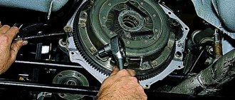
Removing and adjusting the KAMAZ clutch is carried out in several steps.
Adjusting the free travel of the KAMAZ clutch pedal
The pedal must have a play of 6 to 12 mm. Measurements are taken from the central part of the plate. The pedal must be lowered until the main cylinder starts working. If there is a deviation from the norm, adjust the distance between the PSU pusher and the stop at the top.
To do this, you will need an eccentric pin connecting the pedal to the top eye of the pushrod. The pedal for traction must press the clutch pedal against the stop from above. The finger is turned so that the gap between the piston and the PSU pusher is in the range from 6 to 12 millimeters. When finished, tighten the castle nut securely. The full pedal travel should be approximately 19 centimeters.
Adjusting the KAMAZ clutch
The manufacturer recommends maintaining a free play value in the range from 3.2 to 4 millimeters. To measure, you will need to move the fork shaft lever by hand. It must move in the direction from the spherical nut of the pusher. It is located on the pneumatic or hydraulic clutch drive amplifier. Adjusting the KAMAZ clutch clearance will require removing the spring: the lever should move no more than five millimeters. If the free play is less than three millimeters, then it is adjusted using a spherical nut. The idle speed of the clutch must be from 3.2 to 4 millimeters.
Adjusting the KAMAZ clutch drive
To measure the function indicator, it is worth pressing the pedal all the way. If the value is less than 24 mm, then complete shutdown will not occur. It is necessary to measure the free play of the pedal and the volume of fluid in the master cylinder. 380 cubic centimeters is the total volume in the hydraulic drive. If the data does not satisfy the requests, it is important to get rid of air in the system. This will return all indicators to normal.
Adjusting the KAMAZ clutch pressure plate
During this operation, you must strictly follow the sequence:
- Initially, the gearbox is dismantled. You can't do it without helpers.
- Remove the clutch basket.
- The clutch discs are dismantled: first the driven one, then the middle one, and finally the driving one.
- New parts are being installed. The order is already reversed.
- It is important to adjust the nickel of the KAMAZ clutch basket.
- The correct installation of all mechanisms is checked in detail.
- The gearbox returns to its place.
If there is only one disc in the clutch design, the job is much easier!
But even a KAMAZ single-plate clutch, adjusting its parts will require serious skills, strength and knowledge. Don't take risks - entrust the matter to professionals. Or do a one-time replacement with a real mechanic. For some mechanics, adjusting the KAMAZ double-disc clutch without removing the gearbox is a reality.
Installation of clutch discs.
Clutch disc hubs have a protrusion in one direction more than in the other. When installed, their large sides should face in different directions. Toward the flywheel
and towards the clutch basket. The first disk is installed with its larger side towards the flywheel. Next comes the intermediate clutch disc.
The second disc is installed with the larger side of the hub facing the basket. If at least one disk is installed incorrectly. They will bump into each other and the basket will not work.
The intermediate disk must move freely in the grooves of the flywheel. This is a very important condition. There should be no jamming or wedging. Otherwise, it will cling to some kind of disk. At least the disk won't be pressed too hard. But it will constantly rotate. And together with it the input shaft rotates. And you won’t be able to shift into gear without the gear crackling. It is better if the intermediate disk is a little free. A characteristic knocking sound when pressing the clutch pedal is heard on all KamAZ vehicles with two clutch discs. And it does not interfere with the clutch.
It happens that the clutch is adjusted correctly. The basket fully depresses the clutch discs. And when starting off, the transmission engages with a big roar. Or it may not be possible to turn it on at all. That's exactly why. That when the basket is depressed, at least one disk constantly rotates along with the flywheel. When the clutch is released, both discs should stop. Only then will the transmission shift into gear without any problems. And the reason for clutch malfunction is the intermediate disc. It jams in the grooves of the flywheel. Touches the disc. And the input shaft continues to rotate when the clutch is depressed. Therefore, it is very important to pay attention to how the intermediate disk is positioned.
After the cart is installed. It is necessary to correctly adjust the position of the clutch basket feet.
Design and principle of operation
The operation of the mechanism is based on the principle of sliding friction force.
The KamAZ clutch device is used for:
- transfer of rotation from the crankshaft;
- gradual transfer of gears;
- reducing rotational vibrations;
- disconnecting the transmission device from the engine for a short moment.
In a car, gear shift occurs when the clutch pedal is depressed, there is no connection between the engine and the gearbox, and rotation is not transmitted.
The KamAZ leaf clutch consists of the following parts:
- a flywheel that receives rotation from the engine and transfers it to the gearbox through the basket;
- pressure plate complete with springs;
- drive disk assembly with linings and vibration damper;
- plug assembly that breaks the connection;
- an axial shaft to which rotation is applied;
- release bearing;
- spring that reduces vibrations;
- hood;
- structural linings located on the drive disk to reduce friction.
How to extend clutch life
Timely maintenance extends the life of the basket, an expensive and complex mechanism. First of all, you need to know how to properly adjust the clutch on a KamAZ. Check the pedal travel from time to time, because you don’t need to disassemble anything to do this. All accessible mechanisms and components must be lubricated.
Holding the pedal down for a long time to stop, for example, to slip, is categorically not recommended - this increases the load on the mechanisms and, accordingly, accelerates their wear.
Ignoring detected clutch problems is guaranteed to lead to deterioration in the functionality of the entire machine. The logical conclusion of such neglect will be the failure of the gearbox, the repair or replacement of which will cost a tidy sum. Failures of other KamAZ transmission mechanisms and components are also possible.
How to adjust the KamAZ clutch
Maintenance is carried out regularly. Increasing the pedal stroke leads to incomplete disconnection of the flywheel and gearbox. This device causes the gears to come into contact, and the load on the teeth of the gears increases. If the accelerator stroke is insufficient, the drive disk does not engage, rotation is not fully transferred, and the machine stops.
Adjusting the clutch on a KamAZ allows you to eliminate faults that are diagnosed based on the following symptoms:
- at the beginning of departure - jerks;
- the friction pedal sticks;
- the accelerator is slow;
- if you check the drive fluid level, a leak is detected;
- extraneous sounds are heard.
The need to adjust the clutch on a KamAZ is checked by measuring the distance from the bottom of the pedal to the floor surface of the driver's seat - the indicator should be 16 cm.
Without removing the box
Adjustment of the clutch operation is carried out by removing the gearbox. But if adjustment is required under road conditions, then the work is performed without removing the structure.
You will need a homemade device in the form of a piece of wire, one side of which is 2 cm long and bent at an angle of 90˚. The thickness of the rod is at least 3-4 mm; this size is convenient for controlling the clearance between the disc release element and the contour of the legs.
The adjustment is made using the pneumatic booster nut. The legs are connected to the ring through a hole at the top of the crankcase. Elements are placed as equally as possible to the area.
The procedure is as follows:
- Unscrew the locking bolts.
- Remove stoppers and plates.
- The nuts are all loosened equally by 5 turns; ratchets are used for convenience.
- If a nickel protrudes beyond the surface of the ring, then it is recessed, first checking for the presence of ferodo underneath.
- The springs can be replaced at the same time.
- The paws are placed so that they touch the ring equally. Then the runout of the disc area is analyzed.
- The front bearing is lubricated. Select an adjustment gap of 29-30 mm.
Setting up the mechanism without removing the gearbox is done in the case of a double-disc clutch; single-disc clutches are not adjusted this way.
How to adjust pedal free play
Check the movement of the coupling by moving the axial shaft lever away from the pusher nut. If the free distance measured at 90˚ is less than 3 mm, then to adjust it, rotate the pusher screw so that the distance of free movement of the coupling is 3.1-4 mm.
The stroke of the amplifier pusher is checked when the accelerator is pressed - the indicator should be more than 2.5 cm. A smaller value does not ensure effective activation. If the pusher stroke of the pneumatic hydraulic booster is less than recommended, then:
- adjust the free play of the clutch pedal;
- control the amount of liquid in the main cylinder container;
- remove the atmosphere from the hydraulic device.
The pedal movement should correspond to the size of 6-15 mm, it is measured in the middle of the pedal. If it is exceeded, the clearance of the piston and pusher is set using an eccentric element connecting the hole at the top of the pusher and the accelerator.
How to adjust the cart
The basket's feet are adjusted on the removed disk or through a gap in the flywheel directly on the machine.
- When the machine is in the pit, remove the box using a winch.
- Inspect the release bearing, springs and collets.
- Unscrew the fastening of the disk to the engine flywheel.
- Remove the pressure mechanism while holding the drive disk.
- Inspect the surface and make adjustments to the paws relative to the area of the disk.
- Check the change in the position of the paws using a plate, taking into account that their round surfaces should touch the template located on the hub.
- After adjusting the clutch basket, the hardware is tightened until it stops. Clutch assembly is done in reverse order.
Clearance between release bearing and basket – Basket and release bearing
In the clutch drive in a classic VAZ with an original basket, original release cylinder and a conventional slave cylinder, there must be a gap between the pusher (rod) of the slave cylinder and the clutch fork. This clearance is required since the release bearing is not designed for constant operation and constant rotation. If there is no clearance, the bearing will constantly rest against the petals of the basket and rotate, which over time will lead to the release of its lubricant and overheating. After a short time of this operation, the bearing will jam. If there is a gap, the bearing only works when we depress the clutch. When you release the clutch pedal, the bearing should stop. That is why it is important to know how to adjust the VAZ clutch.
Checking the gap
Checking the free play of the clutch pedal
- Before checking the clearance, you must remove the tension spring. If the clutch pedal is too tight, this spring can be completely removed. This spring serves to retract the clutch fork, which prevents the release bearing from coming into contact with the basket. But, of course, it is more correct for this spring to be in its place.
- Correct clutch adjustment is achieved with a gap of 4–5 millimeters. Of course, extreme precision is not required; the main thing is that the fork must be in a free position. For example, so that when starting off the pedal engages the clutch at the very bottom of the pedal, this gap can be increased slightly. And, accordingly, on the contrary, in order for the pedal to operate earlier, the gap must be reduced. But the pusher and fork must be in a free position, under no circumstances in a tense position, otherwise the release bearing will soon become unusable.
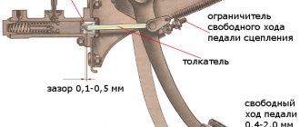
Clutch release pedal and master cylinder diagram
If the clutch is adjusted incorrectly (if the fork is constantly tensioned by the pusher, and the release lever rests on the basket), the clutch may slip during operation.
In this case, the first thing we do is check the clutch adjustment; if this does not help, we change the ferodo disc.
Disk
Adjustment
- In order to align the rod, you need to loosen two nuts 17 and 13.
- Holding the rod, tighten the nut - increase the gap, unscrew - decrease it.
- Use one nut to adjust the gap, and use the other to control the structure in the desired position.
- If necessary, return the spring to its place.
- We check the operation of the clutch when starting off and while driving.
Adjusting the free play
The main task in this procedure is to maintain the free play, that is, the clearance, so that the release bearing does not burn out during constant rotation. Modern baskets already come without a gap, they have a different design, and it is simply not needed there, since it is replaced by a working self-feeding cylinder. But this option does not come from the factory and is not common.
Video
Find useful tips on adjusting the clutch on a classic in the following video:
Malfunctions and what to do
Repair of the KamAZ clutch can be delayed if the machine is regularly maintained.
Load, road surface, driving skills affect the intensity of destructive processes:
- wear of the control drive;
- erasing contacting areas;
- change in the tightness of devices.
To identify malfunctions, before adjusting the clutch drive, the automobile clutch is diagnosed:
- Inspect the drive for leaks, determine the degree of destruction of the pedal springs and fork lever.
- Bring the distance of free movement of the cylinder pusher and the fork axle lever to the recommended parameters.
- Lubricate the balls of the release collet and the clutch fork shaft.
- Determine the liquid level in the main cylinder tank and adjust the amount to normal.
- Tighten the bolts of the pneumatic booster device.
- Change the fluid in the hydraulic drive circuit once a year.
Clutch malfunctions are eliminated as the linings of the drive discs wear out.
If it slips
If the mechanism does not turn on completely, the car accelerates slowly or loses power when climbing the highway, or a burnt rubber smell is heard, then there is an explanation for the problems:
- there is no clearance between the bearing pressing on the basket petals and the stop ring;
- oil has leaked between interacting surfaces;
- friction gaskets have become unusable;
- the clamping springs have lost their shock-absorbing qualities or are broken.
Pros and cons of a single-plate clutch installed on KAMAZ vehicles
- The described KAMAZ clutch has a simple design.
- They compare favorably with their affordable price.
- An additional plus is good heat removal from rubbing pairs, coupled with ensuring reliable operation of the vehicle.
- Relatively light weight and size.
- Good wear resistance.
- Convenience of service.
- Thanks to the low mass of driven parts, gear shifting in a car is easier. This helps to extend the life of gears in the gearbox and reduce repair and maintenance costs.
- The low weight of the components used helps to reduce the impact between the teeth of the gearbox gears during the shifting process, so the drive and driven disks are completely separated. This affects the smoothness of gear shifting, since friction does not occur sharply.