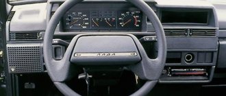
Thanks to the presence of a dashboard (DP), the car owner can know the speed, engine temperature, remaining fuel volume in the tank and much more. The PP, in essence, is the link between the car and its owner. What indicators are located on the instrument panel of the VAZ 2110, how do the devices differ and how to replace the PP? Read about it below.
Description and location of indicators and instruments on the panel
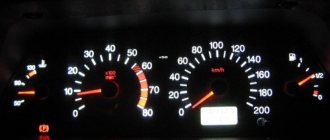
Let's start with a description and designation of the instrument panel icons and symbols in 21102:
- Engine coolant temperature controller; this sensor determines the temperature of the engine as a whole. Thanks to the device, it is possible to promptly detect overheating of the power unit.
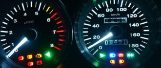
- Tachometer. This controller is designed to display crankshaft speed readings.
- The left turn signal indicator always flashes when the turn is turned on.
- Left right turn signal. Icons numbered 3 and 4 blink synchronously when the light alarm is turned on.
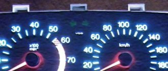
- Speedometer. Thanks to the speedometer, the driver can know how fast his car is moving.
- A controller for the volume of remaining fuel in the tank, which helps the driver navigate when to refuel. If there are about 5-7 liters of fuel left in the tank, a yellow indicator in the form of a gas pump will light up next to the sensor. Do not operate a car with a yellow light on regularly, as this can lead to failure of the fuel pump.
- The gas station indicator, which we described above.
- Light symbol for turning on the side lights.
- The brake system performance symbol appears on the instrument panel when the engine is running if there is not enough brake fluid in the expansion tank. The problem may be due to a leak.
- High beam activation icon.
- Clock setting regulator with switch. Can be used to switch between daily and total mileage data.
- At the bottom of the instrument cluster there is a small screen that displays data on the vehicle's kilometers traveled.
- A light bulb that lights up when the light alarm is activated.
- Check Engine symbol. Its appearance indicates that the control unit has detected a problem with the motor. It is advisable to turn off the power unit and identify the breakdown, which is often caused by the inoperability of auxiliary sensors.
- Clock screen. When the regulator is switched, it may display data on the outside air temperature if such a sensor is installed.
- This instrument lamp indicates a detected malfunction in the battery charging system. The cause may be a loose, worn or broken generator set drive belt. It may also indicate a malfunction of the unit itself, damage to the power circuit and other problems in its operation.
- Handbrake activation icon.
- The symbol in the form of an oil can indicates an insufficient level of engine fluid pressure in the internal combustion engine. When it appears, you need to turn off the car engine and find the cause, which is usually an oil leak from the system.
- The air damper icon is placed only on carburetor engines (the author of the video is the In the Garage channel).
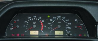
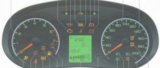
Features of the old and new dashboard
Over the decades of production of the VAZ 2110, the dashboard has undergone certain changes. Therefore, devices can be divided into two groups - devices of the old and new models. It should be noted that these dashboards are not interchangeable, since they have different electrical connection diagrams, as well as designs of the central console in the cars. Moreover, both types of devices are characterized by different shapes, but as for the location of sensors and indicators, in fact it is almost the same.
Over time, devices began to be equipped with backlight brightness controls. In addition, digital odometers (mileage meters) were not used on old-style dashboards; they began to be installed much later. At first, the odometer was mechanical (author - proVAZ-2110 channel).
Connecting the trip computer
The mentioned diagram took into account only one, brown wire leading from the red block to the trip computer, but this is clearly not enough. Therefore, let's see how the pinout occurs here.
- The fuel consumption signal from the electronic control unit is indicated by a green wire;
- Orange leads to terminal “15” in the ignition switch;
- Red and white - to terminal “30” in the ignition switch;
- Black, which is common, goes to ground;
- The speed indicator corresponds to brown;
- The positive terminal of the fuel sensor is green and red;
- Responsible for lighting the dashboard white, it leads to the light control.
Make sure that the board is not damaged, on which, in fact, uninterrupted reading of information from your VAZ 2110 depends, and providing it to you through all those sensors and devices that you always see in front of you.
Probably, hardly anyone will argue with the fact that the VAZ “ten” is not the pinnacle of design thought. However, there is nothing surprising here, because this car was designed back in the last century. At the same time, the compensator, and quite a serious one, in this case is the price. In other words, a certain compromise is proposed - the imperfection of the car in exchange for an acceptable cost. Well, the choice is ultimately made by the car owner himself, deciding whether this option is suitable for him.
Possible malfunctions: signs and causes
What problems can a car owner encounter:
- Some of the light bulbs on the dashboard do not work. If one or more light sources fail, then most likely this is due to burnt-out lamps. The problem is solved by replacing devices.
- The backlight has stopped functioning altogether, while all instruments and indicators light up. Apparently, the reason must be sought in the inoperability of the brightness control itself; it could have broken down. With constant use of this regulator, its connection contact with the on-board network may have come loose, so you need to check the wiring. The reason may also be a blown fuse located in the mounting block.
- The backlight does not turn on, and none of the indicators or sensors work. Perhaps the panel itself was “covered” or the block with the wires connected to the panel was damaged. You need to remove the device and carefully check all circuits.
- The speedometer does not work - the needle does not rise or rises, but very slowly and jerkily. With such a problem, the cause should be sought in the speed sensor, which can be electronic or mechanical. If it is mechanical, then check the condition of the tips that go into the speedometer itself and the gearbox. The end of the cable connected to the speedometer often wears out; you can try to solve the problem by wrapping a piece of food foil around this end. If the sensor is electronic, then you need to check the quality of the contacts.
- Indicators, for example, turn signals or optics, do not turn on. It is necessary to check the functionality of the steering column switches for low and high beam headlights, as well as turns.
- The fuel volume sensor does not function, the needle does not move or has risen all the way and does not fall. In the first case, the reason may lie in the failure of the controller itself, located in the fuel tank. You need to find the sensor and check its functionality. In the second case, the possible cause is a short circuit in the electrical circuit; you will need to test the wiring with a tester.
- The tachometer does not work. Again, the reason must be sought in the crankshaft position sensor - it could have failed, or the contact could have come loose from it. Most often, the reason for the malfunction of the sensors on the device is associated with oxidation of the contacts; they should be checked first.
Features of connecting BC
In conclusion, I would like to dwell in more detail on such a point as installing an on-board computer. In the typical pinout diagram shown just above, there is only one wire leading to it - brown. But for the correct operation of this device, this alone will not be enough. Therefore, here is a complete pinout diagram for connecting the on-board computer:
- Green wire – comes from the electronic control unit, needed to obtain information about fuel consumption.
- Orange – goes to the ignition switch, to terminal 15.
- White-red - in the same place, only to terminal 30.
- The common ground wire is black.
- Brown – needed to take speed data.
- Red-green - to the positive circuit of the fuel level sensor.
- White - leads to the light control, which is responsible for the lamps that illuminate the instrument panel.
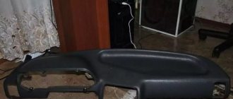
Instructions for replacing the tidy yourself
Instructions for replacing the shield yourself:
- First, you need to turn off the ignition and turn off the power to the Tens electrical network; to do this, open the hood and disconnect the terminal from the battery.
- The switches located on the sides of the tidy are removed.
- Then use a Phillips head screwdriver to unscrew the bolts that secure the device.
- Next, you need to dismantle the mountings of the tidy to the trim. After this, the shield can be easily removed from its seat, and the glass can also be removed.
- The next step is to disconnect all the connectors and connectors connected to the dashboard.
- When the connectors are disconnected, the panel is dismantled. It is repaired or replaced with a new one, the assembly steps are performed in the reverse order (the video was filmed by the channel In the Garage).
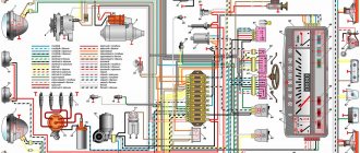
Pinout of the dashboard VAZ2108, 2109, 21099
Connection diagram of the instrument cluster before 1996.
1 — relay-interrupter for the parking brake warning lamp; 2 — tachometer with voltage stabilizer; 3 — instrument cluster lighting lamp; 4 — temperature indicator; 5 — BSK control unit; 6 — fuel level indicator; 7 - resistor 50 Ohm, 5 W; 8 — “CHECK ENGINE” control lamp for the toxicity reduction system; 9 — control lamp for high beam headlights; 10 — side light indicator lamp; 11 — backup warning lamp; 12 - warning lamp for unfastened seat belts; 13 — control lamp for left direction indicators; 14 - resistor 470 Ohm, 0.25 W; 15 - electronic voltmeter; 16 — control lamp for right direction indicators; 17 — warning lamp for emergency oil pressure; 18 — fuel reserve warning lamp; 19 — control lamp for the carburetor air damper; 20 — “CHECK ENGINE” warning lamp for the fuel injection system; 21 - parking brake warning lamp.
Instrument cluster wiring diagram after 1996
1 — tachometer; 2 — instrument cluster lighting lamp; 3 — temperature indicator; 4 — BSK control unit; 5 — fuel level indicator; 6 — “CHECK ENGINE” warning lamp for the toxicity reduction system; 7 — control lamp for high beam headlights; 8 — side light indicator lamp; 9 — backup warning lamp; 10 - warning lamp for unfastened seat belts; 11 — control lamp for left direction indicators; 12 — battery charge indicator lamp; 13 — control lamp for right direction indicators; 14 — warning lamp for emergency oil pressure; 15 — fuel reserve warning lamp; 16 — control lamp for the carburetor air damper; 17 — “CHECK ENGINE” warning lamp for the fuel injection system; 18 — parking brake warning lamp; B1 - 91 kOhm resistor; B2 - resistor 50 Ohm, 5 W.
Ideas for tuning and modifying the shield
How can you improve the tidy in the “Ten”:
- By installing a new trim on the console. This type of tuning is the simplest, since you just need to install a trim on top. However, it will not improve the dashboard itself in any way, only its upper part.
- In the VAZ 2110 you can install a dashboard from Priora; in general, the selection of tuned, ready-to-use dashboards is quite large. When installing a device in 2110 from another car, you will have to partially redo some connectors and connect new devices. But in general there is nothing difficult about this.
- Installation of new scales on sensors. Scales can be downloaded from the Internet, found in a store, or developed independently. The alteration procedure in this case will be more complicated - you will have to remove the shield and disconnect the arrows from the instruments, this will take time. After installing the new scales, the arrows must be correctly installed, otherwise the speedometer and other sensors may malfunction.
- Installation of LED lighting in the tidy. You can simply replace standard light bulbs with LED ones, or purchase a diode strip and solder it into the shield. But keep in mind that if the light bulb fails, it can be replaced without any problems, which cannot be said about the LED strip. If it burns out, you will have to unsolder the tape and install a new one in its place. Although the service life of the LED strip is quite long.
- If you install diode lamps, then you can additionally paint the numbers on the scales, as well as the arrows of the sensors, with fluorescent paint. The fact is that combining these two types of tuning will allow you to achieve a truly high-quality and beautiful result. Under LED lighting, arrows painted with luminescent paint will glow much brighter.
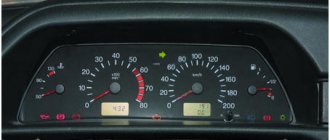
Photo gallery “Tuned devices of VAZ 2110”
Fuel level indicator
The device indicating the fuel filling level of the tank operates in combination with a control sensor; it is installed in the fuel tank. If the lamp shows a resistance of 284-334 ohms on the board, then the indicator needle will be located near the beginning of the scale.
If the sensor reports a resistance identical to the level of 102-136 ohms, then the needle will move to the middle of the scale. If the sensor value is 8-26 ohms, the needle will move to the very end of the scale. If the resistance and the needle level on the scale do not match, then repair of the machine is inevitable.
- Author: ratico19
Rate this article:
- 5
- 4
- 3
- 2
- 1
(2 votes, average: 5 out of 5)
Share with your friends!
Functional
The pinout of this VAZ model is as follows:
- Electronic speedometer;
- Electronic type tachometer;
- Coolant temperature indicator;
- Fuel level indicator in the tank;
- Indicator lamps in the amount of 12 pieces.
This combination is fixed on a special board, in a separate socket using two screws. The panel is removed after unscrewing them. The accuracy of the board is ensured by the printing method of production and installation of this pinout; foil getinax is used for printing.
Indication symbols
As you know, all the lights on the control panel come on when the ignition is turned on, and then, when the engine is already running, most of them go out. But when one remains on or blinks, this cannot but be alarming, because not everyone can immediately figure out what malfunctions this indicates, which of the systems needs urgent repairs.
Let's look at the designations of the instrument panel of the VAZ 2110. You should know that regardless of whether the panel is new or old on your car, the designations are almost the same, but the indicators may be located slightly differently.
Before deciding to upgrade the instrument panel, it is recommended to understand its pinout. Details: https://vazweb.ru/desyatka/elektrooborudovanie/raspinovka-paneli-priborov.html
Car modifications 2114
VAZ-21140. Modification with an 8-valve injection engine VAZ-2111, 1.5 liters and 77 horsepower. Serial production from 2003 to 2007
VAZ-21144. Modification with an 8-valve VAZ-21114 engine, 1.6 liters and 81.6 horsepower. Years of serial production: 2007-2013.
VAZ-211440. Another modification released in 2007, it was equipped with a VAZ-11183 engine with a volume of 1.6 liters and a power of 82 horsepower. The car was discontinued in 2013.
VAZ-211440-24. Released in 2009, a modification with an injection 16-valve VAZ-21124 engine with a volume of 1.6 liters and a power of 89.1 horsepower. Discontinued in 2013.
VAZ-211440-26. Modification with a 16-valve injection engine VAZ-21126, which complies with the Euro-3 environmental standard, with a volume of 1.6 liters and a power of 98 hp. The car was produced from 2010 to 2013.
Where is the mass located?
When operating a car, it is important to know all the places where the mass of the VAZ 2114 engine is located. If a malfunction occurs in this direction, you can quickly detect the source of the problem and eliminate it accordingly
So, where is the mass of the ECU for the VAZ 2114? Let's try to understand this issue.
Where is the mass located on the VAZ 2114:
Battery weight.
Battery weight of VAZ 2114
The negative battery branch consists of branches of wires of two types - thin and thick wire. The battery negative is directed to the motor housing using a thick wire. As a result of poor contact fastening, the charge will be supplied in a small volume, as a result, the starter will not be able to develop sufficient power, and the ECM will therefore fail, because it receives the required mass from the engine.
In order to check the negative charge connections between the battery and the engine, it is necessary to check the reliability of the two nuts, so you first need to loosen the nut from the outside and tighten the nut from the inside, and then screw the nut back on from the outside.
A thin negative wire is connected to the car body next to the battery. It plays the role of an energy source necessary for all consumers equipped in the car. To check, you also need to make sure the degree of tension of the nut both with the body and with the battery terminal.
Weight of ECM VAZ 2114.
Weight of engines VAZ 2114
Samar engines with a volume of 1.5 liters take weight from the engine body, from the mounting plugs, which are located to the right of the cylinder head.
Samar engines with a volume of 1.6 liters, or 1.5 liters equipped with a new type of ECM, take weight from a welded stud. The pin is attached directly to the metal body of the instrument panel near the floor tunnel in the area under the ashtray. When assembled at the manufacturer's factory, the stud is usually poorly secured and painted, as a result, during operation of the machine it can become completely loose, as a result, when the ventilation device is turned on, the electrical voltage of the system will drop, and the following devices will react accordingly: mass air flow sensor, air metering sensor, air pressure sensor.
Instrument panel weight.
Weight of the VAZ 2114 dashboard
In this version, there is a connection between the torpedo harness, the circuit from the mounting relay and fuse block, and the rear harness. This connection is located under the steering shaft mount. If the connection of this mount is not of good quality, problems may arise in the operation of the dashboard readings when the main energy consumers are turned on, for example: turn signals, headlights, etc.
Electric motor heater weight
This ground connection is located under the instrument panel on the left side of the heater housing.
Rewiring. “New sample” panel Part 3.
Hello everyone) A new entry is dedicated to the transition from the AutoDevice (AP) panel with one window 2110-3801010-04 to the new VDO Panel 1118-3801010. The devices are completely different, so the modifications affected primarily the pads.
I took a new 32-pin block from the VAZ 2112 harness; I haven’t seen it on sale separately yet.
It’s not possible to get the contacts out of the green block, unlike the old 13-pin ones. Therefore, the wires were cut with a margin. Then they were soldered to the ends of the wires from the white and red blocks, and covered with heat shrink for insulation.
Information that was used during electrical work: Pinout of old-style VAZ 2110 instrument cluster connectors:
Wiring color coding:
Pinout of new VAZ instrument cluster connectors:
Connecting the instrument block “1118-3801010” (new model) to a VAZ 2110:
To connect the old pads X1, X2 with the new one, you need to connect according to the diagram:
Video “How to install LED lamps in the tidy”
Learn more about how to install diode light bulbs in the control panel yourself from the video below (the author of the video is Alexey Lipatov).
Glowing VDO instrument panel from VAZ 2110
I missed the Latvian illuminated instrument cluster (CI) - I didn’t buy it in the summer of 1999, when it cost 600 rubles. And now the situation with them is quite tense, or more precisely, “... there is no delivery and is not expected.” They say that they are in Tolyatti, but for $80 with a speed sensor. Expensive…
However, in markets and stores there is an abundance of VDO instrument clusters for the VAZ 2110 car, model 2110-3801010-02, which is also installed on the 115 VAZ model. In relation to the “eighth” panel, it has disadvantages:
- Doesn’t fit very well; you’ll have to cut the torpedo visor, otherwise some of the lamps will not be completely visible;
- There is no built-in BSK (on-board control system);
- It is necessary to select a fuel level sensor with the appropriate resistance, otherwise the indicator may be “slightly misaligned”.
Otherwise there are only advantages
- All instruments are more accurate, especially noticeable in the fuel level and coolant temperature sensors;
- The speedometer and tachometer are located in the center, all arrows are controlled by stepper motors - the movement of the arrows is smooth;
- The fuel light doesn't blink like crazy, because... it is ignited by electronics, and not by a contact in the tank;
- The total and daily mileage are displayed on the LCD display - when the car is not started, the mileage is not visible on the instrument panel. Relevant for new cars.
- There is a self-diagnosis mode - you need to turn on the ignition while pressing the reset button for the daily mileage counter.
Another plus: the speedometer cable becomes unnecessary, which often makes various sounds - sometimes it clicks, sometimes it clicks... True, I also had to buy a DS (speed sensor, since I have a carburetor car). The sensor needs to be taken only with an iron pin and a connector identical to the connector of the Hall sensor - it is easier and much cheaper to buy a chip for it.
Connection
Three chips fit the standard CP: white (X1) and red (X2), also one smaller red one (for BSK). Before changing the wires, a bundle of wires from the red block was pulled through the window in the dashboard next to the wires of the white block. Otherwise, you won’t be able to remove the dashboard later—tangled wires won’t allow it.
All wire movements are recorded in tables. If you are not completely sure of success, you can sign each wire by sticking pieces of paper tape on them. As a result, only three wires will remain in their places...
Pinout of the white block (X1) in the instrument cluster of the VAZ 2110
| Designation in 2110 | Compliance in 21083 | |
| 1 | Housing (weight) | Red No. 7 |
| 2 | Tachometer (low voltage input from injector) | Red No. 5 |
| 3 | Tachometer (high voltage input from coil) | Red No. 3 |
| 4 | Const +12V from battery | Red wire of MK connector |
| 5 | Antifreeze sensor | White No. 13 |
| 6 | Fuse F1 | White No. 8 |
| 7 | Throttle valve (“choke”) | Red No. 10 |
| 8 | Motor Controller | Check engine |
| 9 | Fuse F19 + 12V power supply | White No. 4 |
| 10 | Fuse F19 + 12V power supply | White No. 4 |
| 11 | Parking brake | Red No. 8 |
| 12 | Generator output "D" | Matches |
| 13 | Oil pressure sensor | Red No. 12 |
Pinout of the red block (X2) in the instrument cluster of the VAZ 2110
| Designation in 2110 | Compliance in 21083 | |
| 1 | Terminal "W" fuel gauge | Not used (Red No. 11) |
| 2 | Fuse F19 + 12V power supply | Matches |
| 3 | Housing (weight) | Red No. 7 |
| 4 | Instrument lighting switch | Matches |
| 5 | Turn signal RIGHT | Red No. 13 |
| 6 | Turn signal LEFT | White No. 5 |
| 7 | Brake fluid level | Block BSK No. 7 |
| 8 | Motor Controller | Not used |
| 9 | Speed sensor | Pin No. 2 of the speed sensor |
| 10 | Terminal "T" fuel gauge | White No. 11 |
| 11 | Fuse F3 (high beam) | White No. 9 |
| 12 | Hazard switch | Blue wire to the lamp in the button |
| 13 | To terminal “50” of the ignition switch | BSK block No. 2 |
Turning on the brake fluid level light needs a little modification. To do this, you need to disconnect the black wire coming from the brake fluid level sensor from ground and connect it to +12V, for example, to an EPHH unit or switch. Otherwise, the light on the tidy will not work.
Problems with bulk wires
How do problems with ground contacts manifest themselves?
Engine
If the ground wire from the ECM is oxidized or disconnected, this manifests itself in a spontaneous change in operating modes or the car suddenly stalls. Poor contact from the torpedo causes unstable engine operation at idle.
battery
If the contact is broken, the battery charge deteriorates, the starter speed decreases during startup, problems arise in the ECM, because the second ground wire from the battery goes there. To correct the violation, first check the tension of the nuts securing the thick wire to the engine.
To do this, the outer nut is loosened, the inner nut is checked and, if necessary, tightened. The outer nut is then screwed back on. The thin wire is the main conductor of the negative charge. In case of malfunctions, check its condition and the tightness of the nut on the housing, as well as the bolt on the battery terminal.
ECM
Problems may arise due to the lack of a castle washer under the bar and a loose nut connecting the stud and wire in the factory configuration. Over time, due to the resulting backlash between the pin and the wire, voltage surges appear in the channels of several sensors. The result is an uncontrolled increase in engine speed when the fan is turned on.
ECU
Models with 1.5 engine. If the first ground connection from the computer (on the power steering shaft) is in poor contact, when turning on the headlights, direction indicators, sound signal, windshield washer and other consumers, deviations in the temperature and fuel level readings are possible.
Models with 1.6 engine. If the first ground connection from the computer (inside the dashboard) is poorly connected, when the headlights or power windows are turned on, the windshield wiper and washer may start working or the door locking system may work.
If there is poor contact of the second ground terminal from the ECU (on the welded stud), when the side lights, headlights, and radiator fan are turned on, incorrect readings on the temperature and fuel level panel may occur (“jumping” arrows).
FakeHeader
Comments 118
What could it be, I connected it according to the diagram, without a temperature and fuel consumption sensor, and the starter stopped turning? before this, after not touching the wires everything was fine
It’s strange, of course, because the shield in this case is not connected at all with starting the starter. The new ones have immo, there is only an indication. Does the shield itself work “adequately”?
So I think it's strange. The native immo works. The shield works, except for the gasoline needle, but I think that's the problem. Could there be something wrong with the wires not being connected? but also strange
By the way, have you checked the starter circuits directly? Starting with the lock, relay, etc. Does the circuit at least close when turning the key?
Yes, I looked. I changed the relays and visually the wires. Got it. It was necessary to connect together the cut wires of pin 9 of the white block. Oddly enough, the car started. Now it torments me why the tidy resets to zero every time...
It’s clear, it even became interesting - I need to look at the old car diagram to see where the 9th one goes. I usually don’t do this if I have to completely remove the connectors (pads). First, I connect what is necessary for the new option, then, according to the diagram, everything unnecessary (unused) is removed from the harness, and then the remaining but still used wires are connected) Most often, looped masses and power wires, lighting (from the dimensions), and less often signal wires remain. Is it reset, in the sense that all the icons light up, the so-called test mode? Or LCD screen readings?
Everyone does it in their own way, but they still come to the truth. The icons light up when the ignition is turned on, the readings on the screen are updated every time, right? And I noticed that the arrows can hang in one place, and then when I turn the key again, they return. It seems like I’m looking at the diagram, and I didn’t connect pin 20 of the new one correctly, to pin 13 of the red one, but it should have been to pin 4 of the white one...
That's why I asked what exactly was happening. I just wanted to know what happened with the food. Very often they confuse plug-in 12V and constant 12V, which also came to light after the conversation. 20 contact terminal 30 (permanent) 21 contact terminal 15 (after ignition)
Now I have changed it. Everything has become normal. Does not reset. All that remains is to set the arrows
This is good! Set to zero position? The movement of the hands can be checked by turning on the test mode of the shield, it is more convenient.
When I set them to 0, I connected them, and they fell. Then I took it apart again, turned it against the direction of travel, everything works) I’m happy