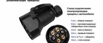
A towbar socket is a device necessary for connecting various signals and ensuring the functionality of the electrics on the trailer: brakes, turn signals, parking lights, license plate lights, etc.
Below we will look at the main types of sockets, talk about connection diagrams and pinout features. We will pay special attention to the purpose of the electronic matching unit and the nuances of connecting the socket.
As an example, we will give the principle of connecting the device to a Chevrolet Niva, a LAV boat trailer, a VAZ-2110 and a number of other vehicles.
Types of trailer sockets
When choosing a socket for a passenger car, pay attention to the types of products.
There are two types on sale (according to the number of cores):
- Seven-core (7 PIN). Designed to output external lighting sources and is used for standard cargo trailers. Such a socket, in turn, can be European or American (they differ in connectors). The peculiarity of the European circuit is that all seven wires are involved in it.
- 13-wire (13 PIN). Unlike the previous type, additional connectors are used here to allow you to connect a caravan trailer and ensure the functionality of all lighting and additional equipment (refrigerator, battery charger, etc.). So, to charge the battery, there is a separate conductor, which goes from the machine’s power source to the towbar socket and is protected by an individual fuse insert.
The 13-wire socket has more functionality and is suitable for many cars from the United States or the EU. But purchasing it will cost a lot, and connecting it will require a higher level of skill.
Sometimes situations occur when the car has a 7-pin socket and the trailer has a 13-pin socket (or vice versa). This is not a problem, thanks to the availability of adapters from 13 to 7 or from 7 to 13.
How to connect a towbar socket
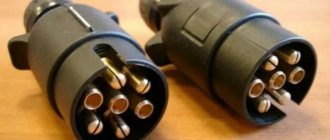
Connecting a towbar socket is not a difficult task, especially if you have such a universal component as a towbar connector. It is convenient when the socket and plug have the appropriate number of connectors. A socket consisting of 7 sockets corresponds to a 7-pin towbar plug, and a socket with 13 sockets corresponds to a 13-pin Euro wiring.
In this case, with the presence of a special connector, connecting the towbar consists of the usual combination of the socket and the corresponding socket. You should first familiarize yourself with the location and appearance of the connected connectors. If they visually match, you can try to attach one to the other.
Connection diagrams (pinout)
When studying the connection diagram for a trailer socket and a car's towbar, it is important to focus on the current GOSTs and rules. They indicate the requirements of government agencies to avoid errors when connecting and operating devices, as well as when checking the electrical connection diagram.
What GOST 9200-76 says
One of the main documents positioning the connection of 7-pin connectors for cars and trucks, as well as tractors, is GOST 9200-76. It was approved and put into operation on January 19, 1976 and is still in effect.
The standard complies with the following ISOs:
- 1185-75.
- 3731-80.
- 1724-80.
- 3732-82.
- 4091-78.
Before the advent of GOST 9200-76, the document GOST 9200-59 was in force, but with the advent of new rules it became invalid.
The following types of sizes are considered here:
- 24 N and 24 S for 24 V voltage;
- 12 N and 12 S for 12 V voltage.
At the request of the consumer, the use of 12N is allowed on car tractors, as well as trailers and semi-trailers with a voltage of 24 V.
Connector Features:
- 24 N is equipped with a large socket for 1 contact and 6 small pins. The inner diameter of the 1st contact must be such as to provide the required disconnection force.
- 24 S also comes with one large 1st contact and 6 smaller ones.
- The 12 N has four sockets (pins one, three, four, and six), as well as three spring-loaded pins—pins two, five, and seven. The diameters of the pins must be such that they fit into the plug sockets and provide the necessary force.
- 12 S provides a special design. This socket is equipped with four sockets (one, three, four and six), one recessed 7th socket (3 mm deeper), as well as a pair of spring pins (second and fifth contacts).
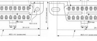
Diagrams and pinouts of 24 N connectors.
Socket, type 24N for rated voltage 24 V
Plug, type 24N for rated voltage 24 V
24N pin assignment
Diagrams and pinouts of 24 S connectors.
GOST 9200-76 pays special attention to technical requirements. In particular, the connector must provide a stable connection at currents up to 40 A. It is important that the pins and sockets do not rotate in their places, and their designation must be applied in a reliable way to ensure good readability.
The permissible temperature rise should not be more than 45 degrees Celsius when the load current is 25% more than the rated one.
Pinout
When connecting the trailer socket and towbar, it is necessary to take into account the subtleties of the pinout. Let's consider each option separately.
7 PIN
7-pin sockets for trailers are used in Russia and Europe. Type - 12 N, ISO 1724.
The designation of the legs is as follows:
- Left turn signal (L). Yellow, 1.5 sq. mm.
- Rear fog lights or +12 V (54G). Blue, 1.5 sq. mm.
- Grounding (“minus”) White/gray, 2.5 sq. mm.
- Turn signal right (R). Green, 1.5 sq. mm.
- Lamp for illuminating the license plate and marker on the right (58R). Red, 1.5 sq. mm.
- Brakes - stop light (54). Red, 1.5 sq. mm.
- Left dimension (58L). Black, 1.5 sq. mm.
Simplified diagram.
In the case of the American version of the 7 PIN socket, the placement of the contacts is slightly different. Here the reverse contact connector has been changed, and there is no section on left and right dimensions. In a number of cars from the USA, the dimensions and STOP signals, which run on the same wire, are not separated.
Alternatively, you can assemble a “Russian” circuit. Its peculiarity is that there may be no wire on the PTF, or there will be only one, connected to the 7th pin of the plug. In this case, the 5th contact is not used or is short-circuited by the 7th.
One example of a 7-pin device is the ATE-05 metal socket from the manufacturer Airline. This is the most durable product for a towbar without an elastic boot.
13 PIN
When choosing a 13-pin socket (ISO 11446), the number of connectors is larger, so you need to be more careful when connecting.
Let's look at the main elements:
- Left turn signal (1/L). Yellow, 1.5 sq. mm.
- Rear fog lamp (2). Blue, 1.5 sq. mm.
- Ground connector for terminals one through eight (3/31). White, 2.5 sq. mm.
- Right turn signal (4/R). Green, 1.5 sq. mm.
- Right side marker and license plate light (5/58-R). Brown, 1.5 sq. mm.
- STOP signal lamp (6/54). Red, 1.5 sq. mm.
- Dimensions on the left and license plate illumination (7/58-L). Black, 1.5 sq. mm.
- Reverse lamp (8). Pink, 1.5 sq. mm.
- Constant voltage at 12 V and 35 A (9). Orange, 2.5 sq. mm.
- Voltage 12 V and 35 A (supplied after turning the key in the ignition), (10). Gray, 2.5 sq. mm.
- "Mass" (11). Black and white, 2.5 sq. mm.
- Signal conductor, reserve (12). Light grey, 1.5 sq. mm.
- Ground for the ninth terminal (13). Red-white, 2.5 sq. mm.
Having before your eyes the pinout of the trailer and towbar sockets, you can easily make connections and carry out an electrical inspection (in case of a malfunction).
In Europe, 7-pin (ISO-1724) and 13-pin (ISO-11446) connectors are in demand. As you can see from the pinout above, the 13-pin version gives more options and has better protection against water and dirt.
The connectors work on 12V systems, but there may be exceptions for the 7-pin connector. They often operate on 6 and 24 V. Thus, cars and trailers with 6-pin systems can use a 7-5 pin connector.
Self-installation
You can install the electrical system of the tow bar yourself. This will take about 2 hours. The electrics have a simple diagram for connecting the trailer plug to the socket. The connector must provide an easy and reliable connection of electrical wiring.
In order to install a socket, you need:
- Open the trunk of the car and remove the plastic or felt trim. It is better to dismantle the fastening clips with a spatula-shaped puller with a slot. In this case, the clips will remain intact and there will be no need to buy new ones.
- Inspect the rear of the luggage compartment. Where the bumper is attached, there should be rubber plugs through which the wire passes that powers the license plate illumination. Through this rubber band, you need to insert a bundle of wires into the trunk to connect the towbar socket.
- Inspect the tire going to the taillights. Divide the bundle into individual wires.
- Strip no more than 1 cm of insulation on each wire. You need to connect the wires from the outlet to the exposed areas. The connection is best made using crimp locks for quick splicing of wires. It's better quality than twisting.
- Secure the socket to its bracket using bolts.
- Check that the connection is correct. To do this, you need to hook the trailer to the towbar and check the operation of the light alarm.
If the trailer's electrics work, you can install the trim.
Why do you need an electronic matching unit?
Not in all cases it is possible to simply connect the sockets of the towbar and trailer. If the machine has complex electronics, a matching unit will be required.
Its use allows you to avoid errors when testing the operation of lighting equipment and vehicle electrical systems.
In addition, the matching unit is an invariable thing when it is necessary to transmit a signal using a multiplex bus.
The connection diagram is as follows:
- Signals from the car are sent to the matching unit.
- The latter processes the information.
- If there are no conflicts, the signal is transmitted to the trailer of the car or truck.
For correct operation, the unit must be connected to the battery and the wires must be connected correctly (taking into account the pinout).
The connection diagram is shown below.
About installation methods when connecting a tow hitch
The presence of electronics in the vehicle control system allows the use of an electronic coordination unit in the installation of the electrical system for signaling and trailer control. It will monitor and test control signals through a multiplex program.
If the current in the circuits increases, the device will generate an error in signal transmission. Installation and connection to the connector on the tow mechanism is carried out according to a special program with the connection of a matching device in the circuits.
During installation, it is necessary to use a device in the circuits of the machine that will transmit control signals through the matching unit to the towed mechanism, and not through the detachable part in the trailer.
What is needed to connect
Before connecting the trailer socket, you need to prepare and buy the necessary material in advance.
The package includes the following equipment:
- Socket cover for tow bar. Please note that there is a cover equipped with a rubber seal. When purchasing, inspect the product for the fit of all casing elements and for the absence of loose housing or contact connections. Pay special attention to the condition of the threaded connection and the fastening of screws to the terminals.
- Wire (one core) with a cross-section of 1.5 sq. mm or more. When purchasing, check the possibility of using it in the electrical wiring of a vehicle.
- Corrugation made of metal or polypropylene. Used to insulate wire harnesses and protect against mechanical damage. The average length is up to 2.5-3.0 meters. Immediately take 20-30 plastic clamps to secure the harnesses.
- Connecting blocks. When choosing, give preference to a model with sockets in which fuses can be installed.
- Tools: set of wrenches, drills and bits, screwdrivers, soldering iron, electrical tape.
The specified equipment is usually sufficient for installation work. If something is missing, the scarce elements can be purchased separately.
conclusions
Now all that remains is to properly connect the trailer to the car and enjoy the result. If you notice a new type of socket or a complete disappearance of the models shown here from the shelves, please let us know. And don't forget to share the article with your friends!
Sources
- https://pricep-vlg.ru/legkovye-pricepy/podklyuchenie-pritsepa/
- https://PricepInfo.ru/spravka/raspinovka-rozetki-farkopa/
- https://AutoTopik.ru/jelektrika/kak-podkljuchit-rozetku-pricepa.html
- https://TechAutoPort.ru/nesuschaya-sistema/dopolnitelnoe-osnaschenie/rozetka-farkopa.html
- https://DriverTip.ru/zhizn/pravilnoe-podkljuchenie-rozetki-pricepa-legkovogo-avtomobilja.html
- https://odinelectric.ru/wiring/rozetki-i-vyklyuchateli/shema-rozetki-pritsepa
- https://pricepclub.ru/remont-i-obsluzhivanie/podklyuchenie-rozetki-pritsepa-legkovogo-avtomobilya
- https://avtoshark.com/article/repairs/electronics-repairs/podklyuchenie-rozetki-farkopa-k-avtomobilyu/
- https://www.asutpp.ru/raspinovka-rozetki-farkopa-pricepa.html
Features of connecting trailers Skif-M1, Skif-M2, MZSA and others
When connecting SKIF trailers, you need to be careful, because the pinout in them is somewhat different from the 7-pin circuit according to GOST 9276 and ISO 1724.
Thus, on the second terminal of the Skif-M1, produced from 1981 to 1987, and Skif-M2, produced from 1987 to 1993, the “plus” of the battery is located, and not the rear fog lamp.
Skif-M trailer electrical diagram
Electrical diagram of the Skif-M1 trailer
Electrical diagram of the Skif-M2 trailer
In addition, on MZSA trailers, the dimensions are connected only to the 7th contact. This is done for convenience, so that if necessary you can connect to an old domestic car.
The presence of a “+” battery is a big plus when camping, because it can be used to connect lighting. The designation of the contact group has also changed. Instead of the usual Arabic numerals, Roman numerals are given here.
If we talk about earlier versions of Skif-M, they have more differences.
The following scheme was used here:
- I—STOP signal;
- II - left turn signal;
- III — turn signal indicator light;
- IV - right turn signal;
- V - “plus” of the battery;
- VI — rear dimensions and license plate lights;
- M is mass.
The circuit provides a matching block that relieves the car's turn signal relay.
To operate this element, constant power is required, supplied through the fifth contact from the battery through the outlet.
The old connectors did not separate the side light contacts and they were supplied only through the seventh contact, and the second was considered a spare one.
A lamp was provided there that allowed you to monitor the operation of the trailer and its turn signals.
When connecting an old trailer to a modern type socket, the turn signal on the trailer hitch will only flash when the lights are on. In addition, the fog light (on some models) and the warning light on the dashboard may flash.
In the case of MZSA trailers, nothing comes of the fifth signal. Therefore, if after connection the lights on the tow hitch do not light up, the reason, as a rule, is that the signal is output to the fifth contact, but there will be no signal on the seventh.
A number of trailer manufacturers in the Russian Federation, when installing a reversing lamp, connect it to the fifth terminal, leaving the dimensions with the seventh contact connection.
American connecting chips
Many American standards differ from European ones, and trailer hitch socket pinouts are no exception. Here are two types for your reference: 7 and 4 pin connectors.
The 7-pin socket, used in the HOPKINS model range, as well as in other cars (Fig. 8), differs from the European standard practically only in design, which allows, if necessary, replacement with a European analogue.
American 7-pin towbar socket
Designations:
- Connecting side lights.
- +12 V.
- Starboard turning lights.
- Brake light control.
- Weight.
- Turning lights on the left side.
- Reverse signal.
Now let's consider a more complex option - a 4-pin connector (see Fig. 9). If you try to replace it with a European 7-pin socket, problems will arise.
4 pin connector
Designations:
- Weight.
- Control of side lights.
- Left side turn signal and brake light control.
- Starboard turn signal and brake light control.
As you can see, the difficulty is due to the fact that the turn signals and brake lights are controlled along the same line. There are two ways to solve the problem:
- Not entirely correct, but the easiest way: connect directly to the stops and turn signals. Note that in some cars the wiring may not withstand the additional load, so it is better to solve the problem in another way.
- This option is somewhat more complicated, but more correct: you need to completely extend the wiring under the European connector. For example, in a Chevrolet Tahoe, to do this you need to remove the instrument panel, find wires with separate signals for the turn signals and brake lights, connect to them by stretching the electrical wires from the towbar socket through the entire interior of the car. You can make the task a little easier if you take the signal for the brake lights from the rear fender; it is displayed there on almost all cars. In this case, you only need to pull two wires.
LAV boat trailer pinout
Of particular interest is the pinout of contacts in LAV brand trailers. Let's highlight the features of contacts:
- Left turn signal.
- Rear PTF.
- Weight.
- Right turn signal.
- Reversing lamp.
- STOP signal.
- Side and contour lights, room lighting.
Knowing the features of the contact group will help you accurately connect the trailer and towbar socket.
Pinout of 7 pin socket
Below is a drawing showing the wiring of a 7-pin connector (socket and plug). The typical colors of wires for Russian-assembled cars are indicated (color deviations are possible). In European machines, not all contacts on the connector may be used.
Pinout of the 7-pin towbar socket (A) and the corresponding trailer plug (B)
Explanation of the picture:
- Left side turn signal control signal.
- PTF connection (in foreign cars the contact may not be used).
- Weight.
- Starboard turn signal control signal.
- Side lights on the left side.
- Brake light control.
- Side lights on the starboard side
Currently, the 7-pin connector is practically not used in modern foreign cars; 13-pin sockets are installed there. If the trailer has an old type plug, you can connect it to the new Euro connector using a special adapter, which is much easier than changing the connector.
Adapter from 7 to 13 pins
Connecting a VAZ 2110 trailer socket
The VAZ 2110 uses a trailer socket made according to the 12 N, ISO 1724 standard.
There are seven contacts here: two turn signals (first and fourth), fog light (second), ground (third), rear lights and right side lights (fifth), brake light (sixth) and left side lights (seventh).
As in previous cases, wires with a cross-section of 1.5 square meters are used for all contacts. mm, except for the “ground”, which goes to 2.5 square meters. mm.
Pinout of 15 pin connector
- 1 – yellow – left turn signal;
- 2 – green – right turn signal;
- 3 – blue – signal from rear fog lights;
- 4 – white – negative contact;
- 5 – black – left hand signal;
- 6 – brown – right-hand side signal;
- 7 – red – brake light signal;
- 8 – pink – reverse signal;
- 9 – orange – positive contact;
- 10 – gray – brake pad signal;
- 11 – black and white – spring brake signal;
- 12 – white-blue – drawbridge signal;
- 13 – white-red – general contact;
- 14 – white-green – Can-H;
- 15 – white-brown – Can-L.
Niva Chevrolet
When connecting a trailer socket to a Niva Chevrolet, you can use a wiring harness with a trailer hitch (tow hitch) and European accessories 0183 for the specified Avato model. Article - 00001-75045552-00-0.
In addition, this harness is suitable for connecting trailers of other cars with a 7-pin connector, avoiding the use of a bundle of wires with five + two wires.
Important information
The definition of a connector can be described as a combination of plugs and sockets that are connected after the trailer is attached to the hitch.
Here it is important to pay attention to who is the manufacturer of the towing device and the trailer itself. In some cases, the number of contacts they have is different. Our standard pinout includes 7 contacts. This is a European and domestic manufacturing principle. But if you have an American car in front of you, be so kind as to understand the 13-pin connector. It is also important that the contacts on plugs and sockets are counted differently.
If you need to connect different types of trailers and vehicles, you will need to use a special connection block or adapter. Alternatively, you can make adjustments to the pinout. But this will require deeper knowledge of auto electrics, as well as a detailed study of the design of the car itself.
Connecting a trailer socket to a KamAZ truck
Owners of KAMAZ trucks often ask what type of socket can be used for a trailer.
The main option is a plug device type PS 325-100 for 24 V. The product is designed to transmit electrical signals to side lights, brake lights, turn signals and other elements. They come with 7 and 15 cores.
In this case, 7-core models are conventionally divided into two types - N and S. The first type is very similar to the other models, and the S-type has the appearance of an empty tube.
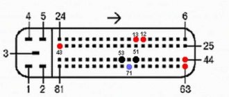
Pinout:
- Mass (Part 4), white.
- Left size (G.52), black.
- Turn signal on the left (K.75), yellow.
- Brakes (3.57), red.
- Turn signal on the right (P.74), green.
- Right gauge (Kch. 52), brown.
- Not involved. You can connect a reverse gear or a portable lamp. Blue.
As an analogue, you can use a 24 V socket manufactured by BAAZ). Its pinout is the same, only the manufacturer is different.
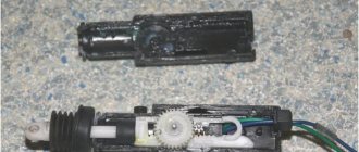
When choosing the original PS 325, pay attention to the following points:
- When turning the product over, the lid should not open. It is optimal if it is well spring-loaded and opens only with force from the user.
- The pins inside should not dangle.
- In the fake, the holes at the base are very small. You can check this using a special wire crimper.
- Pay attention to the quality of the internal thread and material. It is very difficult to screw a screw into a fake socket. In addition, the product itself is made of aluminum.
Knowing these points allows you to distinguish a fake from an original and avoid wasting money.