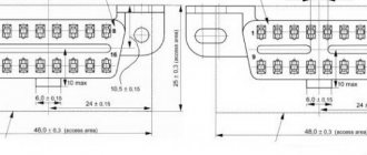
This contact assignment is suitable for Electronic Control Units BOSCH M7.9.7 / January 7.2, used on LADA (VAZ) 2111, 2114, 2109 and others, on which engines 21114 and 21124 were installed.
| № | 8 valve engine (21114) | 16 valve engine (21124) | Car with two oxygen sensors (Euro 3) |
| 1 | Second cylinder ignition coil control output | ||
| 2 | Ignition coil control output for cylinders 2-3 | Third cylinder ignition coil control output | |
| 3 | Ignition coil weight | ||
| 4 | Fourth cylinder ignition coil control output | ||
| 5 | Ignition coil control output for cylinders 1-4 | Ignition coil control output of the first cylinder | |
| 6 | Injector pulse of the second cylinder | ||
| 7 | Injector pulse of the third cylinder | ||
| 8 | Tachometer output | ||
| 9 | Not used | ||
| 10 | Fuel consumption signal | ||
| 11 | Not used | ||
| 12 | Terminal 30. Constant power supply from battery | ||
| 13 | Terminal 15. Power from the ignition switch | ||
| 14 | Main relay control output | ||
| 15 | Crankshaft sensor input (A) | ||
| 16 | Throttle position sensor signal input (C) | ||
| 17 | Throttle sensor ground (B) | Weight TPS, Rough Road Sensor | |
| 18 | Oxygen sensor 1 signal input (A) | ||
| 19 | Knock sensor input | ||
| 20 | Knock sensor weight | ||
| 21 | Not used | ||
| 22 | Not used | ||
| 23 | Not used | ||
| 24 | Not used | ||
| 25 | Only on Bosch - high current output, reserve | ||
| 26 | Only on Bosch - high current output, reserve | ||
| 27 | Injector pulse of the first cylinder | ||
| 28 | Not used | Second oxygen sensor heater control output | |
| 29 | Not used | Engine cooling fan control output | |
| 30 | Not used | ||
| 31 | Check lamp | ||
| 32 | Power supply (+5V) throttle position sensor | Power supply for TPS and rough road sensor | |
| 33 | Power supply (+5V) of the Mass Air Flow Sensor | ||
| 34 | DPKV input, contact “B” | ||
| 35 | Coolant Temperature Sensor Ground | Weight of Coolant Temperature Sensor, Mass Air Flow Sensor and two Oxygen Sensors | |
| 36 | Mass Air Flow Sensor Weight | ||
| 37 | Signal input from Mass Air Flow Sensor | ||
| 38 | Not used | ||
| 39 | Signal input from Coolant Temperature Sensor | ||
| 40 | Signal input from intake air temperature sensor | ||
| 41 | Not used | ||
| 42 | Not used | Signal input from Rough Road Sensor | |
| 43 | Not used | ||
| 44 | +12V power input after main relay | ||
| 45 | Phase sensor power output (Camshaft sensor) | ||
| 46 | Canister purge valve control output | ||
| 47 | Fourth cylinder injector pulse | ||
| 48 | Oxygen sensor heater control output | ||
| 49 | Not used | ||
| 50 | Controlling the additional starter relay | ||
| 51 | ECU weight | ||
| 52 | Not used | ||
| 53 | ECU weight | ||
| 54 | Not used | ||
| 55 | Not used | Second oxygen sensor signal input | |
| 56 | Not used | ||
| 57 | Input for encoding calibration data options. The controller memory can store two options for calibration data, one of which is selected by connecting or not connecting this contact to ground in the wiring harness. In the absence of a connection to ground, this contact is supplied with on-board voltage through the internal resistor of the controller. | ||
| 58 | Not used | ||
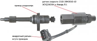
| 59 | Speed Sensor Signal | ||
| 60 | Not used | ||
| 61 | Mass of Output Cascades | ||
| 62 | Not used | ||
| 63 | +12V power input after main relay | ||
| 64 | Contact "D" of the Idle Air Controller | ||
| 65 | Idle Air Control Terminal "C" | ||
| 66 | Idle Air Control Terminal "B" | ||
| 67 | Idle Air Control Terminal "A" | ||
| 68 | Output to control the engine cooling fan relay | ||
| 69 | Air conditioner relay control output | ||
| 70 | Output for controlling the fuel pump relay | ||
| 71 | K‑Line (Diagnostic line) | ||
| 72 | Not used | ||
| 73 | Not used | ||
| 74 | Not used | ||
| 75 | Air conditioner request signal | ||
| 76 | Request to turn on power steering | ||
| 77 | Not used | ||
| 78 | Not used | ||
| 79 | Phase sensor signal input | ||
| 80 | Weight of output stages | ||
| 81 | Not used | ||
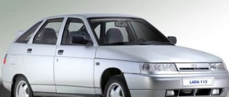
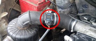
Where is the VAZ 2114 ECU located?
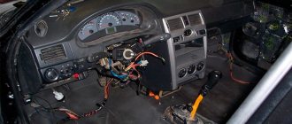
The block is located in the dashboard, directly under the tidy. To replace or dismantle, you need to unscrew the screws and remove the panel from the side, on the passenger side. Through the resulting hole you can see the ECU housing - it is installed inside a steel retainer.
To remove the electronic control unit, you need to unscrew the bolt and carefully pull out the housing, grasping the latch. Of course, it is necessary to turn off the power from the on-board network, otherwise expensive equipment can be damaged. A short circuit is the enemy of any electrical appliance, so be careful. It is advisable not only to remove ground from the battery, but also to disconnect the positive wire.
Work sequence
Diagnostic connector pinout
Before dismantling the device, you should disconnect the negative terminal from the car battery:
The vehicle must be placed on a flat surface, without slopes, and the parking brake must be set. The following stages of work are performed inside the car
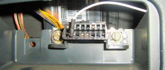
You will need to carefully unplug the wire connector from the control box, but before doing so, you should unplug the latch. When you get directly to the powertrain control controller, using a wrench you will need to unscrew the two nuts that secure the module to the bar. After these nuts are unscrewed, you will need to move the bar itself slightly to the right side, this will allow it to be released from engagement. After completing these steps, the control controller can be dismantled. If you are replacing a device, then if it breaks down, you should replace the module with a similar one that was installed
That is, if you had a January 7.2 ECU, then the same module is installed. If the unit is subject to repair, it should be repaired and then reinstalled. The installation procedure is performed in the same way, only in reverse order.
Do not repair the control unit if you have never had to deal with such a task before!
How does the ECU work?
At the heart is a microprocessor, which is responsible for the normal functioning of all key devices. On a VAZ 2114 car, the ECU collects data from sensors:
- Vehicle speed.
- Detonations.
- Lambda probe.
- DPKV.
- Air flow.
- TPDZ.
- Phases of injection of the air-fuel mixture.
- Coolant temperatures.
These are reading devices that collect information about the operation of an internal combustion engine. Why does he collect it? It is correct to divide and conquer by the following actuators:
- Fuel supply system (pump, injectors).
- Ignition system.
- Adsorber.
- Ventilation.
- Idle air control (yes, yes, this is not a sensor, but an actuator, no need to be confused).
- Automatic diagnostics.
The block diagram of the electronic control unit on the VAZ 2114 consists of three cascades, each of which has its own memory modules:
- A RAM unit (random access memory) is a system that has short-term memory. It stores all information about errors that occurred during operation during the current engine start. When the ignition is turned off (and the computer is de-energized), all memory is cleared and filled again the next time it starts.
- PROM is a programmable read-only memory device. This is the block in which the fuel map (firmware) of the electronic control unit is stored. It also permanently stores information about all system calibration results. And most importantly, this memory contains the algorithm of the internal combustion engine control system. This memory is permanent and is not erased even if the on-board network is completely disconnected. It is this block that is programmed when the “firmware” procedure is performed to improve the characteristics of the VAZ 2114 car.
- And the last block is the ERPZU. The memory unit is necessary to ensure the normal operation of the anti-theft system on the car. It stores passwords and encodings. Starting the engine is possible only if the data exchanged between the immobilizer and the EEPROM matches.
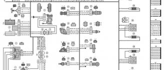
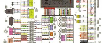
Electrical diagram of the ECM of a VAZ-21104 with controller 21124-1411020-30/31/32
List of elements of the electrical connection diagram of the ECM EURO-2 M7.9.7 vehicle 21104:
1 — block of the ignition coil wiring harness to the ignition system harness; 2 — block of the ignition system harness to the ignition coil wiring harness; 3 — ignition coils; 4 — immobilizer warning sensor; 5 — immobilizer control unit; 6 — spark plugs; 7 — nozzles; 8 — diagnostic block; 9 — block of the ignition system harness to the ABS cabin group harness; 10 - controller; 11 — electric fuel pump; 12 — block of the ignition system harness to the fuel level sensor harness; 13 — block of the fuel level sensor harness to the ignition system harness; 14 — block of the ignition system harness to the injector harness; 15 — injector harness block to the ignition system harness; 16 — block of the ignition system harness to the side door harness; 17 — speed sensor; 18 — idle speed regulator; 19 — throttle position sensor; 20 — coolant temperature sensor; 21 — mass air flow sensor; 22 — oil pressure warning lamp sensor; 23 - phase sensor; 24 — oxygen sensor; 25 — crankshaft position sensor; 26 — knock sensor; 27 — solenoid valve for purge of the adsorber; 28 — oil level sensor; 29 — coolant temperature indicator sensor; 30 — block of the ignition system harness to the instrument panel harness; 31 — block of the instrument panel harness to the ignition system harness; 32 — ignition relay; 33 - ignition relay fuse; 34 — fuse for the electric fuel pump power supply circuit; 35 — electric fuel pump relay; 36 — electric fan relay; 37 — controller power supply fuse; 38 — ignition system harness block to the air conditioner connector; 39 — instrument cluster; 40 — ignition switch; 41 — electric fan of the cooling system; 42 — on-board control system unit; 43 — starter relay; 44 — contacts of the 8-terminal blocks of the instrument panel harness and the front harness; 45 — contacts of the 21-terminal blocks of the instrument panel harness and the rear harness; 46 — trip computer; 47 - diagnostic connector.
A - to the “plus” terminal of the battery; B1 — grounding point of the ignition coil wiring harness; B2 — grounding point of the fuel level sensor harness; B3, B4 - grounding points of the ignition system harness; C - to the starter; D - to the driver's door interior lamp switch.
The wires in this diagram have a letter designation of color and a designation of the number of the circuit element to which this wire is connected. The number of the block contact is indicated through the fraction. 01/14/2005
Repair and diagnostics of control units
The VAZ 2114 controller often breaks down. The system has a self-diagnosis function - the ECU queries all components and issues a conclusion about their suitability for operation. If any element fails, the “Check Engine” lamp will light up on the dashboard. It is possible to find out which sensor or actuator has failed only with the help of special diagnostic equipment. Even with the help of the famous OBD-Scan ELM-327, loved by many for its ease of use, you can read all engine operating parameters, find the error, eliminate it and delete it from the memory of the VAZ 2114 ECU.
Of course, it is wrong to simply delete errors. Be careful, because malfunctions don’t just appear. A good example is that a friend’s oxygen sensor broke down. And every other day he cuts down the mistake so that “it doesn’t become an eyesore.” But the reason lies in a faulty lambda. But what to do if the ECU does not want to respond to the scanner at all? Then check the following:
- Is there any mechanical damage to the housing, including oxidation and corrosion?
- The fuse is working properly, there is voltage and a connection to the power supply minus.
- Is the device overheating?
It is unlikely that you will be able to repair the control unit yourself; the work is too delicate. You can only replace it with a new one with your own hands.
Video “No spark and blown fuse - repairing the ECU”
What to do if there is no spark and the fuses are constantly blowing - the video below shows the process of repairing the control controller in a garage (the author of the video is the Auto Practice channel).
I came across an article by McSystem. Actually, here it is below
In January - about Januarys. Again and in detail about the ECM-ECU masses
One of the rather serious problems affecting the stable operation of engines controlled by the January ECU (7.2, 7.2+, M73, 7.9.7) is the “mass problem” of the ECM. Moreover, the point is not so much in bad (or uncrimped) contacts and their fastenings, but rather in the rather incorrect wiring of the ECM harness itself. And the solution is not in “pulling a fancy cable (KG-25 or 50)” to the ECU. Therefore, this material will be devoted to a technically competent approach to solving this problem. What is described below is a kind of compilation, or an attempt to “chew” what has been published more than once, in particular on ChipTuner.ru, and to convey to readers the specifics of solving this problem. The articles by I.N. turned out to be the most complete and informative. Skrydlova, (aka Aktuator) “About the masses”, “MASS: AN UNEXHAUSTABLE SOURCE OF GLITCHES” “ONCE AGAIN ABOUT THE MASSES” Oleg Bratkov. Many years ago, having read and comprehended what was written, I implemented it on my typewriter. I completely agree with the conclusion of the author (aka Aktuator): “All the assurances of AVTOVAZ OJSC about improving the quality of electrical connections in manufactured vehicles are not worth a penny. In most cases, it is possible to achieve normal operation of the engine under the control of the ECM I 7.9.7 and January 7.2 only by carrying out additional, and not accepted by the manufacturer as a warranty, work to change the electrical circuit of the car.”
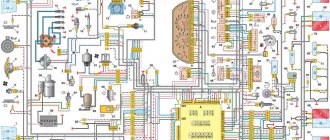
So, on to the topic! Classic ECM 21124 with ECU January 7.2(+) or M7.9.7 Electrical connection diagram of ECM EURO-2 M7.9.7, January 7.2 LADA 2110 with engine 21124. 21124-1411020-30, 21124-1411020-31.32
Fig. 1 ECM 21124 January 7.2, M7.9.7 Noticed, often described and characteristic problems - unstable idle speed, freezing speed, “jerking” of the engine at start and operation of the cooling fan, unreasonable jumps in the electrical parameters of the ECM during diagnostics. And this is not the entire list. And the whole problem is a rather incorrect wiring of the harness masses, not in relation to the body, but to the ECU. Therefore, in this article you will not see recommendations for tightening the “hoses” of additional mass to the ECU, due to its complete uselessness. This is not a newfangled “razmasovka” or “razminusovka”... Don’t get your hopes up!
The main idea voiced by the authors is that the wiring of the power lines of the ECU and fan and low-current sensor masses is fundamentally incorrect. Rice. 12
Fig.2 Ground connections of the ECM. S6, S7, S8
The sensors must be connected to the ground bus of the ECU board and not have contact with the body! There should be no flow of pulsed and direct currents of the ECU and IM in the sensor mass circuit. And the ECU is securely connected to the body. The rationale is to eliminate the influence of ECU currents (pulse and constant) and fan current on the reliability of sensor readings. Classic approach with data collection and processing systems! But not from AvtoVAZ designers, as usual... Now, in order
Fig. 3 Masses according to AvtoVAZ, or how not to do it
1. The ECU masses are combined into three crimps S6, S7, S8, which are combined with each other and TWO bends are already made from them to the body studs B3, B4. 2. A switched minus fan with a rated current of 12A is connected to S6, and at the peak at start - all 20A! ! ! Which in itself is terrible! 3. All this is connected (screwed) to the ECU bracket, which in turn is very flimsily connected to the body. The engine ECM consists of sensors and actuators (AM). Sensors can be easily divided into analog and discrete. Analogue – mass air flow sensor, air pressure sensor, diesel sensor, DD. The output signal of these sensors is a voltage in a certain small range, usually 0 - 5V. For this group, any (even small) interference has a serious impact on the result. Discrete ones - DC (to some approximation), DF, DS (Speed Sensor) - are less critical to interference, because the output signal has two fixed levels high and low, and intermediate levels are not interesting to the ECU. Actuators - ignition coils, injectors, canister valve, DC heating, IAC, relays and other sources of large pulsed and direct currents along the negative (mass) bus of the ECU. To understand what the developers were up to, let’s look at the diagram in Fig. 3 – this is a fragment of the main ECM diagram in expanded form. It immediately catches your eye - the masses of the most sensitive and responsible sensors, mass air flow sensors and diesel fuel sensors, are wired, although there are separate pins for them, 36 and 35, respectively. For what? Silence in response! S6-S7-S8 are connected by jumpers, which makes the situation even worse.
Types of ECU VAZ 2114
The car was produced for more than 10 years, constantly improved, the characteristics became better and better. Of course, this was achieved through the use of new motors, sensors, and actuators. And most importantly, thanks to the installation of control units, whose operating speed is much higher (you have all heard about the frequency of processors; it is on this parameter that the characteristics of internal combustion engines depend today).
January-4 and GM-09
Until 2003, these electronic units were installed. They had a very wide range of models, the main difference between them was the presence or absence of a resonant-type knock sensor. The price of a VAZ 2114 ECU of the “January-4” type is no more than 6,000 rubles. The list of modifications is given in the table:
| 21114-1411020-22 | January-4, without oxygen sensor, RSO, 1st production version |
| 21114-1411020-22 | January-4, without oxygen sensor, RSO, 2nd production version |
| 21114-1411020-22 | January-4, without oxygen sensor, RSO, 3rd serial version |
| 21114-1411020-22 | January-4, without oxygen sensor, RSO, 4th production version |
| 21114-1411020-20 | GM,GM_EFI-4,2111 with oxygen sensor, USA-83 |
| 21114-1411020-21 | GM,GM_EFI-4,2111 with oxygen sensor, EURO-2 |
| 21114-1411020-10 | GM,GM_EFI-4,2111 with oxygen sensor |
| 21114-1411020-20h | GM, RSO |
Electronic control units ITELMA 5.1, January 5.1.Х, Bosch M1.5.4
These ECUs belong to the next generation, they were successfully used on cars of models 2113 and 2115. If you are the owner of a VAZ 2114 car, which was released in 2013 or later, then the method of injection of the fuel-air mixture can distinguish it from its relatives: phased, pair-parallel or simultaneous. In general, all three ECUs (January, Bosch and Itelma) are complete analogues of each other. Modifications “January” and ITELMA:
| 21114-1411020-71 | January-5.1.1, without sensor acid, CO |
| 21114-1411020-71 | January-5.1.1, without sensor acid, CO |
| 21114-1411020-71 | January-5.1.1, without sensor acid, CO |
| 21114-1411020-71 | January-5.1.1, without sensor acid, CO |
| 21114-1411020-71 | January-5.1.1, without sensor acid, CO |
| 21114-1411020-72 | ITELMA, without sensor acid, CO |
| 21114-1411020-72 | ITELMA, without sensor acid, CO |
| 21114-1411020-72 | ITELMA, without sensor acid, CO |
| 21114-1411020-72 | ITELMA, without sensor acid, CO |
Modifications of BOSCH electronic control units:
| 21114-1411020 | Without sensor acid, RSO |
| 21114-1411020 | Without sensor, acid, CO (registered with CO scanner) |
| 21114-1411020-70 | BOSCH, without sensor acid, RSO |
| 21114-1411020-70 | BOSCH, without sensor acid, RSO |
On VAZ 2114 cars produced in 2003-2007, you can most often find “January-5.1.1”. The price of such a block ranges from 7000-8000 rubles. On export versions of cars, as a rule, a Bosch brain was installed, the price of which was the same.
"January-7.2", Bosch M-7.9.7
The modification on the seventh of January depends on the engine size. Control units produced by BOSCH were installed only on those cars that were exported (they met the EURO-3 eco-standard). One and a half liter eight-valve engines were equipped with the following ECUs:
| 21114-1411020-80 | BOSCH-7.9.7, E-2.1.5 liters, 1st serial version. |
| 21114-1411020-80h | BOSCH-7.9.7, E-2.1.5 liters, tuning |
| 21114-1411020-80 | BOSCH-7.9.7+, E-2.1.5 liters, |
| 21114-1411020-80 | BOSCH-7.9.7+, E-2.1.5 liters, |
| 21114-1411020-30 | BOSCH-7.9.7, E-3.1.5 liters, 1st serial version. |
| 21114-1411020-81 | JANUARY_7.2, E-2.1.5 liters, 1st_serial version, unsuccessful, replacement_A203EL36 |
| 21114-1411020-81 | JANUARY_7.2, E-2.1.5 liters, 2nd_serial_version.unsuccessful, replacement_A203EL36 |
| 21114-1411020-81 | JANUARY_7.2, E-2.1.5 liters, 3rd_serial_version |
| 21114-1411020-82 | ITELMA, with acid sensor, E-2,1,5 liter, 1st_version |
| 21114-1411020-82 | ITELMA, with acid sensor, E-2,1,5 liter, 2nd_version |
| 21114-1411020-82 | ITELMA, with acid sensor, E-2,1,5 liter, 3rd_version |
| 21114-1411020-80h | BOSCH_797, without acid sensor, E-2, din., 1.5 liters |
| 21114-1411020-81h | JANUARY_7.2, without acid sensor, CO, 1.5 liter |
| 21114-1411020-82h | ITELMA, without acid sensor, CO, 1.5 liter |
For 1.6 liter engines:
| 21114-1411020-30 | BOSCH_797,E-2,1.6L,1st_series (software glitches) |
| 21114-1411020-30 | BOSCH_797,E-2,1.6L,2nd_series |
| 21114-1411020-30 | BOSCH_797+,E-2,1.6L,1st_series |
| 21114-1411020-30 | BOSCH_797+,E-2,1.6L,2nd_series |
| 21114-1411020-20 | BOSCH_797+,E-3,1.6L,1st_series |
| 21114-1411020-10 | BOSCH_797,E-3,1.6L,1st_series |
| 21114-1411020-40 | BOSCH_797,E-2,1.6L |
| 21114-1411020-31 | JANUARY_7.2, E-2, 1.6L, 1st_series (unsuccessful) |
| 21114-1411020-31 | JANUARY_7.2, E-2, 1.6L, 2nd_series |
| 21114-1411020-31 | JANUARY_7.2, E-2, 1.6L, 3rd_series |
| 21114-1411020-31 | JANUARY_7.2+, E-2, 1.6L, 1st_series, new_hardware.version. |
| 21114-1411020-32 | ITELMA_7.2,E-2,1.6L,1st_series |
| 21114-1411020-32 | ITELMA_7.2,E-2,1.6L,2nd_series |
| 21114-1411020-32 | ITELMA_7.2,E-2,1.6L,3rd_series |
| 21114-1411020-32 | ITELMA_7.2+, E-2, 1.6L, 1st_series, new_hardware.version. |
| 21114-1411020-30CH | BOSCH_with acid sensor, E-2, din, 1.6L |
| 21114-1411020-31CH | JANUARY_7.2, without acid sensor, CO, 1.6 liter. |
The newest modification is the electronic control unit JANUARY-7.3, with its help the control system of eight-valve 1.6-liter engines, which were produced since 2007, was organized. Modifications January-7.3 could comply with EURO-3 and 4 eco-standards, produced by the AVTEL and ITELMA plants .
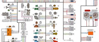
Electrical diagram of the ECM of a VAZ-21101 with controller 21114-1411020-30/31/32
List of elements of the electrical connection diagram of the ECM EURO-2 M7.9.7 vehicle 21101:
1 - controller; 2 — block of the ignition system harness to the ABS cabin group harness; 3 — diagnostic block; 4 — immobilizer warning sensor; 5 — immobilizer control unit; 6 — ignition coil; 7 — spark plugs; 8 — nozzles; 9 — electric fuel pump; 10 — block of the ignition system harness to the fuel level sensor harness; 11 — block of the fuel level sensor harness to the ignition system harness; 12 — block of the ignition system harness to the injector harness; 13 — injector harness block to the ignition system harness; 14 — speed sensor; 15 — idle speed regulator; 16 — throttle position sensor; 17 — coolant temperature sensor; 18 — mass air flow sensor; 19 — oil pressure warning lamp sensor; 20 - phase sensor; 21 — oxygen sensor; 22 — crankshaft position sensor; 23 — knock sensor; 24 — solenoid valve for purge of the adsorber; 26 — coolant temperature indicator sensor; 27 — block of the ignition system harness to the instrument panel harness; 28 — block of the instrument panel harness to the ignition system harness; 29 — controller power supply fuse; 30 - ignition relay; 31 - ignition relay fuse; 32 — fuse for the electric fuel pump power supply circuit; 33 — electric fuel pump relay; 34 — electric fan relay; 35 — ignition system harness block to the air conditioner connector; 36 — block of the ignition system harness to the side door harness. 37 — electric fan of the cooling system; 38 — diagnostic connector; 39 — ignition switch; 40 — instrument cluster; 41 — on-board control system unit; 42 — starter relay; 43 — contacts of the 8-terminal blocks of the instrument panel harness and the front harness; 44 — contacts of the 21-terminal blocks of the instrument panel harness and the rear harness; 45 - trip computer.
A - to the “plus” terminal of the battery; B1 — grounding point of the fuel level sensor harness; B2, B3 — grounding points of the ignition system harness; C - to the starter; D - to the driver's door interior lamp switch.
The wires in this diagram have a letter designation of color and a designation of the number of the circuit element to which this wire is connected. The number of the block contact is indicated through the fraction.
Article: 346027
Order code: 095401
- Buy with this product
- show more
Buy analogues
- There are no reviews for this product yet.
Schematic electrical diagrams, connecting devices and pinouts of connectors
The fuel pump on a car is designed to supply fuel to the combustion chamber. Its operation is controlled using a relay. On a VAZ (depending on the model), the fuel supply unit can be electrical or mechanical - it all depends on the fuel supply system. On a fuel-injected car, the fuel pump is located in the tank. When the ignition is turned on, voltage is supplied to the terminals of the unit and it begins to pump fuel. If the required pressure is created in the system, the relay automatically turns off the fuel pump - the engine is ready to start.
When the ignition is turned on, the relay creates pressure in the fuel lines by turning on the fuel pump (BN) for a couple of seconds. After this, the BN will work either when the engine is cranked by the starter, or when the engine is running.
Sometimes this system needs repairs - there is nothing complicated here, and the editors of the 2Skhema.ru website will tell you how to do it yourself. Let's start with the BN pinout, then we will indicate it on the diagrams and at the end there will be instructions for replacing the fuel supply elements.