Modern engines with an injection intake system are equipped with controllers (electronic control units - ECUs), which, based on commands from sensors, control the operation of the fuel system according to a given algorithm. The same engine can be equipped with controllers of various types. While performing the same function, most controllers are not compatible with each other, both in terms of operating algorithm and interaction with sensors, and in terms of electrical connections. In particular, the pinout of VAZ 2114 ECUs of different types may be the same, but with differences in the operating algorithm.
The most common types of ECUs are:
- January 7.2
- January 4.0
- Bosch M5.4;
- Bosch M9.7;
- Itelma 5.1
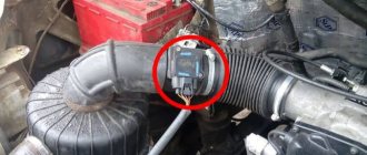
Useful : Where is the mass of the VAZ 2114 ECU (photo and video)
Of the listed January 7.2, electrical wiring is fully compatible with Bosch M7.9.7 and has the same connector. Itelma 5.1 and Bosch M1.5.4 ECUs are also compatible.
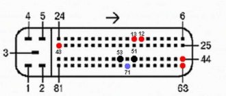
The pinout of the VAZ 2114 8-valve ECU is similar to the 16-valve power unit. The differences lie in the operating algorithm (firmware)
Frequent malfunctions of the VAZ electronic control unit
Considering that the controller is a complex electronic device, failure of the ECU cannot be ruled out.
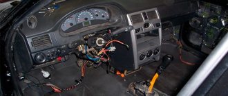
As a rule, the causes of ECU malfunction can be different, ranging from mechanical damage to software failures. For example, a common cause of breakdowns is overheating or liquid ingress. As practice shows, on the Lada Samara the ECU is located near the heater radiator. It is not difficult to guess that a radiator leak and coolant entering the controller often disables this device.
In this case, the check engine light does not always light up on the panel, but the engine malfunctions. In such a situation, when no other causes have been identified, what is needed is not diagnostics of the engine and systems, but professional diagnostics of the car's ECU, which can only be performed by an experienced specialist. Often, after checking, the unit may need to be replaced, since ECU repair is often not recommended.
Repair and diagnostics of control units
The VAZ 2114 controller often breaks down. The system has a self-diagnosis function - the ECU queries all components and issues a conclusion about their suitability for operation. If any element fails, the “Check Engine” lamp will light up on the dashboard. It is possible to find out which sensor or actuator has failed only with the help of special diagnostic equipment. Even with the help of the famous OBD-Scan ELM-327, loved by many for its ease of use, you can read all engine operating parameters, find the error, eliminate it and delete it from the memory of the VAZ 2114 ECU.
Of course, it is wrong to simply delete errors. Be careful, because malfunctions don’t just appear. A good example is that a friend’s oxygen sensor broke down. And every other day he cuts down the mistake so that “it doesn’t become an eyesore.” But the reason lies in a faulty lambda. But what to do if the ECU does not want to respond to the scanner at all? Then check the following:
- Is there any mechanical damage to the housing, including oxidation and corrosion?
- The fuse is working properly, there is voltage and a connection to the power supply minus.
- Is the device overheating?
It is unlikely that you will be able to repair the control unit yourself; the work is too delicate. You can only replace it with a new one with your own hands.
Why the scanner does not connect to the VAZ 2110 ECU and how to fix it
Often, car owners are faced with the problem of the inability to connect a device with a control module, why does this happen:
- You purchased a low-quality adapter. In this case, we are not talking about the firmware, but rather about the inoperability of the hardware, which is typical for defective devices. If the board fails or is initially inoperative, then it will be impossible to check the operation of the motor. Accordingly, how to connect to the control unit.
- Damaged or defective cable that prevents device communication. It is necessary to diagnose the wire to identify damage.
- Another reason why there may be no connection is due to bad firmware. If the software version is too old, it will be impossible to synchronize the device with the car.
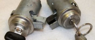
Siemens Deka injectors
There is no certainty with Siemens injectors, since the plant can install injectors of different markings on the same engine. However, there is a clear difference between the injectors for eight-valve and 16-valve engines.
They are marked as VAZ20734 (orange markings) and 20735 (blue markings). On eight-valve engines, a Siemens 6393 nozzle with a thick torch can be used. Its productivity is 1.662 mg/sec, and its operating pressure is 3 atm. Each of these injectors can be installed on a VAZ-2114 engine.
Injector Siemens-vaz20734 Injector Siemens-vaz20735
Article: 346027
Order code: 095401
- Buy with this product
- show more
Buy analogues
- There are no reviews for this product yet.
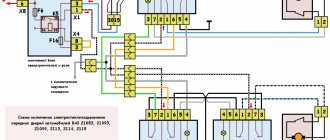
Schematic electrical diagrams, connecting devices and pinouts of connectors
The fuel pump on a car is designed to supply fuel to the combustion chamber. Its operation is controlled using a relay. On a VAZ (depending on the model), the fuel supply unit can be electrical or mechanical - it all depends on the fuel supply system. On a fuel-injected car, the fuel pump is located in the tank. When the ignition is turned on, voltage is supplied to the terminals of the unit and it begins to pump fuel. If the required pressure is created in the system, the relay automatically turns off the fuel pump - the engine is ready to start.
When the ignition is turned on, the relay creates pressure in the fuel lines by turning on the fuel pump (BN) for a couple of seconds. After this, the BN will work either when the engine is cranked by the starter, or when the engine is running.
Sometimes this system needs repairs - there is nothing complicated here, and the editors of the 2Skhema.ru website will tell you how to do it yourself. Let's start with the BN pinout, then we will indicate it on the diagrams and at the end there will be instructions for replacing the fuel supply elements.
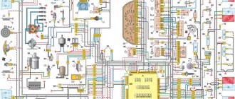
VAZ 2114 wiring diagram
Advice: if you want to understand the operation of a car’s ignition and power system, it would be a good idea to watch video materials from a school physics course. Sound signal and relay for its activation.
Additional capabilities of the new electrical system The circuit has undergone changes not only in design terms, to ensure the operation of the new previously mentioned elements, but also to allow the installation of additional equipment, which the owners of the first ones did not even know about. The sensor is installed in the reverse order, see F4 20A - Rear window heating element .
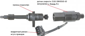
Repair will not be practical if the needle guide drive is worn out. Years of production: Relay for turning on electric lifts.
A wiring harness has been added for connecting to the electronic switch. Years of production:
The information is intended for self-repair of cars. Gearmotor and windshield wiper activation relay. Repairs on a forced 1.6-liter engine are a little more complicated: First you need to remove the protective casing and loosen the clamp securing the air filter pipe. Valve for turning on headlight washers.
Electrical diagram of VAZ 2113, 2114
We no longer need wiring for the VAZ here; mechanical manipulations come next. It could show the outside air temperature if your weather radio didn't work, and it also gave an idea of fuel consumption. To accurately check your oxygen sensor, see
F15 7. Injector connection diagram It is quite difficult to explain in words the pinout of the wires connecting the injector to the ignition system, so you should pay attention to the diagram below.
You can heat the sensor and unscrew it while heated. Engine compartment lamp. VAZ 2110 starter circuit; eleven; 12. In detail and in detail.
How to remove the mounting block - all steps in one video
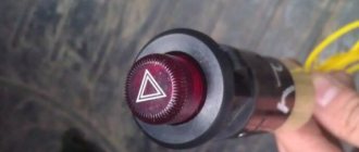
Left: If the turn signals work properly but the hazard warning lights do not turn on, the cause is usually a faulty hazard warning light switch. If you press the switch firmly several times, most often it will start working normally. If this does not happen, then remove the switch (2), squeezing its locking tabs and removing it from the groove, check the contacts of the pin connection (1). Right: When installing the brake light switch (2), it must be pressed against the pedal support (3) so that the switch pin also presses the switch when the pedal (4) is released. For perfect operation, the pin block (1) must be correctly connected.
VAZ-2112 harness diagrams
Instrument panel harness diagram
1, 2, 3, 4 – instrument panel harness pads to the front harness; 5 — block of the instrument panel harness to the side door harness; 6, 7, 8 — instrument panel harness pads to the rear harness; 9 – rear window heating switch; 10 – light signaling switch; 11 – windshield wiper switch; 12 – block of the instrument panel harness to the radio; 13 – mounting block; 14 — instrument cluster; 15 – heater control controller; 16 – heater motor switch; 17 — block of the instrument panel harness to the ignition system harness; 18, 19 — blocks of the instrument panel harness to the air supply box harness; 20 — ignition switch; 21 – fog lamp relay; 22 – sound signal relay; 23 — power window relay; 24 — starter relay; 25 – seat heating relay; 26 – external lighting switch; 27 – fog lamp switch; 28 – cigarette lighter; 29 – lampshade lighting of the glove box; 30 – glove box lighting switch; 31 – switch for rear fog lights; 32 – right steering column switch; 33 – socket for connecting a portable lamp; 34 — instrument lighting switch; 35 – brake signal switch; 36 – sound signal switch; 37 – alarm switch; 38 – air distribution drive gearmotor; 39 – VAZ-2112 illuminator; 40 — instrument panel harness block to the front harness; 41 – trunk lock drive switch; 42 – rear fog light relay.
A – grounding point of the instrument panel harness.
Source
Commercial firmware JANUARY 7.2 for HBO
| Single-mode versions | |
| 201CB5711183 – 1411020-22 | Single-mode version optimized for basic LPG movement. Without DC, with CO adjustment from diagnostic equipment. Cost 1000 ₽. |
| 203RB402111 – 1411020-81(82) | Single-mode version optimized for basic LPG movement. Without DC, with CO adjustment from diagnostic equipment. Calibration by Aviacop Tuning Lab. Cost 1000 ₽. |
| 204RB4021114 – 1411020-31(32) | Single-mode version optimized for basic LPG movement. Without DC, CO adjustment with diagnostic. equipment. Protocol Russia-83. Cost 1000 ₽. |
| 205RB4021124 – 1411020-31(32) | Single-mode version based on the I205DX53_RCO software, optimized for the main movement on the HBO. Without DC, with CO adjustment from diagnostic equipment. Protocol Russia-83. Calibration by Aviacop Tuning Lab. Cost 1000 ₽. |
| 226BX1221067 – 1411020-11(12) | Single-mode version optimized for basic LPG movement. Without DC, with CO adjustment from diagnostic equipment. Calibration by Aviacop Tuning Lab. Cost 1000 ₽. |
| Dual mode versions | |
| 201CDB5711183 – 1411020-22 | Dual-mode Standard/Butane version. When switching to GAS, the injectors and BN are switched off by software. Cost 1200 ₽. |
| 203DRB402111 – 1411020-81(82) Dual-mode version | Dual-mode version Speaker/Butane. The dynamic commercial version I203DX36 is used as the gasoline version, and I203RB40 as the butane version. When switching to GAS, the injectors are switched off programmatically. Cost 1200 ₽. |
| 204DRB4021114 – 1411020-31(32) Dual-mode version | Dual-mode version Speaker/Butane. The dynamic commercial version I204DX55 is used as the gasoline version, and I204RB40 as the butane version. When switching to GAS, the injectors are switched off programmatically. Cost 1200 ₽. |
| 205DRB4021124 – 1411020-31(32) Dual-mode version | Dual-mode version Speaker/Butane. The dynamic commercial version I205DX53 is used as the gasoline version, and I205RB40 as the butane version. When switching to GAS, the injectors are switched off programmatically. Cost 1200 ₽. |
| 226BP1221067 – 1411020-11(12) Dual-mode version | Dual-mode version Dynamic/Butane for “Classic”. The dynamic commercial version I226FX12_RCO is used as the gasoline version, and I226BX12_RCO as the butane version. BN and injectors cannot be turned off by software, an emulator is required. Cost 1200 ₽. |
| 226BFX5321067 – 1411020-11(12) Dual-mode version | Dual-mode version Dynamic/Butane for “Classic”. As a basic version, a dynamic commercial version based on “front-wheel drive” software was used; when switching to GAZ, the injectors are turned off by software, and a correction was made to work with LPG. Cost 1200 ₽. |
| 214BXF2 Dual mode version | Dual-mode version Dynamic/Butane to replace Bosch M7.9.7 controllers for January 7.2 Niva vehicles. As a basic version, a dynamic commercial version is used based on “front-wheel drive” software, with 2 cooling fans; when switching to GAS, the injectors are turned off by software, and a correction has been made to work with LPG. Version for fuel systems with return. Cost 1200 ₽. |
| 220BXF2 Dual mode version | Dual-mode version Dynamic/Butane to replace Bosch M7.9.7 controllers for January 7.2 Niva-Chevrolet vehicles. As a basic version, a dynamic commercial version is used based on “front-wheel drive” software, with 2 cooling fans; when switching to GAS, the injectors are switched off by software, and a correction has been made to work with LPG. For fuel systems without return. Cost 1200 ₽. |
Where is the VAZ ECU located and the interchangeability of control units
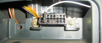
First of all, to determine the type of control unit, you need to find its installation location in the car. To do this, you should study the manual. As an example, let's look at the VAZ 2108 - 2115. On these cars, the ECU is located in the passenger compartment, on the front right, slightly below the glove compartment.
By the way, this information is also useful for computer diagnostics, since you need to know where you can connect to the diagnostic connector installed in various places on a particular model.
As for the units themselves, VAZ 2108 - 2115 of different years of production have different ECU models. For example, the most popular ECU January 4 was installed on early models of injection engines with central injection into the intake manifold.
Version January 5 - 6 are ECUs with distributed injection, but without oxygen sensor support. The January 7 control unit has appeared on cars since 2007, supports all sensors, and effectively controls the engine.
Let us also add that in addition to January, different generations of GM units were actively used at VAZ, being an analogy of January 4 - 7. The same can be said about Bosch or Itelma ECUs. Taking into account all the features, interchangeability is possible, but you need to select analogues that are suitable for the class, version, number of supported sensors, etc.
The fact is that each model is only suitable for a certain combination of engine and sensors, as well as wiring and firmware. This means that different models, even within the same family, can only be installed taking into account full compatibility.
To accurately identify the ECU, just remove the instrument panel frame from the side and write down the ECU number. Also, if you have a BC, you can optionally view the version and type of the ECU, as well as the firmware number of the unit
Electrical diagram of the VAZ-21104 ECM with controller 21124-1411020-30/31/32
1 — block of the ignition coil wiring harness to the ignition system harness; 2 — block of the ignition system harness to the ignition coil wiring harness; 3 — ignition coils; 4 — immobilizer warning sensor; 5 — immobilizer control unit; 6 — spark plugs; 7 — nozzles; 8 — diagnostic block; 9 — block of the ignition system harness to the ABS cabin group harness; 10 - controller; 11 — electric fuel pump; 12 — block of the ignition system harness to the fuel level sensor harness; 13 — block of the fuel level sensor harness to the ignition system harness; 14 — block of the ignition system harness to the injector harness; 15 — injector harness block to the ignition system harness; 16 — block of the ignition system harness to the side door harness; 17 — speed sensor; 18 — idle speed regulator; 19 — throttle position sensor; 20 — coolant temperature sensor; 21 — mass air flow sensor; 22 — oil pressure warning lamp sensor; 23 - phase sensor; 24 — oxygen sensor; 25 — crankshaft position sensor; 26 — knock sensor; 27 — solenoid valve for purge of the adsorber; 28 — oil level sensor; 29 — coolant temperature indicator sensor; 30 — block of the ignition system harness to the instrument panel harness; 31 — block of the instrument panel harness to the ignition system harness; 32 — ignition relay; 33 - ignition relay fuse; 34 — fuse for the electric fuel pump power supply circuit; 35 — electric fuel pump relay; 36 — electric fan relay; 37 — controller power supply fuse; 38 — ignition system harness block to the air conditioner connector; 39 — instrument cluster; 40 — ignition switch; 41 — electric fan of the cooling system; 42 — on-board control system unit; 43 — starter relay; 44 — contacts of the 8-terminal blocks of the instrument panel harness and the front harness; 45 — contacts of the 21-terminal blocks of the instrument panel harness and the rear harness; 46 — trip computer; 47 - diagnostic connector.
Appearance and body structure
As for the dimensions, the VAZ-2112 (16 valves) decreased in length by 93 mm. This change occurred in the rear overhang area. But despite all this, the size of the wheelbase did not transform. The body length was 4170 mm. And the height of 1676 mm and width of 1430 mm remained classic for the “tenth” family. The top line on this body very smoothly transforms into a rather small rear overhang and a huge wing. This design allowed the developers to make the car more manageable.
The one hundred percent zinc-coated body of the “10”, which at one time became very popular, is still susceptible to corrosion. Many owners of new cars did not consider it necessary to perform anti-corrosion treatment. The bottom was rapidly rusting to holes.
Why ELM 327 does not connect to the VAZ 2110 ECU
So, why doesn't ELM327 see the ECU? What should I do so that the device can connect and see the block? Today you can find many different adapters for testing a vehicle on sale. If you buy an ELM327 Bluetooth, most likely you are trying to connect a low-quality device. Or rather, you could have purchased an adapter with an outdated version of the software.
ELM327 Bluetooth devices with outdated firmware use a different Bluetooth module that allows you to interact with two of the available six protocols. Accordingly, you can synchronize the device with a smartphone, but when you try to connect the device to the control unit, it will inform you that there is no connection with the ECU.
So, for what reasons does the device refuse to connect to the block:
- The adapter itself is of poor quality.
- Problems can be with both the device’s firmware and its hardware. If the main microcircuit is inoperative, it will be impossible to diagnose the engine operation, as well as connect to the computer.
- Bad connection cable. The cable may be broken or inoperative itself. The wrong version of the software is installed on the device, as a result of which it will not be possible to achieve synchronization (the author of the video about testing the device is Rus Radarov)
If you own a device with the correct firmware version 1.5, where all six of the six protocols are present, but the adapter does not connect to the ECU, there is a way out. You can connect to the unit using initialization strings, which allow the device to adapt to the commands of the machine’s motor control unit. In particular, we are talking about initialization lines for diagnostic utilities HobDrive and Torque for vehicles that use non-standard connection protocols.
How to deceive the mass air flow sensor using ECU firmware
The good thing about the previous method is that its implementation does not require complex equipment or painstaking work. If you were able to check the voltage at the output of the flow meter with a multimeter (which means you at least have one), and know how to hold a soldering iron in your hands, installing a resistor in the wire gap will not be difficult. However, the dependence of voltage on air flow mass is nonlinear. And when the throttle valve opens, the error of the signal corrected by the resistor at rest will increase. Accordingly, the fuel-air mixture will not be ideal.
This means that you need to adjust the MAF calibration in the ECU firmware.
- We install the specialized tuning program “DFID Corrector” on the laptop.
- We connect the car scanner to the OBD-II connector and establish communication between the ECU and the computer.
- We adjust the voltage of the MAF ADC at rest (air mass 0 kg/hour) to the required 1 V.
- Save the firmware changes.
After calibration, the data on mass air flow will be correct throughout the entire engine speed range.
This is interesting: What gap should be on the Hyundai Solaris on the spark plugs
ECU pinout VAZ 21124 16 valves injector diagram
ECU block number: 21124-1411020-30, 21124-1411020-31.32
1 — ignition coil wiring harness block to the ignition system harness 2 — ignition system harness block to the ignition coil wiring harness 3 — ignition coils 4 — immobilizer warning sensor 5 — immobilizer control unit 6 — spark plugs 7 — injectors 8 — diagnostic block 9 — ignition system harness connector to the ABS cabin group harness 10 — controller 11 — electric fuel pump 12 — ignition system harness connector to the fuel level sensor harness 13 — fuel level sensor harness connector to the ignition system harness 14 — ignition system harness connector to the injector harness 15 — harness connector injectors to the ignition system harness 16 — ignition system harness block to the side door harness 17 — speed sensor 18 — idle speed control 19 — throttle position sensor 20 — coolant temperature sensor 21 — mass air flow sensor 22 — oil pressure warning lamp sensor 23 — camshaft position sensor (phases) 24 — oxygen sensor 25 — crankshaft position sensor 26 — knock sensor 27 — canister purge solenoid valve 28 — coolant temperature indicator sensor 29 — ignition system harness connector to instrument panel harness 30 — panel harness connector devices to the ignition system harness 31 — ignition relay 32 — ignition relay fuse 33 — electric fuel pump power circuit fuse 34 — electric fuel pump relay 35 — electric fan relay 36 — controller power circuit fuse 37 — ignition system harness block to the air conditioner connector 38 — instrument cluster 39 — switch ignition 40 — electric fan of the cooling system 41 — on-board control system unit 42 — additional starter relay 43 — contacts of the 8-terminal blocks of the instrument panel harness and the front harness 44 — contacts of the 21-terminal blocks of the instrument panel harness and the rear harness 45 — trip computer 46 — diagnostic connector
A, E - to the plus terminal of the battery B1 - grounding point of the ignition coil wiring harness B2 - grounding point of the fuel level sensor harness B3, B4 - grounding points of the ignition system harness C - to the starter D - to the driver's door interior lamp switch
Source
Instructions for removing and replacing the computer
The need to dismantle the ECM unit 16 of the ten valve engine arises if repairs are necessary when faults are identified. The repair process itself will depend on what exactly happened in the operation of the ECU. For example, if the contacts on the module connector have oxidized, the unit must be dismantled to clean or replace them. If the reason lies in damage to the housing, then the device must be removed for replacement; if water has gotten inside, then the module should be removed in order to dry it. Only after you have dried the block can it be tested.
Malfunctions of the central unit of body electronics TsBKE
The TsBKE 21900-3840080-10/20 block is designed to perform many functions.
This includes control of external and internal lighting lamps, door locks, windshield wipers, alarm systems, heated seats, electric mirror drives, etc. Installed on Priora, Kalina, Granta cars.
The turns on the Priora do not work, the right turn signals on the Kalina, Priora, and Grant are constantly on. Owners constantly call us on the phone with questions like this. The body electronics unit of modern AvtoVAZ cars does not stand the test of time.
The main signs of a faulty ECU of VAZ cars:
- Turn signals do not work;
- one side of the turn signals is constantly on;
- The trunk opening function does not work;
- no control of one or more functions;
- All functions of the unit do not work, diagnostics are not possible.
“Comfort block”
VAZ cars often fail. Problems with this unit are common, and replacing the unit is not always cheap. A new block costs 6-7 tr. plus 1.5 rub. block replacement. Of course, you can find a used version, but it will take a lot of time.
We offer prompt repairs
“comfort block”.
Wiring diagram VAZ-2114 new models
The updated engine has a new injection scheme, so it was necessary to use some new devices, as well as replace the ignition coil with a more efficient one and adapted to Euro 3 conditions. In order to comply with them, the engine had to minimize the amount of CO at start-up. And for this it was necessary to lean the mixture. Since a lean mixture ignites worse, it needed a more powerful spark to spark. This explains the use of a coil of increased power.
- block headlights;
- gearmotors for headlight cleaners*;
- fog lights*;
- ambient temperature sensor;
- sound signals;
- engine compartment light switch;
- engine cooling fan electric motor;
- generator VAZ-2114;
- low oil level indicator sensor;
- washer fluid level sensor;
- front brake pad wear sensor;
- wire ends connected to the common windshield washer pump**;
- windshield washer pump;
- headlight washer pump*;
- wire ends for connecting to the rear window washer pump on VAZ-2113 and VAZ-2114 cars;
- low oil pressure indicator sensor;
- engine compartment lamp;
- wire lug for connecting to the engine management system wiring harness;
- windshield wiper gear motor;
- starter VAZ-2114;
- block connected to the wiring harness of the ignition system on carburetor cars;
- coolant temperature indicator sensor;
- reverse light switch;
- low brake fluid level indicator sensor;
- accumulator battery;
- low coolant level indicator sensor;
- relay for turning on fog lights;
- mounting block;
- brake light switch;
- plug socket for a portable lamp;
- hydrocorrector scale illumination lamp;
- parking brake indicator lamp switch;
- block for connecting a backlight lamp;
- switch for instrument lighting lamps;
- Understeering's shifter;
- hazard switch;
- front seat heating element relay;
- ignition switch;
- rear fog lamp circuit fuse;
- front seat heating elements circuit fuse;
- door lock circuit fuse;
- front ashtray illumination lamp;
- ignition relay;
- cigarette lighter VAZ-2114;
- glove box lighting lamp;
- glove compartment light switch;
- heater fan motor;
- additional heater motor resistor;
- heater fan switch;
- heater switch illumination lamp;
- heater lever illumination lamp;
- gear motors for electric windows of the front doors;
- right front door ESP switch (located in the right door);
- gear motors for locking front door locks;
- wires for connecting to the right front speaker;
- gear motors for locking rear doors;
- wires for connecting to the right rear speaker;
- door lock control unit;
- wires for connecting to radio equipment;
- headlight wiper switch*;
- rear window heating element switch;
- rear fog light relay;
- block for connection to the heating element of the right front seat;
- rear fog light switch;
- right front seat heating element switch;
- fog light switch*;
- switch for external lighting lamps;
- left front seat heating element switch;
- block for connection to the heating element of the left front seat;
- wires for connecting to the left front speaker;
- left front door power window switch (located in the left door);
- right front door power window switch (located in the left door);
- wires for connecting to the left rear speaker;
- side direction indicators;
- dome light switches on the front door pillars;
- dome light switches on the rear door pillars;
- lampshade VAZ 2114;
- individual interior lighting lamp;
- block for connecting to the wiring harness of the electric fuel pump;
- trunk light switch;
- instrument cluster;
- trunk light;
- on-board control system display unit;
- trip computer*;
- block for connecting the wiring harness of the engine management system;
- rear exterior lights;
- rear interior lights;
- pads for connecting to the rear window heating element;
- license plate lights;
- additional brake signal located on the spoiler.
Numbering order of plugs in blocks:
A - headlight units and headlight cleaners; B - cigarette lighter; B - mounting block, instrument cluster, ignition switch, windshield wiper and other electrical components (for blocks with a different number of plugs, the numbering order is similar); G — relay for turning on the rear fog light; D — alarm switch; E — electric window motors and door lock motors; F — interior lamp.
In the instrument panel wiring harness, the second ends of the white wires are brought together into one point, which is connected to the instrument lighting switch (except for the white wire, from plug “4” of block “X2” of mounting block 28 to display block 83 of the on-board control system). The second ends of the black wires are also brought together to points connected to ground. The second ends of the yellow wires with a blue stripe are brought together to a point connected to plug “4” of the “X1” block of the mounting block. The second ends of the white wires with a red stripe are brought together to a point connected to plug “10” of the “X4” block of the mounting block. The second ends of the orange wires are brought together to a point connected to plug “3” of the “X4” block of the mounting block.
Explanations for the 8-pin injector block: white-red and blue - for the check light bulb, blue-red - ignition, gray - speed sensor, brown-red - tachometer, blue-white - driver's door switch (for the immobilizer), green- red - K-line (may not exist), green - fuel consumption. Next to it is a pink wire - to the fuel level sensor.
Serial firmware VAZ Bosch M7.9.7+
Bosch M7.9.7 new hardware implementation (M7.9.7+) Software ID VAZ number Note B103EQ12 2111 – 1411020-80 1 Serial version for new hardware implementation, E2 standards B103ER12 2111 – 1411020-80 2 Serial version for new hardware implementation, E2 standards B104DQ17 21114 – 1411020-30 1 Serial version for new hardware implementation, E2 standards B104DR17 21114 – 1411020-30 2 Serial version for new hardware implementation, E2 standards B105DQ09 21124 – 1411020-30 1 Serial version for new hardware implementation, E2 B1 standards 05DR09 21124 – 1411020-30 2 Serial version for new hardware implementation, standard E2 B105DR10 21124 – 1411020-30 3 Serial version for new hardware implementation
ECU made in France, E2 standards B108DQ09 21124 – 1411020-10 1 Serial version for new hardware implementation, E3 standards B108DR09 21124 – 1411020-10 2 Serial version for new hardware implementation, E3 standards B109DR02 21124 – 1411020-20 3 Serial version for new device noah implementations, E3 standards B119DQ01 21114 – 1411020-20 1 Euro‑3 serial version for new hardware implementation, XC05_M7A1, E3 standards B119DR02 21114 – 1411020-20 Bogdan, serial version, software XC06_M7A1, E4 standards B120EQ16 21214 – 1411020-30 1 Serial version for new hardware implementation, E2 standards B120ER16 21214 – 1411020-30 2 Serial version for new hardware implementation, E2 standards B120ER19 21214 – 1411020-30 3 Serial version for new hardware implementation, E2 standards B122HR01 21230 – 1411020-90 1 Serial version for new hardware implementation on Niva - Chevrolet vehicles, E2 standards Attention! The firmware has a problem with turning on the fans B122HR91 21230 – 1411020-90 2 Serial version for the new hardware implementation on Niva – Chevrolet, E2 standards 22XC052S 21230 – 1411020 “Clone” B122HR01, E4 standards 22YC041S 21230 – 1411020- 40 Niva – Chevrolet, E4 standards B114ER18 21214 – 1411020-20 Serial version for the new hardware implementation on the Niva 21214 car, E3 standards B114ER17 21214 – 1411020-20 Serial version for the new hardware implementation on the Niva 21214 car. Version from the export car, E3 standards B126ES01 2104 – 1411020-10 1 Serial version for the new hardware implementation for 1.45 l classic cars, E2 standards B126ER02 2104 – 1411020-10 2 Serial version for the new hardware implementation for 1.45 l classic cars, norms E2 B102CQ05 Kalina 1 Serial for Kalina, standards E3 B102CR06 Kalina 2 Serial for Kalina, standards E3 B101CR01 11183 – 1411020-02 1 Serial for Kalina, standards E2 B101CR02 11183 – 1411020-02 2 Serial for Kalina, standards E2 B104CR 01 21114 – 1411020- 40 Viburnum, paper nameplate, E3 standards B104CR02 21114 – 1411020-40 Viburnum, differences from CR01 only in fan temperature thresholds, E3 standards B103CU03 21114 – 1411020-40 Viburnum, paper nameplate, without DND, E3 standards B173DR01 21126 – 141102 0-10 1 Serial for Priora, standards E3 B174DR03 21126 – 1411020-00 2 Serial for Priora, standards E4* B174DR04 21126 – 1411020-00 3 Serial for Priora, equipped with power steering, standards E4* B174DT05 21126 – 1411020-30 4 Serial for Pria yell, norms E4* B174DT06 21126 – 1411020-30 5 Serial for Priora, standards E4* B174DT07 21126 – 1411020-00 6 Serial for Priora, standards E4* B173СR03 11194 – 1411020 1 Serial for Kalina 1.4 l., standards E3 B174 CR03 11194 – 1411020 -10 2 Serial version for Kalina 1.4 l., E3 standards B174СT04 11194 – 1411020-10 3 Serial version for Kalina 1.4 l., E3 standards 22YB072S 2123 – 1411020-30 1 Serial version Euro‑3 for new hardware implementation on a /m Niva - Chevrolet, E3 standards OPP firmware** Bosch M7.9.7+ B120ER1733XCO305B133ER17 21214 – 1411020-30 OPP firmware from Niva 1.8 (in identifiers 1.7)
Without phase sensor. 33XCO305 and B133ER17 are “clones” of B120ER17, E2 standards B121ER17 21214 – 1411020-10 Firmware for STC VAZ OPP for the long Niva, E3 standards B11KSS01 11196 – 1411020 STC VAZ OPP firmware for Kalina Sport 1, 6 16V, standard E3 B13KSS02 21126 – 1411020-60 Firmware for OPP STC VAZ for Kalina Sport 1.6 16V. There are two options in the archive with different KS and identifiers, E3 standards
* Toxicity standards are indicated in accordance with IP VAZ ** OPP - Experimental Industrial Enterprise, a subsidiary of AvtoVAZ. Attention! Some firmware for Bosch M7.9.7 can be presented in two forms, in the compressed “Combiloader” format and regular bin files (with the prefix “c”)
Let's compare architectures
At the moment, there are many different ADC architectures in the world. Each of them has its own advantages and disadvantages. There is no architecture that would achieve the maximum values of all the parameters described above. Let's analyze what maximum speed and resolution parameters the companies producing ADCs were able to achieve. We will also evaluate the advantages and disadvantages of each architecture (you can read more about the various architectures in the article on Habr). Architecture comparison table
| Architecture type | Advantages | Flaws | Maximum resolution | Maximum sampling rate |
| flash | Fast converter. The conversion is carried out in one clock cycle. | High power consumption. Limited resolution. Requires a large crystal area (comparators). It is difficult to coordinate a large number of elements (as a result, low yield). | 14 bit 128 kSa/s AD679 | 3 bit 26 GS/s HMCAD5831 |
| folding-interpolated | Fast converter. The conversion is carried out in one clock cycle. Requires fewer comparators due to preliminary “convolution” of the entire processing range into a narrower range. Occupies less space. | Errors associated with the nonlinearity of the convolution block. Delay for establishing levels in the convolution block, which reduces the maximum fs. Medium resolution. | 12 bit 6.4 GS/s ADC12DL3200 | 12 bit 6.4 GS/s ADC12DL3200 |
| SAR | High accuracy. Low power consumption. Easy to use. | Limited speed. | 32 bit 1 MSa/s LTC2500 | 10 bit 40 MSa/s XRD64L43 |
| pipeline | Fast converter. Highest accuracy among fast ADCs. Doesn't take up a large area. Has lower consumption among similar fast converters. | Pipeline delay. | 24 bit 192 kSa/s AK5386 | 12 bit 10.25 GS/s AD9213 |
| dual-slope | Average conversion accuracy. Simplicity of design. Low consumption. Resistance to changes in environmental factors. | Processes low frequency Signals (low fs). Mediocre resolution. | 12+sign bit 10 S/s TC7109 | 5+sign bits 200 kSa/s HI3-7159 |
| ∑-Δ | The highest conversion accuracy thanks to the “Noise shaping” effect (specific filtering of quantization noise) and oversampling. | Cannot work with wideband signal. | 32 bits 769 kSa/s AK5554 | 12 bit 200MS/s ADRV9009 |
Types of ECU (esud, controller). What kind of ECUs are installed on VAZ?
"January-4", "GM-09"
The very first controllers on SAMARA were January-4, GM - 09. They were installed on the first models before the year 2000. These models were produced both with and without a resonant knock sensor.
The table contains two columns: 1st column – ECU number, second column – brand of “brains”, firmware version, toxicity standard, distinctive features.
| 2111-1411020-22 | January-4, without DC, RSO (resistor), 1st ser. version |
| 2111-1411020-22 | January-4, without recreation center, RSO, 2nd ser. version |
| 2111-1411020-22 | January-4, without recreation center, RSO, 3rd ser. version |
| 2111-1411020-22 | January-4, without recreation center, RSO, 4th ser. version |
| 2111-1411020-20 | GM,GM EFI-4,2111,with DC,USA-83 |
| 2111-1411020-21 | GM, GM EFI-4, 2111, with DC, EURO-2 |
| 2111-1411020-10 | GM,GM EFI-4 2111,with DC |
| 2111-1411020-20 h | GM, RSO |
VAZ 2113-2115 from 2003 are equipped with the following types of ECUs:
"January 5.1.x"
The following types of hardware implementation are distinguished:
- simultaneous injection;
- in pairs - parallel injection;
- phased injection.
Interchangeable with “VS (Itelma) 5.1”, “Bosch M1.5.4”
| 2111-1411020-71 | January-5.1.1, without dk, with |
| 2111-1411020-71 | January-5.1.1, without dk, with |
| 2111-1411020-71 | January-5.1.1, without dk, with |
| 2111-1411020-71 | January-5.1.1, without dk, with |
| 2111-1411020-71 | January-5.1.1, without dk, with |
| 2111-1411020-72 | Itelma, without dk, with |
| 2111-1411020-72 | Itelma, without dk, with |
| 2111-1411020-72 | Itelma, without dk, with |
| 2111-1411020-72 | Itelma, without dk, with |
Car fuses - number, current and description
F1 5 Lighting lamps: numbers, instruments, dimensions on the dashboard, left dimensions, trunk lighting F2 7.5 Low beam in the left headlight F3 10 High beam in the left headlight F4 10 Right front fog lamp F5 30 Door windows F6 15 Portable lamp, cigarette lighter F7 20 Radiator fan, horn F8 20 Heated rear window F9 20 Windshield washer and cleaner F10 20 Reserve F11 5 Clearance on the right side F12 7.5 Low beam in the right headlight F13 10 High beam in the right headlight F14 10 Fog lamp, left F15 20 Heated seats 21124 F16 10 Hazard signal, turn signals F17 7.5 Brake light, ignition switch illumination, interior lighting F18 25 Cigarette lighter, glove compartment light, interior heater F19 10 Reversing lamp, brake light monitoring F20 7.5 Rear fog lights headlights
Source
Frequent malfunctions of the VAZ electronic control unit
Considering that the controller is a complex electronic device, failure of the ECU cannot be ruled out. As a rule, the causes of ECU malfunction can be different, ranging from mechanical damage to software failures.
For example, a common cause of breakdowns is overheating or liquid ingress. As practice shows, on the Lada Samara the ECU is located near the heater radiator. It is not difficult to guess that a radiator leak and coolant entering the controller often disables this device.
In this case, the check engine light does not always light up on the panel, but the engine malfunctions. In such a situation, when no other causes have been identified, what is needed is not diagnostics of the engine and systems, but professional diagnostics of the car's ECU, which can only be performed by an experienced specialist. Often, after checking, the unit may need to be replaced, since ECU repair is often not recommended.
ECU (brains) VAZ
The electronic engine control system detects failures associated with wire breaks, short circuits to each other or to ground. With poor contact quality in the connectors. And also with a malfunction of the sensors themselves. However, there are malfunctions in the power and ignition systems that have external signs that are noticed by the driver, but no fault codes are recorded in the memory of the electronic unit. Main symptoms of malfunctions:.
The electronic engine control system detects failures associated with wire breaks, short circuits to each other or to ground.
How does the ECU work?
At the heart is a microprocessor, which is responsible for the normal functioning of all key devices. On a VAZ 2114 car, the ECU collects data from sensors:
- Vehicle speed.
- Detonations.
- Lambda probe.
- DPKV.
- Air flow.
- TPDZ.
- Phases of injection of the air-fuel mixture.
- Coolant temperatures.
These are reading devices that collect information about the operation of an internal combustion engine. Why does he collect it? It is correct to divide and conquer by the following actuators:
- Fuel supply system (pump, injectors).
- Ignition system.
- Adsorber.
- Ventilation.
- Idle air control (yes, yes, this is not a sensor, but an actuator, no need to be confused).
- Automatic diagnostics.
The block diagram of the electronic control unit on the VAZ 2114 consists of three cascades, each of which has its own memory modules:
- A RAM unit (random access memory) is a system that has short-term memory. It stores all information about errors that occurred during operation during the current engine start. When the ignition is turned off (and the computer is de-energized), all memory is cleared and filled again the next time it starts.
- PROM is a programmable read-only memory device. This is the block in which the fuel map (firmware) of the electronic control unit is stored. It also permanently stores information about all system calibration results. And most importantly, this memory contains the algorithm of the internal combustion engine control system. This memory is permanent and is not erased even if the on-board network is completely disconnected. It is this block that is programmed when the “firmware” procedure is performed to improve the characteristics of the VAZ 2114 car.
- And the last block is the ERPZU. The memory unit is necessary to ensure the normal operation of the anti-theft system on the car. It stores passwords and encodings. Starting the engine is possible only if the data exchanged between the immobilizer and the EEPROM matches.
Let's sum it up
As you can see, by analogy with various foreign cars, VAZ injection engines of different generations are also equipped with controllers of various types. Early versions have simple solutions that are responsible for simple mixture formation and work with a small number of sensors.
At the same time, more modern control units are distinguished by support for distributed injection, more flexible control of the ignition system, as well as the ability to interact with oxygen sensors, etc.
Only after all the nuances have been taken into account can you expect that the engine under ECU control will operate correctly and without failures, and the owner himself will receive stable operation of the power unit and systems, environmental friendliness and maximum efficiency from the engine in different operating modes of the car’s engine.
Modifications of the VAZ-2112 car
VAZ-21120 . Modification with a 16-valve injection engine with a volume of 1.5 liters and a power of 93 horsepower. 14-inch wheels were installed on the car. This modification has a problem with valves bending when the timing belt breaks. The problem can be solved by increasing the depth of the grooves in the piston bottoms.
VAZ-21121 . The car was equipped with a VAZ-21114 8-valve injection engine with a volume of 1.6 liters and a power of 81 horsepower.
VAZ-21122 . Budget modification with an 8-valve injection engine VAZ-2111. The car was produced without electric windows, the wheels were 13 inches in size, and the brakes were unventilated from a VAZ-2108 car.
VAZ-21123 Coupe . Three-door, five-seater hatchback. The only two doors for entering the car are 200 millimeters wider than those of the five-door hatchback, and they are mounted on new, durable hinges. The rear arches of the car have become wider. The engine was installed with a 16-valve injection engine with a volume of 1.6 liters and a power of 90 horsepower. The car was produced from 2002 to 2006 in small quantities, the reason for this was the high cost of the car.
VAZ-21124 . Modification with a 16-valve injection engine VAZ-21124 with a volume of 1.6 liters. Produced from 2004 to 2008. For this type of engine, the problem with valve bending was solved. To do this, the depth of the grooves in the piston heads was increased (up to 6.5 mm). In addition, the design of the cylinder block was changed to achieve a working volume of 1.6 liters, for which its height was increased by 2.3 mm, and the radius of the crankshaft was increased by 2.3 mm accordingly. There were also a number of other minor changes.