Published:
10.03.2017
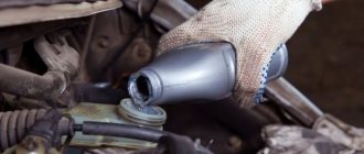
During long-term operation, the parking brake cable of a VAZ-2112 car inevitably stretches, and the brake pads are subject to gradual wear. As a result, the handbrake does not cope effectively with the task assigned to it or stops functioning altogether. If, after stopping the car, you pull the lever, but the brake pads do not hold the wheels in a stationary position, then it is time for repairs. And we are not necessarily talking about replacement, since it is quite likely that the problem can be solved by simply tightening the cable. To do this, you don’t even need to contact a service station - you just need to know how to tighten or replace the handbrake on a VAZ-2112, and do everything yourself.
During operation, the handbrake cable of a VAZ-2112 car inevitably stretches
How does a car's handbrake work? This is perhaps one of the simplest systems, and it consists of such elements as:
- parking brake lever;
- lever lock button;
- handbrake cable with equalizer;
- manual brake system traction;
- adjusting nut and locknut.
There is also a protective cover in the design, and the cable itself passes under the bottom of the machine and is placed in a protective sheath. These are, in fact, all the main parts that make up the parking brake system, if you do not take into account its final element - the brake pads.
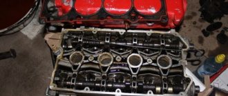
Handbrake VAZ disassembled
Replacing the handbrake cable on a VAZ-2110, 2111, 2112
The handbrake, or scientifically the hand or parking brake, is an irreplaceable part of the car, the benefits of which many people underestimate.
The handbrake is a lever that, in an unexpected situation, will help to perform emergency braking of the car, and in a difficult situation, to move away on a hill, without damaging the cars behind. Yet the main task of the handbrake is to keep the car from accidentally moving. The handbrake makes life much easier for motorists, and sometimes even helps out. Therefore, so that a force majeure situation does not occur and the handbrake does not fail at the necessary moment, you need to monitor the condition of the cable and its serviceability.
How to identify problems with the handbrake? We list the main problems and reasons for the handbrake malfunction.
Basic malfunctions of the hand brake:
- It is difficult or completely impossible to put the car on the handbrake; the cable is difficult to move.
Reason: the threads burst in the middle and fluffed up;
- The car rolls, even with the handbrake raised.
Reason: the cable is loose;
- When I try to put the handbrake on, the car squats to one side.
Reason: one cable broke;
- The handbrake lifts too easily and the car rolls.
Reason: the cable was worn out, the threads began to break.
If a malfunction is detected, the cable should be replaced. If there is no car service nearby, arm yourself with two “13” wrenches, one “10” wrench, a wheelbrace and pliers. Go!
Is adjustment necessary?
First you need to determine whether the adjustment will really solve the problem of the handbrake malfunction.
Adjusting the parking brake
To do this, a small test is carried out. Moreover, it is recommended to do a similar procedure after every 30 thousand kilometers, even if you are sure that the parking brake works well.
Drive your vehicle to an area where there is a slight slope. Place the car on it, turn on the handbrake and shift to neutral. If the car starts to roll down, everything is obvious - the handbrake needs repair.
Replacing the handbrake cable
1. Make sure that the car is not on the handbrake. If so, lower it. To ensure your safety and prevent the car from rolling away, put it at speed and place anti-roll bars under the front wheels.
2. Next, we tear off the wheel bolts with a wheel wrench counterclockwise, “jack up” the car and remove any of the rear wheels.
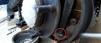
3. We unscrew the two drum bolts and, by screwing them into special holes in the drum, remove it.
4. Using pliers, remove the upper and lower springs, thereby loosening the pads, gaining access to the internal springs, by moving them aside, we can easily remove the pads.
5. Pull the cable out of the brake shield.
6. Loosen the cable holder on the beam and pull the cable out of it.
7. Move the resonator (muffler) to the side by hand; if that doesn’t work, remove the muffler.
8. Loosen the handbrake tensioner nuts (1.8). Remove from the mount (4) and lever (3).
9. Pull the cable jacket out of the equalizer and pull the cable out of the rod.
We do the same with the other wheel.
We assemble in reverse order.
Vacuum booster
1 – vacuum booster housing;
2 – amplifier housing cup; 3 – rod; 4 – adjusting bolt; 5 – rod seal; 6 – sealing ring of the master cylinder flange; 7 – diaphragm return spring; 8 – amplifier pin; 9 – tip mounting flange; 10 – valve; 11 – hose tip; 12 – diaphragm; 13 – amplifier housing cover; 14 – sealing cover; 15 – piston; 16 – protective cover of the valve body; 17 – air filter; 18 – pusher; 19 – pusher return spring; 20 – valve spring; 21 – valve; 22 – valve body bushing; 23 – rod buffer; 24 – valve body; A – vacuum chamber; B – atmospheric chamber; C, D – channels The rubber diaphragm 12 together with the valve body 24 divides the cavity of the vacuum amplifier into two chambers: vacuum A and atmospheric B. Chamber A is connected to the engine inlet pipe through the check valve of the tip 11 and a hose.
The 24 valve body is plastic. At the exit from the cover, it is sealed with a corrugated protective cover 16. The valve body contains the main cylinder drive rod 3 with a support sleeve, rod buffer 23, valve body piston 15, valve assembly 21, pusher and valve return springs 19 and 20, air filter 17 , pusher 18.
When you press the pedal, the pusher 18, the piston 15, and after them the valve 21 move until it stops against the seat of the valve body. In this case, cameras A and B are separated. As the piston moves further, its seat moves away from the valve and through the resulting gap, chamber B is connected to the atmosphere. The air entering through filter 17, the gap between the piston and the valve and channel D creates pressure on the diaphragm 12. Due to the difference in pressure in chambers A and B, the valve body moves along with the rod 3, which acts on the piston of the main cylinder.
Replacement results
After assembly, you should check that the cable has been replaced correctly.
To do this you need:
- Raise the rear of the car using a jack, or drive it into a viewing hole;
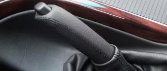
- Lower the lever all the way down;
- Loosen the lock nut and tighten the adjusting nut until the cable is tensioned;
- Check the clicks, the norm is from 2 to 5;
- For reliability, tighten the lock nut, holding the adjusting nut from turning.
We check the operation of the handbrake: put the car on the handbrake and rotate the wheels. The rotation should be uniform and without friction.
To be more confident, choose a steep hill (with an approximate slope of at least 25%) and put the car on the handbrake. Costs? This means the replacement was done correctly.
Wheel cylinder
1 – block stop;
2 – protective cap; 3 – cylinder body; 4 – piston; 5 – seal; 6 – support plate; 7 – spring; 8 – crackers; 9 – thrust ring; 10 – thrust screw; 11 – fitting; A – slot on the thrust ring The brake mechanism of the rear wheel (Fig. Brake mechanism of the rear wheel) is drum, with automatic adjustment of the gap between the shoes and the drum. The automatic clearance adjustment device is located in the wheel cylinder. Its main element is a split thrust ring 9 (Fig. Wheel cylinder), installed on the piston 4 between the shoulder of the thrust screw 10 and two nuts 8 with a gap of 1.25–1.65 mm.
The thrust rings 9 are inserted into the cylinder with tension, providing a shear force of the ring along the cylinder mirror of at least 343 N (35 kgf), which exceeds the force on the piston from tension springs 3 and 7 (see Fig. Brake mechanism of the rear wheel) of the brake pads.
When, due to wear of the linings, the gap of 1.25–1.65 mm is completely removed, the shoulder on the thrust screw 10 (see Fig. Wheel cylinder) is pressed against the shoulder of the ring 9, as a result of which the thrust ring moves after the piston by the amount of wear. When the braking stops, the pistons are moved by the force of the tension springs until the cracks stop against the shoulder of the thrust ring. This automatically maintains the optimal clearance between the pads and the drum.
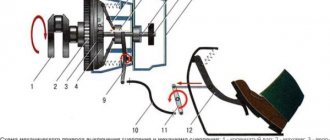
Handbrake diagram for VAZ-2112
For clarity, here is a diagram of a hand brake
1 - button that fixes the handbrake lever; 2 — hand brake lever; 3 — protective cover; 4 — handbrake rod; 5 — cable equalizer; 6 — adjusting nut; 7 - lock nut; 8 - cable; 9 — protective sheath of the cable.
In this circuit we need element number 6 . It is he, and only him!
What is required for adjustment?
In order to adjust the handbrake you need a platform or lift. If there are no such devices, then you can simply hang the rear wheels on the “goats”. They can be installed under the car using a jack. It’s also worth taking two “13” keys and pliers.
- The car is installed on an overpass or “goats”.
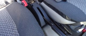
The lever position is set to the lowest possible position.
We put the handbrake at the very bottom. Do not pay attention to the scuffs of the console; we conducted an experiment with non-standard armrests. The iron fastenings of the armrest are visible. The photo shows the editorial car
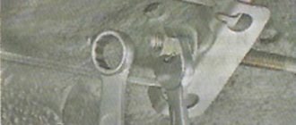
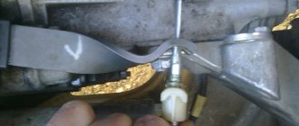
Use a wrench to loosen the locknut.
- The second wrench holds the adjusting nut.
- The adjusting nut should be tightened until the cable is tensioned. It must be remembered that the rod should be held with pliers when tensioning the cable.
Tighten the adjusting nut
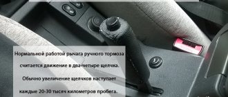
- After this, you should make sure that the full stroke of the handbrake lever is no more than 4 and no less than 2 clicks.
- When the stroke check is completed, the locknut is tightened. The adjustment is held with another key.
- If necessary, change the mechanism to a new one.
Everything is rusty, we changed the adjustment mechanism
- After releasing the adjusted lever down, you should spin the rear wheels. When the lever is in its lowest position, the wheels should spin freely.
If you cannot tighten the cable, then it should be replaced with a new one.
Adjusting the handbrake after tensioning
After adjusting the brakes, you need to check them again. To do this, the car should be placed on a road with a slope of at least 23%! The car should be in neutral gear in this area and with the handbrake pulled up. If the handbrake brakes hold the car in this area, then the handbrake is adjusted correctly.
Master cylinder with reservoir
1 – main cylinder body;
2 – low pressure sealing ring; 3 – drive piston of the “left front–right rear brake” circuit; 4 – spacer ring; 5 – high pressure sealing ring; 6 – pressure spring of the sealing ring; 7 – spring plate; 8 – piston return spring; 9 – washer; 10 – locking screw; 11 – drive piston of the “right front–left rear brake” circuit; 12 – connecting sleeve; 13 – tank; 14 – brake fluid emergency level sensor; A – clearance Master cylinder with sequential arrangement of pistons. A tank 13 is mounted on the master cylinder body, in the filler neck of which a sensor 14 for emergency brake fluid level is installed. The high pressure O-rings 5 and the rear wheel cylinder rings are interchangeable.
How to tighten the handbrake on a Priora - sequence of actions
Main causes of failure
The main reason why such an important device may break and need to be replaced is mechanical wear of the handbrake. As you know, the basis of the system is a small cable that transmits forces from the lever to the mechanism
It actually turns on this node.
The operating conditions of the cable are quite complex - the constant load from the force that the driver transmits through the handbrake lever to the system, sooner or later, can damage the device.
However, the cable breaks extremely rarely - most often, the cables simply jump off. Or the tips fixed in the drum are ground with very long wheel bolts. Needs renovation. Also, the parking brake may not work due to wear on the rear drum brakes (as well as abrasion of the pads, depending on the design).
As a result, the unit ceases to perform the functions assigned to it - the handbrake simply does not hold. The parking brake needs to be replaced and subsequently adjusted. But not everything is so simple - in some cases, the device can be damaged during emergency braking of the car - as a result, it will require repair or replacement.
Often the metal is not completely ground, but the steel fibers are stretched and moving in the shell is very difficult
But it doesn’t matter what the reason for the parking brake failure is, why it doesn’t hold. The purpose of our article is to figure out how to solve the problem
What to do if there is no result
Sometimes motorists are faced with situations in which tightening the cable does not improve the quality of the handbrake. In this case, it is necessary to deal directly with the brakes. The main culprit is the brake pads. They can:
- wear out;
- “get stiff” and not respond to handbrake commands.
Installing new brake pads will help achieve normal results. Experts recommend dismantling the brake drums and checking the movement of the brake pads. If they don't move, it means they're stiff. If there is still movement, the problem must be looked for in other nodes. The primary culprit may be a stretched handbrake cable. If all else fails, it is best to turn to professionals.
Front wheel brake
1 – brake disc;
2 – pad guide; 3 – caliper; 4 – brake pads; 5 – cylinder; 6 – piston; 7 – pad wear indicator; 8 – sealing ring; 9 – protective cover of the guide pin; 10 – guide pin; 11 – protective casing The front wheel brake mechanism is disc, with automatic adjustment of the gap between the pads and the disc, with a floating caliper and a brake pad wear indicator. The bracket is formed by a caliper 3 and a wheel cylinder 5, which are tightened with bolts. The movable bracket is bolted to pins 10, which are installed in the holes of the guide 2 of the pads. Lubricant is placed in these holes, rubber covers 9 are installed between the pins and the pad guide. Brake pads 4 are pressed against the grooves of the guide by springs, the inner one of which has a lining wear indicator 7.
A piston 6 with a sealing ring 8 is installed in the cavity of the cylinder 5. Due to the elasticity of this ring, the optimal gap between the pads and the disk is maintained.
Removing and installing components and adjusting the hand brake VAZ 2110, VAZ 2111, VAZ 2112, Lada Ten
We install the VAZ 2110 car on an inspection ditch or a lift. Removing the parking brake cable is shown using the example of the right cable. Lower the parking brake lever to its lowest position. We remove the manual brake pad drive lever from the cable end of the VAZ 2110 (see Replacing rear brake pads).
Using a 10mm wrench, unscrew the nut of the bracket securing the cable sheath to the rear suspension beam.
Remove the cable fastening bracket.
We remove the cable sheath from the holder.
Using a screwdriver, bend the three brackets securing the cable sheath to the body of the VAZ 2111.
We remove the cable from the brake shield of the VAZ 2111.
Using a wrench and a high 13mm socket, unscrew the locknut and the rod adjusting nut.
We remove the cable tip from the equalizer slot.
Remove the end of the cable sheath from the bracket.
In a similar way, we remove the left parking brake cable of the VAZ 2112. Its dismantling (unlike the right cable) is hindered by the exhaust system.
Remove the cable and equalizer.
To remove the parking brake drive lever and the adjusting rod, unscrew the two nuts from the rod and remove the equalizer (do not dismantle the cables). Remove the cover and housing of the floor tunnel lining (see Removing the VAZ 2112 instrument panel and heater air ducts).
Using a 10mm socket, unscrew the four bolts securing the lever bracket to the floor.
Using a Phillips screwdriver, unscrew the two self-tapping screws securing the parking brake warning lamp switch bracket...
...and remove the bracket with the switch.
Move the lever forward and remove it.
Unsplint the axis of the adjusting rod.
Having taken out the axle, we disconnect the adjusting rod and the lever of the VAZ 2110.
Pressure regulator
1 – pressure regulator housing;
2 – piston; 3 – protective cap; 4, 8 – retaining rings; 5 – piston sleeve; 6 – piston spring; 7 – body bushing; 9, 22 – support washers; 10 – sealing rings of the pusher; 11 – support plate; 12 – pusher bushing spring; 13 – valve seat sealing ring; 14 – valve seat; 15 – sealing gasket; 16 – plug; 17 – valve spring; 18 – valve; 19 – pusher bushing; 20 – pusher; 21 – piston head seal; 23 – piston rod seal; 24 – plug; A, D – chambers connected to the main cylinder; B, C – chambers connected to the wheel cylinders of the rear brakes; K, M, N – clearances The pressure regulator regulates the pressure in the hydraulic drive of the brake mechanisms of the rear wheels depending on the load on the rear axle of the car. It is included in both circuits of the brake system and through it brake fluid flows to both rear brake mechanisms.
Pressure regulator 1 (Fig. Pressure regulator drive) is attached to bracket 9 with two bolts 2 and 16. At the same time, front bolt 2 simultaneously secures fork bracket 3 of lever 5 of the pressure regulator drive. A double-arm lever 5 is hinged on the pin of this bracket with a pin 4. Its upper arm is connected to an elastic lever 10, the other end of which is pivotally connected to the rear suspension arm bracket through an earring 11.
Bracket 3 together with lever 5 can be moved relative to the pressure regulator due to the oval holes for the fastening bolt. This regulates the force with which lever 5 acts on the regulator piston (see subsection 6.4.2). The regulator has four chambers: A and D (Fig. Pressure regulator) are connected to the main cylinder, B to the left, and C to the right wheel cylinders of the rear brakes.
In the initial position of the brake pedal, piston 2 (see Fig. Pressure regulator) is pressed by lever 5 (see Fig. Pressure regulator drive) through leaf spring 7 to pusher 20 (see Fig. Pressure regulator), which is pressed against the saddle under this force 14 of valve 18. In this case, valve 18 is pressed away from the seat and a gap H is formed, as well as a gap K between the piston head and seal 21. Through these gaps, chambers A and D communicate with chambers B and C.
When you press the brake pedal, fluid flows through gaps K and H and chambers B and C into the wheel cylinders of the brake mechanisms. As the fluid pressure increases, the force on the piston increases, tending to push it out of the housing. When the force from the liquid pressure exceeds the force from the elastic lever, the piston begins to move out of the body, and after it, under the action of springs 12 and 17, the pusher 20 moves together with the sleeve 19 and rings 10. In this case, the gap M increases, and the gaps H and K decrease . When the gap H is completely selected and the valve 18 isolates chamber D from chamber C, the pusher 20, together with the parts located on it, stops moving after the piston. Now the pressure in chamber C will vary depending on the pressure in chamber B. With a further increase in the force on the brake pedal, the pressure in chambers D, B and A increases, piston 2 continues to move out of the body, and sleeve 19 together with o-rings 10 and plate 11 under increasing pressure in chamber B, it shifts towards plug 16. At the same time, the gap M begins to decrease. Due to the decrease in the volume of chamber C, the pressure in it, and therefore in the brake drive, increases and will be practically equal to the pressure in chamber B. When the gap K becomes zero, the pressure in chamber B, and therefore in chamber C, will increase less degree than the pressure in chamber A due to throttling of the liquid between the piston head and seal 21. The relationship between the pressure in chambers B and A is determined by the ratio of the difference in the areas of the head and piston rod to the area of the head.
As the vehicle load increases, the elastic lever 10 (see Fig. Pressure regulator drive) is loaded more and the force from lever 5 on the piston increases, that is, the moment of contact between the piston head and seal 21 (see Fig. Pressure regulator) is achieved at greater pressure in the main brake cylinder. Thus, the effectiveness of the rear brakes increases with increasing load.
If the brake circuit “left front – right rear brake” fails, the o-rings 10, bushing 19, under the fluid pressure in chamber B, will move towards the plug 16 until the plate 11 rests on the seat 14. The pressure in the rear brake will be regulated by part of the regulator, which includes piston 2 with seal 21 and bushing 7. The operation of this part of the regulator, in the event of a failure of the said circuit, is similar to the operation with a working system. The nature of the change in pressure at the outlet of the regulator is the same as with a working system.
Modernization
Many modern owners modernize their cars and install so-called hydraulic handbrake here. As a lyrical digression, we note that in this case it is necessary to replace the rear brakes with disc brakes without fail.
Very serious design changes are required - such as installing a hydraulic system in the parking brake. No cables are used here - the parking brake lever is connected to the master cylinder.
After the driver lifts the lever, the brake fluid in the system presses on the cylinders. Most often, hydraulic systems can be found on sports cars - after all, such a brake holds much better.
The main advantages that the hydro system gives:
- Full confidence that the hydraulic handbrake will work;
- There is no need to tighten the cable.
There are some disadvantages:
Sources
- https://masteravaza.ru/tormoza/ruchnoj-tormoz/vaz-2110-zamena-trosa-ruchnika-597
- https://masteravaza.ru/tormoza/ruchnoj-tormoz/vaz-2110-regulirovka-ruchnika-600
- https://vazweb.ru/desyatka/tormoza/zamena-trosa-ruchnika.html