Solex 21083 is a basic carburetor model for engines with a contactless ignition system. It has two dosing systems, an idle system, a diaphragm-type accelerator pump, and a starting device.
Among owners of the VAZ 2108-2109 family, this carburetor is very popular because of its versatility. Having made basic modifications, it can be adapted to an engine of any modification with a volume not exceeding 1.5 cm3.
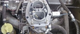
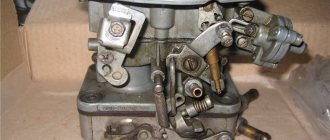
Carburetor
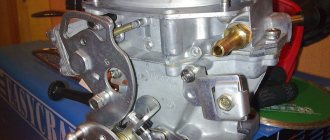
Carburetor appearance
1 – throttle valve zone heating unit; 2 – engine crankcase ventilation fitting; 3 – accelerator pump cover; 4 – electromagnetic shut-off valve; 5 – carburetor cover; 6 – air filter mounting pin; 7 – air damper control lever; 8 – starter cover; 9 – sector of the throttle valve drive lever;
10 – wire block of the EPHH screw sensor; 11 – adjusting screw for the “amount” of idle mixture; 12 – economizer cover; 13 – carburetor body; 14 – fuel supply fitting; 15 – fuel outlet fitting; 16 – adjusting screw for idle mixture composition (arrow); 17 – fitting for supplying vacuum to the vacuum ignition regulator.
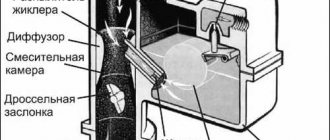
Diagram of the design and operation of the carburetor
I – first chamber; II – second chamber; 1 – accelerator pump drive lever; 2 – adjusting screw; 3 – starting device diaphragm; 4 – air channel of the starting device; 5 – electromagnetic shut-off valve; 6 – idle fuel jet; 7 – main air jet of the first chamber; 8 – idle air jet; 9 – air damper; 10 – sprayer of the main dosing system of the first chamber; 11 – accelerator pump nozzles; 12 – sprayer of the main dosing system of the second chamber; 13 – econostat sprayer; 14 – main air jet of the second chamber; 15 – air jet of the transition system of the second chamber; 16 – channel for balancing the float chamber; 17 – float chamber; 18 – needle valve; 19 – calibrated hole for fuel bypass into the tank; 20 – carburetor fuel filter; 21 – fuel supply fitting; 22 – power mode economizer diaphragm; 23 – fuel jet of the power mode economizer; 24 – ball valve of the power mode economizer; 25 – float; 26 – econostat fuel jet with tube; 27 – fuel nozzle of the transition system of the second chamber with a tube; 28 – emulsion tube of the second chamber; 29 – main fuel jet of the second chamber; 30 – outlet openings of the transition system of the second chamber; 31, 33 – throttle valves; 32 – slit of the transition system of the first chamber; 34 – outlet of the idle system; 35 – throttle valve zone heating unit; 36 – adjusting screw for the composition (the “quality” screw) of the idle mixture; 37 – engine crankcase ventilation fitting; 38 – fitting for supplying vacuum to the vacuum ignition regulator; 39 – main fuel jet of the first chamber; 40 – emulsion tube of the first chamber; 41 – ball valve of the accelerator pump; 42 – accelerator pump diaphragm.
A carburetor is used to prepare the fuel-air mixture of the required composition (depending on the engine mode). On engines -2108, -21081 and -21083, Solex-type carburetors are installed - emulsion type, two-chamber, with sequential opening of the throttle valves. The throttle valve drive is mechanical, cable. Carburetors have a balanced float chamber, a crankcase exhaust system, heating of the throttle valve area of the first chamber, a manual starting device, and an electromagnetic idle shut-off valve. The -21081 engine is equipped with a 21081-1107010 carburetor, the -2108 engine is equipped with a 2108-1107010 carburetor, and the -21083 engine is equipped with a 21083-1107010 carburetor. These carburetors are structurally similar and differ only in the flow sections of the jets.
Fuel is supplied to the carburetor through a strainer and needle valve. The latter maintains a given fuel level in the float chamber.
The float chamber is two-sectional (this design reduces the influence of fuel level fluctuations on engine operation when the vehicle turns and rolls). From the float chamber, fuel flows through the main fuel jets (first and second chambers) into the emulsion wells, where it is mixed with air passing through calibrated holes in the upper part of the emulsion tubes (main air jets). Through the nozzles, the fuel-air emulsion enters the small and large diffusers of the carburetor.
The idle system takes fuel from the emulsion well, after the main fuel jet of the first chamber. The fuel passes through the idle air jet (structurally combined with an electromagnetic idle shut-off valve), after which it is mixed with air from the channel from the idle air jet and from the expanding part of the diffuser (for stable operation when switching to idle mode). The resulting emulsion is fed under the throttle valve through a hole closed by a “quality” screw. The “quantity” screw (number of revolutions) adjusts the opening value of the throttle valve of the first chamber at idle.
When the throttle valve of the first chamber is partially opened (before the main metering system is turned on), the air-fuel mixture enters the chamber through a vertical slot located at the level of the throttle valve in the closed position; when the throttle valve of the second chamber is partially opened - through a hole located just above the throttle valve (second chamber) in the closed position.
The power mode economizer comes into operation when the throttle valves are opened significantly. Fuel is drawn from the float chamber through a ball valve. As long as the economizer diaphragm is held by vacuum in the intake manifold, the valve is closed. When the throttle valves open, the vacuum behind them drops and the valve begins to pass fuel, which flows through the economizer jet into the emulsion well, bypassing the main jet, enriching the mixture.
The econostat provides additional fuel supply directly from the float chamber (through the econostat nozzle and a tube system) into the second chamber. The econostat switches on at maximum power modes, further enriching the working mixture.
The accelerator pump is a diaphragm type, mechanically driven from the throttle valve axis of the first chamber through a profile cam. When the throttle valve opens, the cam acts on the lever, which in turn acts on the diaphragm. A portion of fuel is injected through nozzles into the carburetor chambers, enriching the combustible mixture during acceleration modes. The pump is equipped with two ball valves: a check valve is located in the channel connecting the float chamber with the cavity of the accelerator pump; it opens when it is filled with fuel (the gas pedal is released and the return spring moves the diaphragm back), and closes when fuel is pumped. The other valve is located in the sprayer; it opens under the pressure of the pumped fuel and closes under its own weight as soon as the fuel supply stops. This prevents fuel from leaking out of the channels and air leaks. The pump performance is not adjustable and depends only on the cam profile.
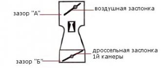
The starting device serves to enrich the air-fuel mixture when starting a cold engine. It is controlled from the driver’s seat with a “choke” handle via a rod. When the handle is pulled all the way, the three-arm air damper control lever, turning on an axis, acts with a profile groove on the air damper lever, closing it. In this case, with its outer profile (in the lower part) it acts on the throttle valve control lever of the first chamber, opening it slightly to the starting gap C (its value is adjusted by a screw on the lever). After the engine starts, the vacuum in the intake manifold increases; it is transferred to the cavity of the trigger device. Under the influence of vacuum, the diaphragm of the starting device, overcoming the resistance of the return spring, through the rod slightly opens the air damper to the starting gap B (its value is adjusted by a screw on the cover of the starting device). When the air damper control handle is recessed, gaps C and B are reduced; their value with a partially recessed handle depends on the profiles of the three-arm lever (its cutout and outer profile) and cannot be adjusted. If the choke control handle is pulled out, then when you press the gas pedal, only the throttle valve of the first chamber will open, while the throttle valve of the second chamber is blocked by the choke control lever. This prevents jerks and dips when driving with a cold engine (“on choke”).
Correct selection and replacement of the injection pump bypass valve
Reducing valves have an extremely simple design, but they are constantly subjected to high loads and quite often fail. Valve malfunction is manifested by deterioration of engine performance - it loses throttle response and in some modes there is a noticeable deterioration in its performance. In these cases, it is necessary to dismantle and check the valve, and, if it is faulty, replace it.
To replace, it is necessary to select a bypass valve of the same type and model that is installed on the injection pump by the manufacturer - only in this case there is a guarantee that the valve has the necessary characteristics and will ensure normal operation of the pump. Many valves allow adjustment of the pressure at which fuel is bypassed - this adjustment must be made in strict accordance with the instructions for maintenance and repair of the car/tractor. As a rule, adjustment comes down to changing the number of washers placed under the valve head, although there are exceptions - it all depends on the specific type of device.
With the correct selection, replacement and adjustment of the pressure reducing valve, the fuel pump will operate effectively in all modes, ensuring normal operating characteristics of the power unit.
The fuel line and the injector ramp that supplies the engine injectors operate under a pressure of about 3 bar. Since gasoline is supplied by an electric pump, the system uses a special valve that limits the fuel pressure. Otherwise, the nozzles will leak and the engine will choke on the over-enriched mixture. To avoid problems with fuel supply, you need to promptly diagnose the signs of a malfunction of the fuel pressure regulator (abbreviated as RTD) and know how to eliminate it.
Carburetor calibration data
| Options | 2108-1107010 | 21081-1107010 | 21083-1107010 | |||
| First camera | Second camera | First camera | Second camera | First camera | Second camera | |
| Mixing chamber diameter, mm | 32 | 32 | 32 | 32 | 32 | 32 |
| Diffuser diameter, mm | 21 | 23 | 21 | 23 | 21 | 23 |
| Main dosing system: | ||||||
| fuel jet marking | 97,5 | 97,5 | 95 | 97,5 | 95 | 97,5 |
| air jet marking | 165 | 125 | 165 | 135 | 155 | 125 |
| Emulsion tube type | 23 | ZC | 23 | ZC | 23 | ZC |
| Idle system and transition system | ||||||
| first chamber: fuel jet marking | 42* | — | 40* | — | 40* | — |
| air jet marking | 170 | — | 170 | — | 170 | — |
| Second chamber transition system: | ||||||
| fuel jet marking | — | 50 | — | 50 | — | 50 |
| air jet marking | — | 120 | — | 120 | — | 120 |
| Econostat: | ||||||
| conditional fuel jet flow rate | — | 60 | — | 70 | — | 70 |
| Power mode economizer: | ||||||
| fuel jet marking | 40 | — | 40 | — | 40 | — |
| spring compression force at a length of 9.5 mm, N | 1,5±10 % | — | 1,5±10 % | — | 1,5±10 % | — |
| Accelerator pump: | ||||||
| sprayer marking | 35 | 40 | 35 | 40 | 35 | 40 |
| fuel supply for 10 cycles (total for both chambers), cm3 | 11,5 | 11,5 | 11,5 | |||
| cam marking | 7 | — | 4 | — | 7 | — |
| Starting clearances: | ||||||
| air damper (gap B), mm | 3±0,2 | — | 2,7±0,2 | — | 2,5±0,2 | — |
| throttle valve (gap C), mm | 0,85 | — | 1,0 | — | 1,1 | — |
| Hole diameter for vacuum corrector, mm | 1,2 | — | 1,2 | — | 1,2 | — |
| Needle valve hole diameter, mm | 1,8 | 1,8 | 1,8 | |||
| Diameter of the fuel bypass hole into the tank, mm | 0,70 | 0,70 | 0,70 | |||
| Engine crankcase ventilation hole diameter, mm | 1,5 | — | 1,5 | — | 1,5 | — |
* Selected at the factory when setting up the carburetor.
Relative values of fuel jets for Solex carburetors
| Ratio | Diffuser diameters | |||||||||
| Economical | 14 | 95,0 | 102,0 | 107,0 | 115,0 | |||||
| Economical power | 13,5 | 98,5 | 105,8 | 111,0 | 119,3 | |||||
| Power moderate | 13 | 102,3 | 109,8 | 115,2 | 123,8 | |||||
| Power normal | 12,5 | 106,4 | 114,2 | 119,8 | 128,8 | |||||
| Powerful dynamic | 12 | 110,8 | 119 | 124,8 | 134,2 | |||||
| Sport | 11,5 | 115,7 | 124,2 | 130,3 | 140 | |||||
| Factory values | 14 | 95,0 | 102,0 | 107,0 | 115,0 | |||||
| Air quantity in diffuser | 1330 | 1428 | 1498 | 1610,0 | ||||||
Setting up the float chamber
This type of work allows you to adjust the optimal amount of gasoline in the float chamber. An incorrect level causes a decrease in power, uneven engine operation, and excessive fuel consumption.
- set of wrenches;
- thin probe (diameter 1 mm);
- pliers.
1. Remove the air filter and unscrew the carburetor cover.
2. Carefully remove the float chamber cover.
3. Check the condition and position of the floats. They should be parallel to the imprints of the side walls of the float bath on the gasket.
4. If they are displaced, we align them by bringing them together or spreading them apart.
5. Next, lay the lid horizontally with the floats up and use a feeler gauge to measure the distance from the bottom of the float to the gasket. It should be equal to 1 mm. If it is higher or lower, we continue further adjustment after installing the carburetor on the engine.
6. When fuel is pumped into the float chamber, its level should coincide with the red lines, as shown in the photo.
7. If the floats are set incorrectly, this level will be lower or higher. Simple adjustment is carried out by bending or bending the tongue of the floats, then closing the carburetor cover and pumping fuel.
For details on setting up the float chamber, see here
Tips for setting up, adjusting and troubleshooting
So, a dream has come true, a Solex carburetor is installed on the engine. Now the main thing is to tune it to the engine.
The first thing to do is set the level in the float chambers. This can be done as follows:
- Start the engine, let it run for 5 minutes, and gently apply gas. It should be noted that the Solex must start at some volume.
- After the engine is running, turn it off.
- Next, you need to carefully remove the fuel hose, as gasoline may spray out of it. This must be done so that when the carburetor cover is removed, gasoline does not pour into the chamber.
- Unscrew the 5 screws holding the carburetor cover and remove the choke cable.
- Lift the carburetor cover horizontally to avoid damaging the floats.
- Measure the distance from the surface of the gasoline in the chambers to the mating surface of the carburetor cap. It should be within 23-25 mm in two chambers, but the levels will differ from each other, so you can measure the level in each chamber and take the average. If the level is more or less than the specified level, then you need to carefully bend the tongue of the floats in the required direction, remove some of the gasoline from the chambers, and assemble everything in the reverse order.
- Start the car and look into the carburetor chambers with a flashlight for 30 seconds, during which time not a single drop of gasoline should fall. If the diffusers drip, this indicates an overflow;
- Next, measure the level in the chamber again; under normal conditions, the first stage will be completed.
Where to pour antifreeze. Read interesting and useful information about this process on our website.
Setting up the launcher
- open-end wrench 7;
- open-end wrench 8;
- flat screwdriver;
- electronic tachometer or multimeter with its function.
1. Remove the air filter from the carburetor. Pull the “suction” towards you as far as it will go. Next, you will need an assistant to start the engine. At this time, you are watching the starter flap, which should open slightly after starting.
2. If this does not happen, it means that the starter is not adjusted.
3. We begin the adjustment. Warm up the engine, turn it off and connect the tachometer as follows.
4. Pull out the choke and start the engine. The suction valve must be completely closed.
5. Next, use a screwdriver to press on the edge of the damper, opening it 30 0 .
8. In this position, holding the bolt with a screwdriver, tighten the locknut.
The adjustment process can be seen in this video
Idle setting
- flat screwdriver;
- electronic tachometer.
1. Start the engine, warm it up to operating temperature, and then turn it off. We press the “choke” all the way, opening the flap of the starter device as much as possible. We connect the tachometer using the same principle.
2. Start the engine, turn on all the lights and the heater fan at full power.
4. If in this way it was not possible to achieve the required speed, unscrew the quality screw to the maximum number of revolutions. Next, turn the quantity screw, setting the motor to 900 rpm. After this, use the quality screw to reduce the speed to 800 rpm.
Details in the video
Design and operating principle
The carburetor supplies the engine with a fuel-air mixture in various modes. When starting from a “cold” state, the throttle valve is manually fully opened (the so-called “choke”), and the mixture entering the cylinders is completely enriched. After the engine warms up, the speed drops and the choke can be removed. Drivers remove it in different ways, but it is recommended to do it gradually.
The fuel in the carburetor is transferred to the float chambers from the diaphragm pump, and the needle valve controls the gasoline level. Through the chamber, the fuel passes into the channels of the body, where it enters the nozzles, and through them it goes into the first chamber. A fuel-air mixture is formed, which is supplied directly to the cylinders by the gas pedal. The second camera turns on only during sharp acceleration and operation at high speeds.
At idle, the IACV (idle speed solenoid valve) is turned on, while the engine runs stably and the car consumes much less fuel. However, on some devices it can be disabled; if it breaks down, the speed and consumption will only increase slightly, but the car will drive.
Valve inspection and repair
Checking valves is a mandatory process when diagnosing a car. It will help to weed out some of the possible causes of the malfunction.
It often happens that the needle valve of the VAZ 2109 carburetor can sometimes simply “stick”. And this causes problems. If the fuel supply needle valve is faulty, it should be cleaned or replaced.
It happens that the valve stops working in very hot weather. This can be expressed in the fact that the car starts, but after ten to twenty seconds the engine stalls. Externally determining the cause can be very problematic.
Signs of a carburetor malfunction
It is a well-known fact: the quality of fuel in our country leaves much to be desired. As a result, the carburetor may become clogged with oils, solid particles, etc.
In this case, one or more signs may be observed:
- significantly increased fuel consumption;
- the engine does not start “cold”;
- loss of dynamics;
- "triple" of the engine.
You can restore functionality yourself. If unsuccessful, you can remove it and take it to a mechanic, who, with an experienced eye, will immediately identify the errors and adjust it “by eye,” after which the car will at least start.
First, you can try adjusting the carburetor without removing it from the car.
When adjustment is needed
Before you take a screwdriver and start turning the screws of the fuel unit, you need to understand one important point. It is as follows: adjusting the Solex carburetor is not a separate operation, but the final stage of the troubleshooting procedure or its scheduled cleaning. The only exception is if the settings were accidentally or unknowingly changed by you or someone else.
Solex carburetor - general view
The following signs indicate interruptions in the supply of the air-fuel mixture to the engine associated with Solex problems:
- the car began to stall at idle;
- fuel consumption has risen above normal and is accompanied by unstable operation of the power unit;
- a cold engine starts and immediately stalls, you have to make several attempts by manipulating the choke lever and the accelerator pedal;
- when you press the gas, a “failure” occurs, accelerating dynamics are completely absent;
- The car stalls while driving when you release the accelerator pedal while coasting.
Note. Unfortunately, the cause of the listed malfunctions is not always the carburetor. Problems with cold starts also arise when there is no compression in the cylinders, and the “culprits” for failures are often faulty spark plugs.
Wear of spark plugs also leads to increased gasoline consumption and the appearance of failures.
Point two: fixing not every problem ends with adjusting the fuel supply. The issue will be covered in more detail below, along with methods for repairing common breakdowns of the G8 carburetor. But in some cases you can’t do without adjustment:
- after removing or disassembling the Solex for the purpose of repair;
- upon successful cleaning or purging of the unit’s channels;
- after replacing rings or the entire piston group in a car engine;
- as a result of reconfiguring the timing in the ignition system, replacing high-voltage wires or installing new spark plugs.
Advice. Considering the low quality of fuel sold at many gas stations in Russia, it is recommended to remove the entire carburetor once every 20-25 thousand kilometers, disassemble it and thoroughly clean it with a compressor. After which you need to make adjustments.
Setup and adjustment
First of all, the engine warms up until the fan turns on. Next, adjust the speed by ear using the quantity screws. The operation should be smooth, with a sharp press on the gas pedal there should be no dips, and the speed should increase quickly and smoothly. The quality screw regulates the amount of exhaust gases. Ideally, no escaping gases should be visible from the exhaust pipe in the dry season (they will be, but not visible to the eye, if everything works correctly). Everything can also be done by looking at the tachometer readings. Unfortunately, many models of Soviet cars do not have it at all, so most often the adjustment will have to be done by ear.
Correct installation of the EM valve
It would seem, well, what’s so difficult, I screwed the valve into the carburetor and that’s it, but there are some nuances unknown to many, so if you do the installation yourself, without following them, you get new problems. So:
- It is extremely important to correctly screw the EMC onto the carburetor
- The most popular misconception is that it can only be tightened by hand.
- Moreover, this can be heard not only from a beginner, but also from middle-aged and very experienced specialists in reputable car services
- After such a recommendation, you and other drivers are in the deepest misconception
- The point here is that a valve that is loosely tightened (by hand) begins to dangle in the thread, and a poorly squeezed rubber band adds additional air leakage, which leads to a lean mixture - just one of the common reasons for unstable speed
- A similarly erroneous technique was proposed in an article titled “Capricious Valve” in a magazine titled “Behind the Wheel”:
- Let the engine idle, while turning off the power supply to the valve
- We tighten it little by little until the combustible mixture normalizes and the speed increases; if the engine stalls, this means that the valve is tightened
- Then start the engine and check the operation of the valve by disconnecting and connecting the power supply
- The whole point here is that the engine will stall as soon as the end of the nozzle has just begun to enter its seat, but it has not yet reached the end
- This “wisest” recommendation is also complemented by: “If necessary, you can tighten the EMC by about one more turn.”
- Doing this is just dangerous - if you squeeze the EMC, you can ruin the XX jet, or ruin the seat for the jet, which is even worse, and if you break the thread located in the carburetor cover, then the cost of repair will skyrocket
The results obtained in this way:
- The first case - just change the jet
- The second case is replacing the carburetor cap
- The third case is to replace or repair the cover (drill out and insert a threaded bushing)
- For your information, the Repair and Maintenance Manual tells us a tightening torque of 0.4 kilograms per meter (corresponding to 3.68 Newtons per meter)
- For a valve with a body diameter of 20 millimeters, the force required is 40 kilograms, and for a 13 millimeter valve - 61.5 kilograms
- You are unlikely to be able to create such a force with your fingers, but with a key about 15 centimeters long - 2.5 kilograms is normal
- In the book by the author Tyufyakov it is written like this: “The valve must be tightly wrapped in the lid, until the rubber sealing ring is completely pressed into the spacer tube.”
The most sensible recommendation on how to install an idle speed solenoid valve on a VAZ 2109 is as follows:
- It is necessary to remove its rubber seal from the EMC, then screw it in by hand until it stops, while counting the revolutions and also remember in which location you have the contact
- Then we put on the elastic band, and screw it first by hand, and then with the “13” key to its previous position (which we remembered), but no further
- I’ll add on my own that with the VAZ 2109 engine running, the idle speed solenoid valve can be slightly unscrewed (no more than 120 degrees) to achieve maximum speed
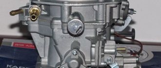
Lada 2106. › Logbook › Solex carburetor 083 (Pekar) a lot of literature. And Photos of works.
The figure shows a VAZ Solex 21083 carburetor.
The design of the carburetor VAZ Solex 21083.
1. Carburetor heating unit 2. Throttle valve of the first chamber 3. Pipe for suction of crankcase gases 4. Accelerator pump drive lever 5. Accelerator pump drive cam 6. Accelerator pump diaphragm 7. Power mode economizer fuel nozzle 8. Pump housing 9. Economizer diaphragm power modes 10. Shut-off solenoid valve 11. Idle fuel jet 12. Carburetor cover 13. Main air jet of the first chamber 14. Air damper 15. Accelerator pump nozzles with fuel supply valve 16. Starter diaphragm 17. Starter adjustment screw 18. Adjusting screw for the amount of idle mixture 19. Locking lever of the second chamber 20. Pipe for supplying vacuum to the vacuum regulator of the ignition distributor 21. Adjusting screw for the quality of the idle mixture 22. Throttle valve control sector 23. Throttle valve drive lever 24. Adjusting screw for opening the throttle damper of the first chamber 25. Air damper control lever 26. Starter rod 27. Electrical wire of the limit switch of the forced idle economizer 28. Air damper lever 29. Main air jet of the second chamber 30. Emulsion tube 31. Sprayer of the main dosing system of the second chamber 32. Fuel supply pipe 33. Fuel drain pipe into the tank 34. Fuel filter 35. Needle valve 36. Second chamber throttle valve 37. Second chamber throttle lever 38. Second chamber main fuel jet 39. Second chamber throttle drive lever 40. Float
Operating principle of RTD
The valve design and operating principle depend on the type of fuel system of a particular vehicle. There are 3 ways to supply gasoline from the tank to the injectors:
- The pump together with the regulator is installed inside the tank; fuel is supplied to the engine through one line.
- Gasoline is supplied through one tube and returned through another. The fuel system check valve is located on the distribution rail.
- The circuit without a mechanical regulator provides for electronic control of the fuel pump directly. The system contains a special sensor that registers pressure; the pump performance is regulated by the controller.
In the first case, the return flow is very short, since the valve and electric pump are interlocked into a single unit. The RTD, located immediately after the supercharger, dumps excess gasoline into the tank, and the required pressure is maintained throughout the supply line.
Reference. The first scheme with a regulator inside the gas tank has been implemented on all Russian-made VAZ cars.
The second option is used in most foreign cars. A valve built into the fuel rail allows excess fuel to flow into the return line leading to the tank. That is, 2 gasoline pipes are laid to the power unit.
There is no point in considering the third circuit - instead of a regulator, there is a sensor whose functionality is checked using a computer connected to the diagnostic connector.
A simple fuel pressure valve installed in the fuel pump unit consists of the following elements:
- cylindrical body with pipes for connecting the supply and return lines;
- a membrane connected to a locking rod;
- valve seat;
- spring.
Carburetor Colex 21083 and its design
This type of carburetor produces a lean mixture, and if you want to improve the dynamics of your car, we recommend installing jets with a larger cross-section. Below is a diagram of the Solex 21083 carburetor.
Take a closer look at what basic elements our device consists of.
Configuration Features
There are different versions of this carburetor, but 21083 is considered the basic version of the device with a minimum cross-section of diffusers. This carburetor is intended for installation on a 1.5-liter VAZ car engine. Solex 21083 is in great demand, since it is possible to make Solex of various modifications from this model.
According to official data, it is undesirable to install a Colex 21083 carburetor on power units with a displacement greater than 1.5 liters, since the engine will be “choked” at high speeds.
The following fact must be taken into account: the model in question is capable of supplying a lean mixture. And in order to obtain normal speed indicators on the UZAM motor, the jets will need to be replaced.
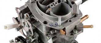
Solex 21083 carburetor design
1 – driving lever, second drive chamber; 2 – screw adjusting the amount of mixture supplied for idle speed; 3 – sector for heating the carburetor; 4 – engine crankcase ventilation pipe; 5 – drive lever for the accelerator pump; 6 – solenoid shut-off valve; 7 – air damper lever; 8 – carburetor cover; 9 – special screw for fastening the liquid chamber; 10 – liquid chamber body; 11 – carburetor body; 12 – throttle valve lever of the second chamber; 13 – control lever block directly for the throttle valves; A - special marks for precise installation of the bimetallic spring of the starting device.
1 – axis for the float; 2 – needle valve; 3 – float; 4 – special gasket for the carburetor cover; 5 – starter cover; 6 – screw; 7 – trigger device diaphragm; 8 – special gasket; 9 – air damper lever; 10 – idle fuel jet; 11 – solenoid shut-off valve; 12 – pipe for supplying a combustible mixture; 13 – carburetor cover; 14 – fuel filter; 15 – housing assembly with drive levers of a semi-automatic starting device; 16 – screws for adjusting the air damper of the starting gap and slightly opening the first throttle chamber; 17 – special clamp for securing the bimetallic spring housing; 18 – liquid chamber; 19 – assembled housing with a bimetallic spring; 20 – bimetallic spring screen.
Solex 21083 carburetor diagram
1 – screw adjusting the amount of feed mixture for idle speed; 2 – electric wire of the limit switch economizer for forced idling; 3 – carburetor heating unit; 4 – diaphragm for the accelerator pump; 5 – accelerator pump cover; 6 – drive lever of the accelerator pump; 7 – accelerator pump drive cam; 8 – economizer cover for power modes; 9 – diaphragm for economizer of power modes; 10 – fuel jet for power mode economizer; 11 – power mode economizer valve; 12 – nozzles with a fuel mixture supply valve for the accelerator pump; 13 – sprayers of the main dosing systems; 14 – air main jets with emulsion tubes; 15 – fuel main jets; 16 – carburetor body; 17 – adjusting screw for the throttle valve; 18 – stopper for the adjusting screw; 19 – stopper cap; 20 – throttle valve of the second chamber; 21 – throttle valve axis of the second chamber; 22 – throttle valve rod for opening the first chamber; 23 – block with throttle valve control lever; 24 – return spring of the throttle valve of the first chamber; 25 – driven lever, drive of the throttle valve of the second chamber; 26 – driving lever, driving the throttle valve of the second chamber; 27 – spring of the throttle valve drive levers of the second chamber; 28 – throttle valve of the first chamber; 29 – return spring of the throttle valve of the second chamber; 30 – plug for the screw adjusting (composition) the quality of the idle mixture; 31 – axis of the throttle valve of the first chamber; 32 – screw adjusting the quality of the supplied idle mixture
Let's consider the principle of operation
EPHH is used to disable the idle system in forced idling mode (abbreviated FHH), which occurs during engine braking, when the vehicle is moving downhill, or during gear shifting. So:
- By this, it prevents both the unproductive loss of gasoline and reduces atmospheric pollution, because under the conditions of the storage facility, the combustion of the working mixture is greatly deteriorated, and therefore the concentration of CH and CO in the exhaust gases increases sharply
- When the ignition is turned off, the supply of gasoline is also interrupted, which eliminates the diesel effect - spontaneous ignition of the combustible mixture in the cylinders
- Thanks to EPHH, fuel economy is 0.2-0.5 liters for every 100 kilometers driven
- The resulting diesel effect is dangerous, as it can lead to undesirable consequences, such as detonation (see VAZ 2109: engine detonation - how to remove it?) and knocking due to the resulting “reverse impacts” (this occurs with premature outbreaks inside the cylinders, when the piston has not yet completed the compression stroke), such impacts lead to damage to the piston rings, connecting rods and crankshaft
- Therefore, we do not recommend removing the EPHH (replacing the valve with a plug, or removing the shut-off needle from it), based not only on environmental considerations
- When you release the gas pedal, the gasoline supply is turned off at a crankshaft speed of more than 2100 rpm
- When the rotation speed decreases to approximately 1900 rpm, then the gasoline supply is resumed and the engine gradually returns to idle speed
- As you can see, the thresholds for triggering the feed when the speed increases or decreases are different (this is a normal phenomenon called “hysteresis”), this is what ensures the stability of the motor
- The working element of the EPHH is its electromagnetic valve (aka EM - valve, simply EMK), the valve has a shut-off needle, with which it shuts off the flow of gasoline through the carburetor jet
- Turning the EMC off and on is performed by the EPHH control unit (marked for VAZ - “5013”) and is located under the hood, screwed to the front wall above the battery - it looks like a black plastic box with a connector and a harness is connected to it
- It determines engine speed (and most importantly their thresholds of 1900 and 2100 rpm) based on a signal from the primary winding of the ignition coil
- And the limit switch informs him that the gas pedal is released (see the green wire with a chip that comes from the area of the right front corner of the carburetor)
What is a Solex 21083 carburetor?
Solex 21083 is one of the most popular domestic carburetors. It is mainly installed on 1.5-liter Russian and Soviet-made engines, although they can often be seen, for example, on old carburetor Japanese cars, since they are much simpler in design than their analogues. This carburetor will work normally only with a contactless ignition system, due to a number of technical features. There are many options for the Solex carburetor, however, 21083 is the basic option. It is this type that is most popular, as it can be easily modified by installing different jets, or even boring diffusers. It is not recommended to install Solex 21083 on cars with a displacement of more than 1.5 liters. The car, of course, will drive, but the failure in dynamics will be obvious; installing jets with greater cross-country ability will no longer help.
VAZ 2109: the solenoid valve does not work - how to fix it
Quite often, disturbances in the operation of the engine in the idle speed mode (idling speed) are associated with the appearance of a malfunction in the EPHH - the economizer of this idle speed. As a rule, for some reason, in a VAZ 2109 the solenoid valve in the carburetor stops working, and this causes problems. Anyone can diagnose and repair a malfunction; the valve is small and does not require disassembling the carburetor, so you can figure out something with the solenoid valve in a VAZ 2109 yourself.
Design and operating principle
The carburetor supplies the engine with a fuel-air mixture in various modes. When starting from a “cold” state, the throttle valve is manually fully opened (the so-called “choke”), and the mixture entering the cylinders is completely enriched. After the engine warms up, the speed drops and the choke can be removed. Drivers remove it in different ways, but it is recommended to do it gradually.
The fuel in the carburetor is transferred to the float chambers from the diaphragm pump, and the needle valve controls the gasoline level. Through the chamber, the fuel passes into the channels of the body, where it enters the nozzles, and through them it goes into the first chamber. A fuel-air mixture is formed, which is supplied directly to the cylinders by the gas pedal. The second camera turns on only during sharp acceleration and operation at high speeds.
At idle, the IACV (idle speed solenoid valve) is turned on, while the engine runs stably and the car consumes much less fuel. However, on some devices it can be disabled; if it breaks down, the speed and consumption will only increase slightly, but the car will drive.
What is a fuel injection pump bypass valve
The injection pump bypass valve (reducing valve) is a high-pressure fuel pump assembly of diesel engine power supply systems, an adjustable valve (hydraulic throttle) for draining excess fuel and maintaining the required fuel pressure in the pump.
The bypass valve performs several functions:
- Draining excess fuel from the pump;
- Removing air trapped in the fuel system;
- Maintaining constant fuel pressure inside the pump (in the channels of the pump sections of multi-section high-pressure fuel pumps and in the housing of the distribution high-pressure fuel pumps).
Signs of a carburetor malfunction
It is a well-known fact: the quality of fuel in our country leaves much to be desired. As a result, the carburetor may become clogged with oils, solid particles, etc.
In this case, one or more signs may be observed:
- significantly increased fuel consumption;
- the engine does not start “cold”;
- loss of dynamics;
- "triple" of the engine.
You can restore functionality yourself. If unsuccessful, you can remove it and take it to a mechanic, who, with an experienced eye, will immediately identify the errors and adjust it “by eye,” after which the car will at least start.
First, you can try adjusting the carburetor without removing it from the car.
Troubleshooting Tips
If the idle speed nozzle is clogged, you need to unscrew the solenoid valve together with the nozzle, rinse thoroughly, and clean the nozzle with the idle speed channel.
If the solenoid valve is faulty, it must be replaced. If the tightness of the connection between the top cover and the lower housing part is broken, the gasket must be replaced and coated with sealant.
A malfunction of the accelerator pump can be eliminated by cleaning and washing the nozzles and ball valves, replacing the diaphragm, spring, and cam. If the accelerator pump nozzles are incorrectly adjusted, the nozzles are replaced or adjusted so that the fuel jets are directed exactly into the hole that appears when the throttle valve is opened, without intersecting.
Depressurization in the system must be found and eliminated. If the main fuel and air jets become clogged, you need to rinse and clean them. Valve replacement is necessary if the idle air solenoid valve is not operating correctly.
If the fuel supply is adjusted incorrectly, it is worth adjusting the fuel supply using the quality and quantitative screws of the fuel mixture.
Possible malfunctions of the Solex carburetor may be indicated by: difficult starting of a cold or warm engine, as well as increased fuel consumption.
And if you do not want to take risks or do not understand the reasons for interruptions in the operation of the car, then contact the professionals.
Basic carburetor design
All carburetors in the Solex family have essentially the same design. The modifications differ in the parameters of the dosing elements, as well as some design features, which are described below. Emulsion-type carburetors, two-chamber, with sequential forced opening of the throttle valves, a balanced float chamber and heated coolant channels of the idle in the outlet area. Structurally, the carburetor consists of two main parts: the body and the cover.