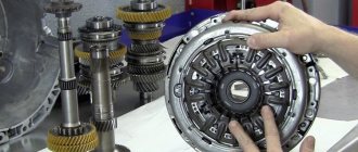
On cars of the tenth VAZ family, a five-speed manual gearbox is installed, which is combined with the main gear and differential. The gearbox housing of the tenth VAZ family consists of: a clutch housing, a rear housing cover 26 and a gearbox housing 30. During assembly, a sealant gasket is applied to these parts. A magnet is installed in the crankcase to retain wear products.
The input shaft 29 is made in the form of a block of drive gears that are in constant engagement with the driven gears of all five forward speeds. The secondary shaft 25 is hollow inside, this is done so that lubricant is supplied under the driven gears. It has a removable main gear gear 3. It also has driven gears 16, 18, 19, 21, 23 and synchronizers 17, 20, 24 for forward speeds. The front shaft bearings are 4 and 31 roller, the rear bearings 22, 28 are ball bearings. The clearance in the front bearings should not exceed 0.07 mm, and in the rear bearings - 0.04 mm. Under the front bearing of the secondary shaft 25 there is an oil sump 5, through which the flow of oil enters the shaft and then under all gear drives. The differential is two-satellite. The tension in its bearings is regulated by rings 13 by selecting their thickness. The driven gear 12 of the main gear is attached to the differential box flange 9.
VAZ 2110 gearbox diagram:
| 1 – clutch release bearing; | 18 – driven gear of the second gear of the secondary shaft; |
| 2 – guide sleeve of the clutch release bearing; | 19 – driven gear of the third gear of the secondary shaft; |
| 3 – main gear drive gear; | 20 – synchronizer for 3rd and 4th gears; |
| 4 – roller bearing of the secondary shaft; | 21 – driven gear of the fourth gear of the secondary shaft; |
| 5 – oil sump; | 22 – ball bearing of the secondary shaft; |
| 6 – satellite axis; | 23 – driven gear V of the secondary shaft transmission; |
| 7 – speedometer drive drive gear; | 24 – 5th gear synchronizer; |
| 8 – axle gear; | 25 – secondary shaft; |
| 9 – differential box; | 26 – rear cover of the gearbox housing; |
| 10 – satellite; | 27 – drive gear of 5th gear; |
| 11 – clutch housing; | 28 – ball bearing of the input shaft; |
| 12 – driven gear of the main gear; | 29 – input shaft; |
| 13 – adjusting ring; | 30 – gearbox housing; |
| 14 – tapered roller bearing of the differential; | 31 – roller bearing of the input shaft; |
| 15 – axle shaft seal; | 32 – input shaft oil seal; |
| 16 – driven gear of the 1st gear of the secondary shaft; | 33 – breather. |
| 17 – synchronizer of 1st and 2nd gears; |
The operating scheme is as follows: the input shaft (29) is made in the form of a block of drive gears, which are in constant engagement with the driven gears of all forward gears. The secondary shaft (25) is hollow, with a removable drive gear (3) of the main gear. On the secondary shaft there are driven gears (16, 18, 19, 21, 23) and synchronizers (17, 20, 24) for forward gears. The front bearings (4, 31) of the shafts are roller, the rear bearings (22, 28) are ball. An oil sump (5) is located under the front bearing of the secondary shaft, directing the flow of oil into the secondary shaft and further under the driven gears.
The differential is two-satellite. The preload in the differential bearings is adjusted by selecting the thickness of the ring (13). The driven gear (12) of the main gear is attached to the differential box flange.
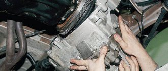
Repair work
If the adjustment does not give the desired result, you will have to work more carefully with the box. A common problem is knocking out the gears responsible for speeds 1 and 2.
When dismantling, make sure that each individual fastener is in good working order. The latches are springs, of which there are a total of three. The first one is the longest, it is responsible for speeds 1 and 2. The second is medium in size, and its prerogative is 3 and 4 speeds. The third detent is the smallest, and its “guardian” is fifth gear.
Gear shift drive diagram:
| 1 – gear selection rod lever; | 10 – hinge bushing; |
| 2 – gear selection lever; | 11 – hinge tip; |
| 3 – gearbox housing; | 12 – clamp; |
| 4 – clutch housing; | 13 – protective cover of traction; |
| 5 – gear selection rod; | 14 – gearbox control drive rod; |
| 6 – rod bushing; | 15 – gear shift lever; |
| 7 – rod seal; | 16 – ball joint cage; |
| 8 – protective cover; | 17 – ball joint of the gear shift lever; |
| 9 – hinge body; | 18 – jet thrust. |
The gearbox control drive consists of a gear shift lever (15), a ball joint (17), a rod (14), a gear selection rod (5) and gear selection and shift mechanisms (crumpled “P”).
To prevent spontaneous switching off of the P due to the axial movement of the power unit on its supports when the vehicle is moving, a reaction rod (18) is introduced into the gearbox control drive, one end of which is connected to the power unit, and a clip (16) of the ball joint of the lever (15) is attached to the other end ) switching P.
A lever (1) is attached to the inner end of the rod (5), which acts on the three-year lever (2) of the P selection mechanism. This mechanism is made as a separate unit and is attached to the plane of the clutch housing.
Product delivery options
Note! Below are the shipping methods available specifically for this product. Payment options may vary depending on the delivery method.
Detailed information can be found on the “Delivery and Payment” page.
Parcel by Russian Post
Available payment methods:
- Cash on delivery (payment upon receipt)
- Using cards Sberbank, VTB, Post Bank, Tinkoff
- Yandex money
- QIWI
- ROBOKASSA
Shipping throughout Russia. Delivery time is from 5 to 12 days.
Parcel by Russian Post 1st class
Available payment methods:
- Cash on delivery (payment upon receipt)
- Using cards Sberbank, VTB, Post Bank, Tinkoff
- Yandex money
- QIWI
- ROBOKASSA
Shipping throughout Russia. Delivery time is from 2 to 5 days. More expensive than regular delivery by Russian Post, approximately 50%. Parcel weight up to 2.5 kg
Express Parcel EMS
Available payment methods:
- Cash on delivery (payment upon receipt)
- Using cards Sberbank, VTB, Post Bank, Tinkoff
- Yandex money
- QIWI
- ROBOKASSA
Shipping throughout Russia. Delivery time is from 3 to 7 days. More expensive than regular delivery by Russian Post, approximately 100%.
Transport companies
Available payment methods:
- Using cards Sberbank, VTB, Post Bank, Tinkoff
- Yandex money
- QIWI
- ROBOKASSA
Delivery is possible to any locality where there is a representative office of the transport company. Delivery time is from 2 to 10 days. Sending large parcels is approximately 50% more profitable than by Russian Post.
Pickup from our warehouse
Available payment methods:
- Cash upon receipt
- Credit, installments
- Using cards Sberbank, VTB, Post Bank, Tinkoff
- Yandex money
- QIWI
- ROBOKASSA
Pickup times must coincide with store opening hours.
Gear selection mechanism:
| 1 – gear selection lever (forward); | 6 – reverse fork axis; |
| 2 – guide axis of locking brackets; | 7 – locking bracket; |
| 3 – axis of the gear selection lever; | 8 – reverse fork; |
| 4 – spring; | 9 – gear selection lever (reverse); |
| 5 – retaining ring; | 10 – housing of the gear selection mechanism. |
Two axles are mounted in the housing (10) of the gear selection mechanism. A three-year-old gear selector lever and two locking brackets (7 and 12) are installed on the axis (3). The other axis (2) passes through the holes of the locking brackets, securing them from turning. The gear selector lever arm (1) is used to engage P forward gear, the lever arm (9) is used to engage reverse gear, and the third arm is used by the gear selector rod lever. A fork (8) for engaging reverse gear is installed on the axle (6).
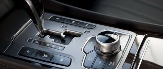
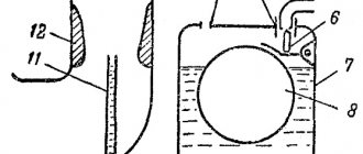
Oil is poured into the gearbox of a VAZ 2110, the level of which should be between the control marks of the oil level indicator.
Like any car, the VAZ 2110 also has a gear shift mechanism. The VAZ gearbox is five-speed, activated by a lever located in the car's interior.
In order to be able to fix problems yourself, you need to understand a little about how exactly the switching mechanism works, which is why there are cases when some speed does not turn on or goes out. And also know how to fix it on your own.
Design features
If you have a “ten” with an 8-valve engine, then the design provides two side and one rear support;
On a 16 valve engine there are two side mounts, one lower and one upper.
It is important to note that 8 valve engines on the 10 have a rear engine mount, while on the 16 valve there is none. But such motors can boast of having additional supports
Regardless of the design, the replacement procedure is performed using a similar method.
Malfunctions
In fact, it is quite easy to detect failed airbags, since engine vibrations will immediately increase.
If the power unit is working normally, but the body is shaking, vibration is felt on the steering rack, pedals, and dashboard, then there is no doubt that the engine mounts are worn out.
The vibration peak occurs when the engine starts and when it is turned off. If the rubber elements are completely worn out, then a knocking noise will begin to appear. It is caused by contact of engine elements with the supports.
To make sure the cushions are worn, turn on the engine, lift the hood, and visually inspect the supports and cushions. By placing your hand on the engine, you will tactilely feel an increase in vibrations compared to the normal behavior of the car.
There may be several reasons for problems.
| Causes | Peculiarities |
| Deformations | Deformation of elements can occur during the life of the pillows, under mechanical or temperature influences |
| Loss of elasticity | Rubber does not have a large margin of strength, so it ages over time. This effect increases when exposed to temperature changes. |
| Delamination and cracking | The pillow can literally fall apart and creep apart when exposed to chemically aggressive substances. |
Is replacement required?
If you find that the rear airbag or any other airbag has begun to wear out, you should under no circumstances delay repairs.
In addition to the discomfort of the driver and passengers when the car is moving, you risk delaying the breakdown until the moment when destructive processes begin in the operation of the gearbox and power unit.
When starting to repair engine mounts, you should think about whether it is worth changing the cushions separately, or replacing the mounts as a whole.
If the support is not damaged, it is not necessary to replace it. That is, in such situations it is enough to simply replace the pillow. A set of new pillows for a VAZ 2110 today costs about 1.3 thousand rubles. A set of supports will cost you 2.5 thousand rubles.
Doing the work yourself or contacting a service station is your choice. But you should know that you will be charged at least 300 rubles for replacing one pillow.
Checkpoint diagram
The gearbox design is as follows:
- To ensure gear shifting, the gearbox contains a primary shaft consisting of a gear block. They are constantly engaged with the drive gears from the first to the fifth speed (that is, those that are oriented towards driving forward);
- The secondary shaft is equipped with a drive gear for the main transmission, and it also has gear synchronizers that ensure forward movement of the driven gears. There are also bearings plus an oil sump;
- VAZ two-satellite differential, with the driven gear of the main gear attached to the flange of its box;
- the gearbox drive consists of a gear shift knob, a ball joint, a selector rod, a rod, gear selection mechanisms, and gear shifting mechanisms;
- Jet thrust is designed to protect the gearbox from flying out of gear. Its ends are attached to the support and the power unit.
Gear shift drive diagram
Repair work
If the adjustment does not give the desired result, you will have to work more carefully with the box. A common problem is knocking out the gears responsible for speeds 1 and 2.
When dismantling, make sure that each individual fastener is in good working order. The latches are springs, of which there are a total of three. The first one is the longest, it is responsible for speeds 1 and 2. The second is medium in size, and its prerogative is 3 and 4 speeds. The third detent is the smallest, and its “guardian” is fifth gear.
Adjustment
On a VAZ 2110, it is not so uncommon for the gears to shift poorly or get knocked out. A mechanism for adjusting the speed selection drive is provided specifically for this purpose.
Adjustment may be necessary if:
- the box was recently removed for repairs;
- one of the gears falls out;
- the speeds do not engage well or simply get knocked out when the car is moving.
If you have one of these problems, try making adjustments first. Its sequence:
- Under the bottom of the VAZ 2110, find and slightly loosen the nut on the bolt that tightens the clamp that secures the rod designed to control the gearbox;
- Use a screwdriver to slightly move apart the grooves in the end of the rod and the resulting gap on the clamp itself. This is necessary to ensure easy movement of the rod in relation to the gear selection rod. Place the rod in the neutral position;
- Release the shift knob from the cover in the cabin;
- Align the lever using a special template. This is done like this: install a template in the window of the rear speed lock bracket lining. After this, insert the lever axis stop into the groove of the template, pressing it without unnecessary force in the transverse direction;
- Then adjust the axial play of the rod in the rear direction, and its axial play by turning to the left;
- Install the clamp, not reaching a few millimeters from the end of the rod. Then tighten the clamp thoroughly with the bolt.
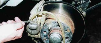
How to dismantle a car wheel
A tire puncture is a very common phenomenon and almost every car owner has encountered it. This malfunction does not cause problems if there is a tire service station nearby, where repairs will be carried out quickly and inexpensively. But it’s not always possible to seek services from such a service point, but you need a car and don’t have a spare tire or it’s already in use. In this case, you will have to do the repair yourself.
Restoring the integrity of the tire directly depends on its type. Tubeless products can continue to be used, but provided that the element that punctures it remains in the tire. Of course, there will be an air leak at the puncture site and the tire will have to be pumped up periodically, but you can drive. Additionally, the tubeless can be repaired using “first aid kits” for recovery. They allow you to carry out repairs even without removing the wheel from the car.
But it is impossible to repair tube wheels without disassembling them. To repair a puncture in the chamber, it must first be removed, and this is the main problem. Note that even with tubeless tires, the highest quality repairs can only be performed on the inside of the tire, and to do this it must be removed from the rim.
Nuances of the work
Disassembly would not be a problem if not for one feature. During the operation of the car, the tire at the point of contact with the rim is gradually “welded” to the metal. And this nuance causes the most problems during disassembly.
Video: do-it-yourself home tire fitting
At tire service stations, special presses are used to break the “weld,” so all the work looks very simple. In field or garage conditions, rubber tenaciously “holding” to the metal can cause a lot of trouble. But it is still possible to solve the problem.
So, the main task when disassembling a wheel is to separate its edge from the disk, along the entire circumference and on both sides. The rest of the disassembly process is not complicated and is very easy and quick, but safety precautions must be observed.
CPT diseases
VAZ 2110 owners often complain that the first gear is difficult to engage or crashes.
- often the synchronizer is to blame;
- perhaps the clamp spring has burst, the lever is hanging loose, the speeds are switched on as desired;
- The stem and fork may need replacement.
Another complaint is that second gear is difficult to engage and often gets knocked out.
Here you can suspect the main culprits:
- the second one flies out most often because the gear teeth do not mesh well with the clutch that turns on the speeds;
- The tips of the gear teeth and clutch are already worn out, so the speed is difficult to engage. If you don’t intervene, it will soon fly out;
- as an option, when it knocks out on bumps, the clutch dies.
Sometimes (albeit rarely) when the second one does not turn on well enough and falls out, replacing the retaining spring helps. If the speeds often drop out, some of them are difficult to turn on, which means that half-measures will no longer help - the box needs to be overhauled.
Whether you do it yourself, or go to a service center where they will repair it for you and also adjust the gear shift mechanism, decide for yourself, based on your own experience and skills.
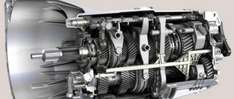
Cross-sectional design of a gearbox on a VAZ 2110
Main parts of the VAZ 2110 gearbox: 1 – rear cover of the gearbox housing, 2 – fifth gear drive gear, 3 – input shaft ball bearing, 4 – fourth gear drive gear of the input shaft, 5 – input shaft, 6 – third gear drive gear input shaft, 7 – gearbox housing, 8 – drive gear of the second gear of the primary shaft, 9 – reverse gear, 10 – intermediate reverse gear, 11 – drive gear of the first gear of the primary shaft, 12 – roller bearing of the input shaft, 13 – oil seal input shaft, 14 – breather, 15 – clutch release bearing, 16 – clutch release bearing clutch guide sleeve, 17 – main drive drive gear, 18 – secondary shaft roller bearing, 19 – oil sump, 20 – pinion axis, 21 – drive drive gear speedometer, 22 – axle gear, 23 – differential box, 24 – satellite, 25 – clutch housing, 26 – oil drain plug, 27 – main drive driven gear, 28 – adjusting ring, 29 – differential tapered roller bearing, 30 – oil seal axle shaft, 31 – driven gear of the first gear of the secondary shaft, 32 – synchronizer of the first and second gears, 33 – driven gear of the second gear of the secondary shaft, 34 – driven gear of the third gear of the secondary shaft, 35 – synchronizer of the third and fourth gears, 36 – driven gear of the fourth transmission of the secondary shaft, 37 – ball bearing of the secondary shaft, 38 – driven gear of the fifth gear of the secondary shaft, 39 – fifth gear synchronizer, 40 – secondary shaft.
Gearbox control drive VAZ 2110
VAZ 2110 backstage diagram: 1 – protective cover of the rod, 2 – gearbox control rod, 3 – gear shift lever, 4 – pin of the spherical gear shift lever, 5 – ball joint cage, 6 – ball joint of the gear shift lever, 7 – buffer , 8 – spring, 9 – reaction rod, 10 – gear selection rod lever, 11 – gear selection lever, 12 – gearbox housing, 13 – clutch housing, 14 – gear selection rod, 15 – rod bushing, 16 – rod seal, 17 – protective cover, 18 – hinge body, 19 – hinge bushing, 20 – hinge tip, 21 – clamp.
The principle of operation of the VAZ 2110 gearbox
The gearbox is mechanical, two-shaft, with five forward gears and one reverse gear, with synchronizers in all forward gears. It is structurally combined with the differential and main gear.
The gearbox housing consists of three parts (cast from aluminum alloy): the clutch housing, the VAZ 2110 gearbox housing and the rear cover of the gearbox housing. During assembly, a gasoline-oil-resistant gasket sealant (for example, KLT-75TM or TB-1215) is applied between them. There is a special magnet in the crankcase socket that retains metal wear products.
The input shaft of the VAZ 2110 is designed as a block of drive gears, which are in constant engagement with the driven gears of all forward gears. The secondary shaft of the VAZ 2110 is hollow (for supplying oil to the driven gears), with a removable drive gear of the main gear. It houses the driven gears and forward gear synchronizers. The front shaft bearings are roller, the rear are ball. The radial clearance in roller bearings should not exceed 0.07 mm, in ball bearings - 0.04 mm. An oil sump is located under the front bearing of the secondary shaft, directing the flow of oil into the shaft.
The differential is two-satellite. The preload in the bearings (0.25 mm) is adjusted by selecting the thickness of the ring installed in the gearbox housing housing under the outer ring of the differential bearing. The main drive driven gear is attached to the differential box flange.
The gearbox control drive consists of a gear shift lever, a ball joint, a rod, a gear selection rod and gear selection and shift mechanisms. TB-1324 thread glue is applied to the screws securing the rod and lever to the gear selector rod before assembly. The lever and hinge mounting screws vary in length, coating and tightening torques. The lever fastening screw is phosphated (dark color), 19.5 mm long, tightened with a torque of 3.4 kgf.m. The hinge fastening screw is cadmium-plated (golden), 24 mm long, tightened with a torque of 1.95 kgf.m. LSC-15 lubricant is placed in the ball joint before assembly.
To prevent the gears from spontaneously switching off due to the axial movement of the power unit when the vehicle is moving, a reaction rod is introduced into the gearbox control drive, one end of which is connected to the power unit, and a ball joint race for the gear shift lever is attached to the other end.
A lever is attached to the inner end of the rod, which acts on the three-arm lever of the gear selection mechanism. This mechanism is made as a separate unit and is attached to the plane of the clutch housing.
The housing of the gear selection mechanism of the VAZ 2110 has two axes. One has a three-arm gear selector lever and two locking brackets. The other axis passes through the holes of the locking brackets, securing them from turning. One arm of the gear selection lever is used to engage forward gears, the other is used to engage reverse gear, and the third arm is used by the gear selection rod lever. A reverse fork is installed on the axle.
The gearbox is filled with TM-5-9p oil at the factory, designed for 75,000 km. The oil level in the VAZ 2110 gearbox should be between the control marks on the oil level indicator.
“>
Transmission service
A guarantee of trouble-free operation of the gear shift unit is monitoring and timely replacement of lubricants. The plant fills with TM-5-9p oil, which needs to be changed every 60,000 km due to loss of viscosity. This simple procedure will take no more than half an hour if you have:
- 4 liters of GL-4 gear oil with viscosity 75W90;
- funnels;
- 17″ key.
The next steps are:
- Open the hood and remove the dipstick from the gearbox.
- Unscrew the drain plug.
- Drain the used oil into a container.
- Screw in the drain plug.
- Place a funnel in the dipstick hole.
- Fill with new oil.
- Insert the dipstick.
Causes of gearbox failure Causes of gearbox failure Before changing the oil, you need to warm it up by driving in normal mode for 15 minutes. The lubricant level is controlled by a dipstick - it should be between two marks. Experienced technicians advise replacing a new car after 3,000 km due to the appearance of metal particles in the oil after grinding in new parts.
Changing the oil
According to the documentation, the lubricant component in VAZ 2110 engines and transmissions must be changed every 15 thousand kilometers or at least once a year.
So, we need to warm up the engine well and prepare the required oil and, preferably, a new oil filter, as well as the tools necessary for the job.
gearbox housing 2110
To drain the waste, you will need to unscrew the plug from the oil pan. Next, within 10-15 minutes, the oil is drained into a special container, which will need to be prepared in advance. Then the drain plug returns to its original position and is screwed tightly. Now you can replace the old oil filter with a new one (if necessary).
Now that the old oil has been drained, pay attention to its color and presence of inclusions. If the oil is dark brown in color and to the touch contains various types of inclusions such as metal dust or pieces of dirt, then the transmission will need to be flushed.
For this purpose, special solutions are used, which are poured into the engine and gearbox before new oil. In this case, you will need to drive the car with such a solution for a short time and not quickly, five minutes along the garage will be enough, and then drain the mixture and the dirt that it has collected in the same way as described for the process of draining the “working off”.
In order to fill with fresh oil, you will need to remove the filler cap. In this case, from 3 to 4 liters of oil are poured into the engine, depending on the readings of the dipstick. Ideally, the oil level is between the min. marks. and max.
These marks are marked on the dipstick as the minimum and maximum values. Next, you will need to start the engine and wait until the oil light (or oil pressure light) goes out. After this, turn off the engine, check the oil level and, if necessary, remove excess or add more oil.
There are times when the light bulb just won't go off. In such cases, it is better to check the quality of the oil filter or replace it if it was not changed during the replacement process.